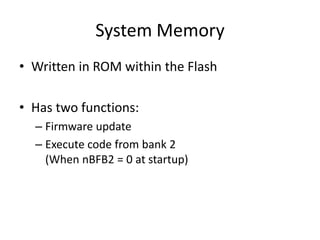
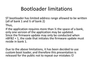
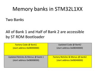
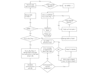
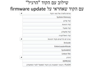
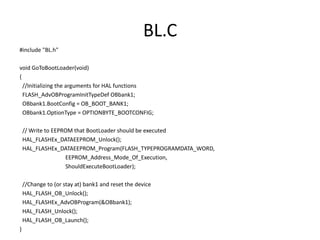
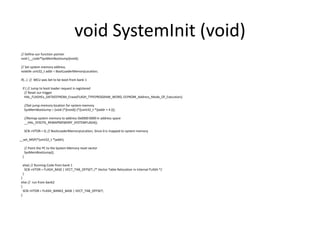
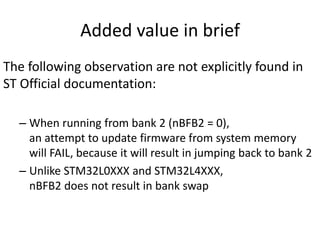
ST built-in Boot Loader
Applicable to STM32L1XX
Due to the technical limitations that will be detailed below,
Meprolight has decided not to use ST built in boot loader
Hence this presentation does not contain sensitive information
Agenda
• MCU Architerture 3 slides
• ST Built in Bootloader 3 slides
• Implementation Flowchart 1 slide
• Merging the code 3 slides
• External application 2 Slides
• Validation 1 Slide
© Hakim Weatherspoon, Computer Science, Cornell University
Basic Computer System
• A processor
is a device that executes instructions
Processor has some internal state in storage elements (registers)
• A memory
holds instructions and data
von Neumann architecture is assumed for simplicity
• A bus connects the two
regs
bus
processor memory
01010000
10010100
…
addr, data,
r/w
ARM Cortex-M Start up Sequence
• Electronically
– Fetch Stack Pointer from address 0x00
– Fetch Program Counter from address 0x04
• Software
– Execute assembly function Reset_Handler
(initialize vector table and call the followings)
– Execute c function SystemInit
Initializes clocks and VTOR
– Execute assembly function __iar_data_init3Initialize Initializes
variables
– Call function main
User program
But address 0x00 does not exist in Flash !
It is mapped to other address (0x08000000 in normal execution)
Where is the Vector Table located ?
System Memory
• Written in ROM within the Flash
• Has two functions:
– Firmware update
– Execute code from bank 2
(When nBFB2 = 0 at startup)
nBFB2 bit
• nBFB2 = 1 at startup  Normal Execution
• nBFB2 = 0 at startup
– Address 0x00 is mapped electronically
to System memory
– System memory Jumps to bank 2
• Undocumented important Takeaways:
– When running from bank 2 (nBFB2 = 0),
an attempt to update firmware from system memory
will FAIL, because it will result in jumping back to bank 2
– Unlike STM32L0XXX and STM32L4XXX,
nBFB2 does not result in bank swap
Bootloader limitations
ST bootloader has limited address range allowed to be written
(all of bank 1 and ½ of bank 2)
Thus,
If the application requires more than ½ the space of a bank,
only one version of the application may be updated.
Since the firmware update may only be conducted when
nBFB2 = 1, the code that initiates the firmware update must
reside in bank 1.
Due to the above limitations, it has been decided to use
custom boot loader, and therefore this presentation is
released for the public not to repeat our mistakes 
Memory banks in STM32L1XX
Two Banks
All of Bank 1 and Half of Bank 2 are accessible
by ST ROM Bootloader
Factory Code @ Bank1
(start address 0x08000000)
Updated Code @ Bank2
(start address 0x08040000)
Updated Reticles & Menus @ bank 1
(start address 0x08008000)
Factory Reticles & Menus @ bank2
(start address 0x08048000)
Wrtieto EEPROM:
Go_to_BL_Flag=1
Yes
Wake up
from Reset
Go_to_BL_Flag=0
Remap 0x00 to BLflash
Set stackpointer to BLStack
Jump to BL
Yes
Software
Reset
nBFB2 ==1 ?
Field Upgrade
Request ?
Normal code
Run from bank 2
No
Communication
with BL
Established ?
Establish
communication
with BL
Error message
(in application)
Reset (Opt. Byte)
No Writecodeto Bank2
And / Or Datato Bank1
Read To ValidateOK?
Set nBFB2 =0
(Initiatesreset)
Yes
No
Yes
Go_to_BL_Flag==1 ?
No
Remap 0x00
to Flash 2
Remap 0x00 to Flash1No
Set nBFB2 =1
Coderun from bank 1
Field Upgrade
Request ?
No
Yes
Yes
‫הקוד‬ ‫עם‬ ‫שילוב‬"‫הרגיל‬"
‫על‬ ‫שאחראי‬ ‫הקוד‬ ‫עם‬firmware update
BL.C
#include "BL.h"
void GoToBootLoader(void)
{
//Initializing the arguments for HAL functions
FLASH_AdvOBProgramInitTypeDef OBbank1;
OBbank1.BootConfig = OB_BOOT_BANK1;
OBbank1.OptionType = OPTIONBYTE_BOOTCONFIG;
// Write to EEPROM that BootLoader should be executed
HAL_FLASHEx_DATAEEPROM_Unlock();
HAL_FLASHEx_DATAEEPROM_Program(FLASH_TYPEPROGRAMDATA_WORD,
EEPROM_Address_Mode_Of_Execution,
ShouldExecuteBootLoader);
//Change to (or stay at) bank1 and reset the device
HAL_FLASH_OB_Unlock();
HAL_FLASHEx_AdvOBProgram(&OBbank1);
HAL_FLASH_Unlock();
HAL_FLASH_OB_Launch();
}
void SystemInit (void)
// Define our function pointer
void (__code*SysMemBootJump)(void);
// Set system memory address.
volatile uint32_t addr = BootLoaderMemoryLocation;
if(…) // MCU was Set to be boot from bank 1
if ( // Jump to boot loader request is registered
// Reset our trigger
HAL_FLASHEx_DATAEEPROM_Erase(FLASH_TYPEPROGRAM_WORD, EEPROM_Address_Mode_Of_Execution);
//Set jump memory location for system memory
SysMemBootJump = (void (*)(void)) (*((uint32_t *)(addr + 4 )));
//Remap system memory to address 0x0000 0000 in address space
__HAL_SYSCFG_REMAPMEMORY_SYSTEMFLASH();
SCB->VTOR = 0; // BootLoaderMemoryLocation; Since 0 is mapped to system memory
__set_MSP(*(uint32_t *)addr);
// Point the PC to the System Memory reset vector
SysMemBootJump();
}
else{ // Running Code from bank 1
SCB->VTOR = FLASH_BASE | VECT_TAB_OFFSET; /* Vector Table Relocation in Internal FLASH.*/
}
}
else // run from bank2
{
SCB->VTOR = FLASH_BANK2_BASE | VECT_TAB_OFFSET;
}
Requirement from external application
Input
The input to the external (smarthphone) is a binary file of size
X bytes,
where 0x38000 < X < 0x40000 changes from one update to
the other.
Goal
The binary file is to be copied into flash, where the first byte is
copied to address UpdateCodeStartAddress and the last
address is to be copied to UpdateCodeStartAddress + X, where
UpdateCodeStartAddress = 0x08008000.
After the file is copied (and verified that it is copied correctly),
the gun sight should be booted from bank 2 of the DM code.
The rest of the document is only a recommendation
Added value in brief
The following observation are not explicitly found in
ST Official documentation:
– When running from bank 2 (nBFB2 = 0),
an attempt to update firmware from system memory
will FAIL, because it will result in jumping back to bank 2
– Unlike STM32L0XXX and STM32L4XXX,
nBFB2 does not result in bank swap

ST Built in Boot loader

  • 1.
    ST built-in BootLoader Applicable to STM32L1XX Due to the technical limitations that will be detailed below, Meprolight has decided not to use ST built in boot loader Hence this presentation does not contain sensitive information
  • 2.
    Agenda • MCU Architerture3 slides • ST Built in Bootloader 3 slides • Implementation Flowchart 1 slide • Merging the code 3 slides • External application 2 Slides • Validation 1 Slide
  • 3.
    © Hakim Weatherspoon,Computer Science, Cornell University Basic Computer System • A processor is a device that executes instructions Processor has some internal state in storage elements (registers) • A memory holds instructions and data von Neumann architecture is assumed for simplicity • A bus connects the two regs bus processor memory 01010000 10010100 … addr, data, r/w
  • 4.
    ARM Cortex-M Startup Sequence • Electronically – Fetch Stack Pointer from address 0x00 – Fetch Program Counter from address 0x04 • Software – Execute assembly function Reset_Handler (initialize vector table and call the followings) – Execute c function SystemInit Initializes clocks and VTOR – Execute assembly function __iar_data_init3Initialize Initializes variables – Call function main User program But address 0x00 does not exist in Flash ! It is mapped to other address (0x08000000 in normal execution)
  • 5.
    Where is theVector Table located ?
  • 6.
    System Memory • Writtenin ROM within the Flash • Has two functions: – Firmware update – Execute code from bank 2 (When nBFB2 = 0 at startup)
  • 7.
    nBFB2 bit • nBFB2= 1 at startup  Normal Execution • nBFB2 = 0 at startup – Address 0x00 is mapped electronically to System memory – System memory Jumps to bank 2 • Undocumented important Takeaways: – When running from bank 2 (nBFB2 = 0), an attempt to update firmware from system memory will FAIL, because it will result in jumping back to bank 2 – Unlike STM32L0XXX and STM32L4XXX, nBFB2 does not result in bank swap
  • 8.
    Bootloader limitations ST bootloaderhas limited address range allowed to be written (all of bank 1 and ½ of bank 2) Thus, If the application requires more than ½ the space of a bank, only one version of the application may be updated. Since the firmware update may only be conducted when nBFB2 = 1, the code that initiates the firmware update must reside in bank 1. Due to the above limitations, it has been decided to use custom boot loader, and therefore this presentation is released for the public not to repeat our mistakes 
  • 9.
    Memory banks inSTM32L1XX Two Banks All of Bank 1 and Half of Bank 2 are accessible by ST ROM Bootloader Factory Code @ Bank1 (start address 0x08000000) Updated Code @ Bank2 (start address 0x08040000) Updated Reticles & Menus @ bank 1 (start address 0x08008000) Factory Reticles & Menus @ bank2 (start address 0x08048000)
  • 10.
    Wrtieto EEPROM: Go_to_BL_Flag=1 Yes Wake up fromReset Go_to_BL_Flag=0 Remap 0x00 to BLflash Set stackpointer to BLStack Jump to BL Yes Software Reset nBFB2 ==1 ? Field Upgrade Request ? Normal code Run from bank 2 No Communication with BL Established ? Establish communication with BL Error message (in application) Reset (Opt. Byte) No Writecodeto Bank2 And / Or Datato Bank1 Read To ValidateOK? Set nBFB2 =0 (Initiatesreset) Yes No Yes Go_to_BL_Flag==1 ? No Remap 0x00 to Flash 2 Remap 0x00 to Flash1No Set nBFB2 =1 Coderun from bank 1 Field Upgrade Request ? No Yes Yes
  • 11.
    ‫הקוד‬ ‫עם‬ ‫שילוב‬"‫הרגיל‬" ‫על‬‫שאחראי‬ ‫הקוד‬ ‫עם‬firmware update
  • 12.
    BL.C #include "BL.h" void GoToBootLoader(void) { //Initializingthe arguments for HAL functions FLASH_AdvOBProgramInitTypeDef OBbank1; OBbank1.BootConfig = OB_BOOT_BANK1; OBbank1.OptionType = OPTIONBYTE_BOOTCONFIG; // Write to EEPROM that BootLoader should be executed HAL_FLASHEx_DATAEEPROM_Unlock(); HAL_FLASHEx_DATAEEPROM_Program(FLASH_TYPEPROGRAMDATA_WORD, EEPROM_Address_Mode_Of_Execution, ShouldExecuteBootLoader); //Change to (or stay at) bank1 and reset the device HAL_FLASH_OB_Unlock(); HAL_FLASHEx_AdvOBProgram(&OBbank1); HAL_FLASH_Unlock(); HAL_FLASH_OB_Launch(); }
  • 13.
    void SystemInit (void) //Define our function pointer void (__code*SysMemBootJump)(void); // Set system memory address. volatile uint32_t addr = BootLoaderMemoryLocation; if(…) // MCU was Set to be boot from bank 1 if ( // Jump to boot loader request is registered // Reset our trigger HAL_FLASHEx_DATAEEPROM_Erase(FLASH_TYPEPROGRAM_WORD, EEPROM_Address_Mode_Of_Execution); //Set jump memory location for system memory SysMemBootJump = (void (*)(void)) (*((uint32_t *)(addr + 4 ))); //Remap system memory to address 0x0000 0000 in address space __HAL_SYSCFG_REMAPMEMORY_SYSTEMFLASH(); SCB->VTOR = 0; // BootLoaderMemoryLocation; Since 0 is mapped to system memory __set_MSP(*(uint32_t *)addr); // Point the PC to the System Memory reset vector SysMemBootJump(); } else{ // Running Code from bank 1 SCB->VTOR = FLASH_BASE | VECT_TAB_OFFSET; /* Vector Table Relocation in Internal FLASH.*/ } } else // run from bank2 { SCB->VTOR = FLASH_BANK2_BASE | VECT_TAB_OFFSET; }
  • 14.
    Requirement from externalapplication Input The input to the external (smarthphone) is a binary file of size X bytes, where 0x38000 < X < 0x40000 changes from one update to the other. Goal The binary file is to be copied into flash, where the first byte is copied to address UpdateCodeStartAddress and the last address is to be copied to UpdateCodeStartAddress + X, where UpdateCodeStartAddress = 0x08008000. After the file is copied (and verified that it is copied correctly), the gun sight should be booted from bank 2 of the DM code. The rest of the document is only a recommendation
  • 15.
    Added value inbrief The following observation are not explicitly found in ST Official documentation: – When running from bank 2 (nBFB2 = 0), an attempt to update firmware from system memory will FAIL, because it will result in jumping back to bank 2 – Unlike STM32L0XXX and STM32L4XXX, nBFB2 does not result in bank swap