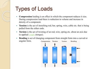
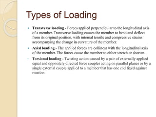
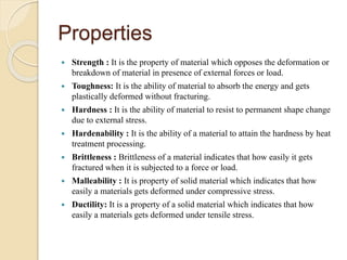
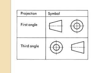
2. STRENGTH OF MATERIALS
o When an external force acts on the body & the body tends to
undergo some deformation.
o Due to cohesion between the molecules the body resists
deformation.
o The resistance by which the body opposes the deformation is known
as SOM.
o This resisting force per unit area is called stress or intensity of
stress.
3. STRESS & STRAIN
Stress:
o The force of resistance per unit
area offered by a body against
deformation is defined as Stress.
o External force acting on the body
is called load or force.
o Load is applied on the body
while the stress is induced in the
material of the body.
σ = P/A
σ - Stress,
P - External force / Load
A - Cross sectional Area.
◦ SI units – N/m^2
Strain:
o When body is subjected to some
external force, there is some
change in the dimension of the
body.
o The ratio of change of dimension
of the body to the original
dimension is known as strain.
o Strain is dimensionless
parameter.
4.
5. Types of Stress & Strain
Tensile stress:
Stress induced in the body when
subjected to two equal and
opposite pulls.
As a result there is increase in
length which is defined as tensile
stress.
Tensile stress acts normal to the
area and it pulls on the area.
σ = P/A
Tensile Strain:
When there is increase in length
of a body due to external force,
then the ratio of increased length
to the original length of body is
called Tensile strain.
℮ = dL / L
6. Types of Stress & Strain
Compressive Stress:
Stress induced in the body when
subjected to two equal and
opposite pushes.
As a result there is decrease in
length which is defined as
compressive stress.
Compressive stress acts normal
to the area and it pushes on the
area.
Compressive Strain:
When there is decrease in length
of a body due to external force,
then the ratio of decrease length
to the original length of body is
called compressive strain.
7.
8. Types of Stress & Strain
Shear Stress:
Stress induced in the body when
subjected to two equal and
opposite forces which are acting
tangentially across the resisting
section.
As a result body tends to shear
off across the section is known as
shear stress.
It is denoted by ‘τ’
Shear Strain:
When the body is subjected to
two equal and opposite forces
which are acting tangentially
across the resisting section.
The corresponding strain is called
as shear strain.
Volumetric Strain:
The ratio of change of volume of
the body to the original volume is
known as volumetric strain.
9. Strain Types
Linear Strain
Linear strain of a deformed body
is defined as the ratio of the
change in length of the body due
to the deformation to its original
length in the direction of the
force.
Lateral Strain
Lateral strain of a deformed body
is defined as the ratio of the
change in length (breadth of a
rectangular bar or diameter of a
circular bar) of the body due to
the deformation to its original
length (breadth of a rectangular
bar or diameter of a circular bar)
in the direction perpendicular to
the force.
10. Stress vs Strain Graph
Stress strain curve is a behaviour of material when it is subjected to load.
The relationship between the stress and strain that a particular material
displays is known as stress–strain curve.
It is unique for each material and is found by recording the amount of
deformation at distinct intervals of tensile or compressive loading.
.In this diagram stresses are plotted along the vertical axis and as a result of
these stresses, corresponding strains are plotted along the horizontal axis.
Stages of curve
A. Proportional Limit
B. Elastic Limit
C. Yield Point
D. Ultimate Stress Point
E. Breaking Point
11. STAGES OF CURVE
A. Proportional limit is point on the curve up to which the value of stress
and strain remains proportional.
B. Elastic limit is the limiting value of stress up to which the material is
perfectly elastic. Material will return back to its original position, If it is
unloaded before the crossing of point E.
C. Yield stress is defined as the stress after which material extension takes
place more quickly with no or little increase in load.
D. Ultimate stress point is the maximum strength that material have to bear
stress before breaking. It can also be defined as the ultimate stress
corresponding to the peak point on the stress strain graph.
E. Breaking point or breaking stress is point where strength of material
breaks. The stress associates with this point known as breaking strength
or rupture strength.
A. .
12.
13. Young’s Modulus
Ratio of tensile stress or
compressive stress to the
corresponding strain is a
constant.
It is denoted by ‘E’.
If you plot stress against strain
for an object showing (linear)
elastic behaviour, you get a
straight line.
This is because stress is
proportional to strain. The
gradient of the straight-line graph
is the Young's modulus.
14. Elastic constants
Poisson’s Ratio
The ratio of lateral strain to
longitudinal strain is a constant
for given material, when the
material is stressed within the
elastic limit.
µ = lateral strain / longitudinal
strain.
Hooke’s Law
Hooke’s law states that when a
material is loaded within elastic
limit, the stress is proportional to
strain produced by stress.
It means the ratio of stress to the
corresponding strain is a constant
within the elastic limit.
Factor of safety
It is defined as the ratio of
ultimate tensile stress to the
working stress.
15. Pressure & Force
Pressure:
Pressure is defined to be the
amount of force exerted per unit
area.
P=F/A
• P – Pressure,
• F – Normal Force ,
• A – Area of the surface in
contact.
• Units of pressure is Newton per
square meter. N/m^2
Force:
Force is an exertion of pressure
either focused toward or pulling
away from an object, and is
applied either by another object
or something such as gravity or
magnetism.
Force is the mass of the object
multiplied by its acceleration.
Units of force is Newton.
16.
17. Types of Beams
Cantilever Beam: A cantilever
beam is a beam which is fixed
from one end and free at the other
end.
Simply Supported Beam: A
beam which is supported or
resting on the supports at its both
the ends, is called simply
supported beam.
Overhanging Beam: In a beam,
if one of its ends is extended
beyond the support, it is known
as overhanging beam.
18. Types of Beams
Fixed Beams: A beam which has
both of its ends fixed or built in
walls is called fixed beam.
Continuous Beam: It is beam
which is provided with more than
two supports
19. Types of Loads
Compression loading is an effect in which the component reduces it size.
During compression load there is reduction in volume and increase in
density of a component.
Tension is the act of stretching rod, bar, spring, wire, cable etc. that is being
pulled from the either ends.
Torsion is the act of twisting of an rod, wire, spring etc. about an axis due
to applied couple (torque).
Bending is act of changing component from straight form into a curved or
angular form.
20. Types of Loading
Transverse loading - Forces applied perpendicular to the longitudinal axis
of a member. Transverse loading causes the member to bend and deflect
from its original position, with internal tensile and compressive strains
accompanying the change in curvature of the member.
Axial loading - The applied forces are collinear with the longitudinal axis
of the member. The forces cause the member to either stretch or shorten.
• Torsional loading - Twisting action caused by a pair of externally applied
equal and oppositely directed force couples acting on parallel planes or by a
single external couple applied to a member that has one end fixed against
rotation.
21. Types of Loads on beams
Point load is that load which acts
over a small distance. Because
of concentration over small
distance this load can may be
considered as acting on a point.
Point load is denoted by P and
symbol of point load is arrow
heading downward (↓).
Distributed load is that acts over
a considerable length or you can
say “over a length which is
measurable. Distributed load is
measured as per unit length.
TYPES OF DL
Uniformly Distributed load (UDL)
Uniformly distributed load is
that whose magnitude
remains uniform throughout
the length.
Uniformly Varying load
(Non-uniformly distributed load).
It is that load whose magnitude
varies along the loading length
with a constant rate.
22. Mechanical properties of a
material
The mechanical properties of a material are those which effect the
mechanical strength and ability of material to be moulded in suitable shape.
Some of the typical mechanical properties of a material are listed below-
Strength
1. Toughness
2. Hardness
3. Hardenability
4. Brittleness
5. Malleability
6. Ductility
7. Creep and Slip
8. Resilience
9. Fatigue
10. Elasticity
11. Plasticity
23. Properties
Strength : It is the property of material which opposes the deformation or
breakdown of material in presence of external forces or load.
Toughness: It is the ability of material to absorb the energy and gets
plastically deformed without fracturing.
Hardness : It is the ability of material to resist to permanent shape change
due to external stress.
Hardenability : It is the ability of a material to attain the hardness by heat
treatment processing.
Brittleness : Brittleness of a material indicates that how easily it gets
fractured when it is subjected to a force or load.
Malleability : It is property of solid material which indicates that how
easily a materials gets deformed under compressive stress.
Ductility: It is a property of a solid material which indicates that how
easily a materials gets deformed under tensile stress.
24. Properties
Creep and Slip : Creep is the property of material which indicates the
tendency of material to move slowly and deform permanently under the
influence of external mechanical stress.
Resilience :Resilience is the ability of material to absorb the energy when
it is deformed elastically by applying stress and release the energy when
stress is removed.
Fatigue: Fatigue is the weakening of material caused by the repeated
loading of material.
Elasticity: It is the property of material to regain its original shape after
deformation.
Plasticity: It is the property of a material which retains the deformation
produced under load permanently.
25.
26. Projections
Isometric Projection:
Isometric projection is a pictorial
representation of an object and it
is a single view, in which all the
three dimensions of an object are
revealed.
The three principal faces and
axes of an object are equally
inclined to the plane of
projection.
Orthographic Projection:
A projection is defined as a
representation of an object on a
2D plane.
The projections of an object
should convey all the three
dimensions, along with other
details of the object on a sheet of
paper.
27. Axonometric projection
An Axonometric projection of an object is one, in which all the three
faces of an object are inclined to plane of projection.
There are three main types of axonometric projection:
1. Isometric,
2. Dimetric, and
3. Trimetric projection.
28.
29. I & III Angle Projection
I Angle:
The object is imagined to be in I
quadrant.
The object lies between the
observer and plane of projection.
When views are drawn in their
relative position, top view comes
below front view, right side view
is drawn to the left side of
elevation.
III Angle:
The object is imagined to be in
III quadrant.
The plane of projection lies
between the observer and object.
When views are drawn in their
relative position, top view comes
above front view, right side view
drawn to the right side of
elevation.
30.
31. GD&T
GD&T stands for Geometric Dimensioning and Tolerancing.
Geometric dimensioning and tolerancing is an international language used
on drawings to accurately describe a part.
The language consists of a well-defined set of symbols, rules, definitions,
and conventions that can be used to describe the size, form, orientation, and
location tolerances of part features.
There are 14 types of symbols, and 5 types based on control types.
ASME Y14.5 – 2009 Version of Geometric Dimensioning & Tolerancing
(GD&T) Standard on Engineering Drawing
Benefits of incorporating G D & T
1. Elimination of errors, re-work, rejections and scrap
2. Fail safe approach to tolerancing
3. Easy to identify deviating processes that affect Quality and restore them
for maximizing yield
4. Improved Product Reliability