Download to read offline

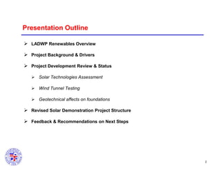
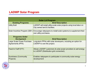
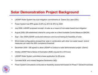
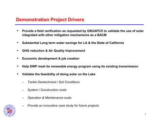
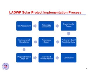
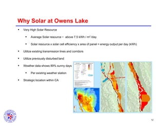

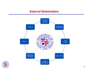
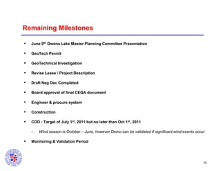

This document summarizes a presentation given by Yamen Nanne of the Los Angeles Department of Water and Power (LADWP) to the California State Lands Commission regarding a proposed solar demonstration project at Owens Lake. The presentation provides an overview of LADWP's renewable energy goals and programs, describes the drivers and development process for the proposed solar project, and summarizes the results of wind tunnel testing of different solar panel configurations to reduce dust emissions at Owens Lake as required. It requests feedback on next steps for the project, which includes further geotechnical analysis and stakeholder engagement before proceeding with the demonstration phase.


