Download to read offline


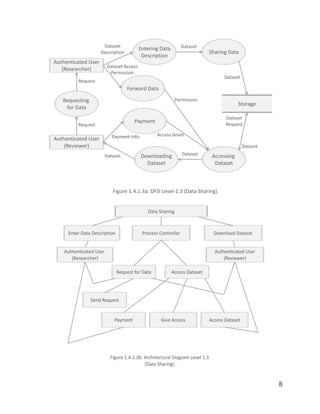
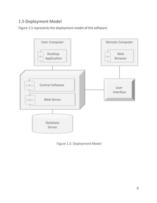

The document outlines the architectural design of the ResearchColab software, detailing the structures, components, and interactions necessary for its development. It includes context and data flow diagrams, archetypes of the principal components, and a deployment model. Additionally, it provides a mapping of architectural designs with respect to data flow diagrams at different levels.


