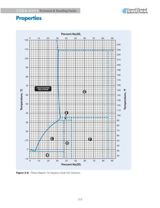
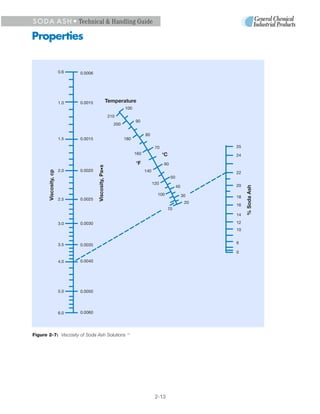
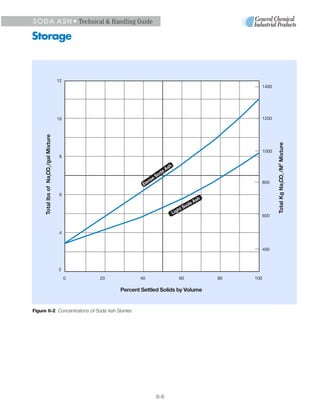
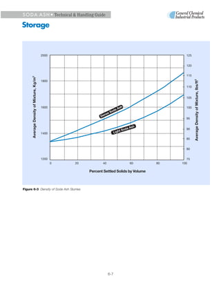
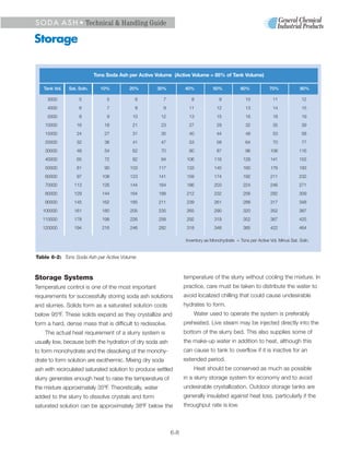
SODA ASH
S O D A A S H • Technical & Handling Guide


1 Introduction
        oda ash, the common name for sodium car-                 trona is heated in a kiln to drive off unwanted gases.


S       bonate (Na2CO3), has significant economic
        importance because of its applications in
manufacturing glass, chemicals, paper, detergents
                                                                 This transforms the ore to crude sodium carbonate.
                                                                 Water is added, and the solution is filtered to remove
                                                                 impurities. The liquid is then boiled off to form crystals,
and many other products. It has been used since                  which are separated in a centrifuge and dried.
ancient times. The Egyptians, for instance, umade                    Soda ash and materials made from it can be found
glass containers from soda ash as early as 3500 BC.              in most industries. It is such a basic material that gov-
And the early Romans expanded its use beyond glass               ernment and commerce agencies use soda ash pro-
as an ingredient in medicinals and bread.                        duction statistics to gauge the health of the economy.
                                                                 U.S. industry consumes soda ash in approximately the
                                                                 ratios shown in Figure 1-2 below:


                                                                                     Glass
                                                                                      40%               Export
                                                                                                          25%


                                                                                                     Chemical
                                                                                                       20%
                                                                 Misc 3%

                                                                 Water 3%
Figure 1-1: Green River Soda Ash Facility
                                                                 Pulp & Paper 3%                 Detergents 6%

    Much of the world’s supply of natural soda ash               Figure 1-2: US Soda Ash Markets Sectors

comes from trona ore. The largest known trona de-
posits are found in the Green River Basin, a prehistoric             General Chemical has been a soda ash producer
alkaline lakebed in southwest Wyoming known to geol-             for more than 100 years and uses the practical experi-
ogists as the Gosiute Lake. It is here, on 67 billion tons       ence gained during this time to support it customers in
of trona deposits, that General Chemical established its         shipping, storing and using soda ash. The following
Green River facility in 1968. This facility has been             document offers an overview of this knowledge base.
expanded over the years and now has a nameplate
capacity of 2.8 million tons.
    The Green River facility converts trona ore to soda
ash in a multi-step purification process. First, crushed


                                                           1-1
S O D A A S H • Technical & Handling Guide


2 Properties
           oda ash is a white, anhydrous, powdered or               of repose). Other physical and chemical properties are


S          granular material containing more than 99%
           sodium carbonate (Na2CO3) when shipped. The
accepted commercial standard for soda ash is
                                                                    common to all grades, whether in solid or liquid form.
                                                                    These are similar to those given for pure sodium car-
                                                                    bonate in standard reference books and other sources
expressed in terms of the equivalent sodium oxide                   from which much of the data that follow are derived,
(Na2O) content. A 99.5% soda ash is equivalent to
58.2% Na2O (the conversion equation is: % Na2CO3 x                     Temperature, °C            Density, kg/m 3

0.585 = % Na2O).                                                        851 (melting point)            1970
                                                                        900                            1940
    Soda ash is an alkali that has a high pH in concen-                1000                            1910
trated solutions. It can irritate the eyes, respiratory tract
and skin. It should not be ingested, because it can cor-            Table 2-2: Densities at Temperatures
                                                                    Above the Melting Point 2
rode the stomach lining.
    Soda ash is made in three main grades — light,                  e.g., the properties in Table 2-1 and the densities, dis-
intermediate and dense. These differ only in physical               sociation pressures and heats for formation, hydration
characteristics, such as bulk density and particle size             and solution in Tables 2-2 through 2-5.
and shape (which affects flow characteristics and angle
                                                                    Decomposition on Heating
                                                                    Anhydrous sodium carbonate loses weight when heat-
  Chemical formula               Na2CO3
  and name:                      Sodium carbonate,                  ed due to dissociation and volatilization according to
                                 anhydrous                          the following reaction:
  Molecular weight:              105.989                                Na2CO3 (solid) = Na2O (solid) + CO2 (gas).
  Absolute density:              2533 g/L @ 25°C                    Dissociation pressure rises with increasing temperature
                                 (See also Table 2-2)
                                                                    (Table 2-3).
  Melting point:                 851°C (1564°F)
  Decomposition on heating:      See Table 2-3
                                                                                                   Disassociation Pressure,
  Specific heat:                 1042 J/kg•K                           Temperature, °C             mm Hg
                                 (0.249 cal/g•°C or
                                 Btu/lb•°F)                            1000                              1.5   ±0.5
                                                                       1100                              5.5   ±1.0
  Heat of fusion:                315,892 J/kg(1)
                                                                       1200                             14.0   ±0.5
                                 (75.5 cal/g or 136 Btu/lb)
                                                                       1300                             20.0   ±1.0
  Heat of formation from                                               1400                             66.0
  the elements:                  10.67 x 10⁶ J/kg
                                 (2550 cal/g or 4590
                                                                    Table 2-3: Disassociation Pressures of Soda Ash   3

  Btu/lb
  Heat of hydration:             See Table 2-4
                                                                    Hydrates of Sodium Carbonate
  Heat of solution:              See Table 2-5
                                                                    Sodium carbonate has three hydrate forms: Sodium car-
  Stability in air:              Slowly absorbs moisture
                                 and carbon dioxide to form         bonate monohydrate, heptahydrate and decahydrate.
                                 sodium sesquicarbonate                 Sodium carbonate monohydrate (Na2CO3•H2O)
                                 (Na2CO3•NaHCO3•2H2O)
                                                                    contains 85.48% Na2CO3 and 14.52% water of crystal-
  Bulk density:                  See Table 2-12
                                                                    lization. It separates as small crystals from saturated

Table 2-1: Properties of Soda Ash


                                                              2-1
S O D A A S H • Technical & Handling Guide

Properties

aqueous solutions above 35.4°C (95.7°F). It can be
                                                                                                Monohydrate     Heptahydrate          Decahydrate
formed by wetting soda ash with a calculated quantity                                           Na2CO3•H2O      Na2CO3•7H2O          Na2CO3•10H2O
of water at or above this temperature. It loses water on
                                                                     Heat of formation
heating, and its solubility decreases slightly with                  from the elements,
                                                                     J/kg                       11.531 x 10⁶     13.790 x 10⁶         14.263 x 10⁶
increasing temperature. It converts to Na2CO3 upon
contact with its saturated solution at 109°C (228°F).
                                                                     cal /g
                                                                     Btu / lb
                                                                              }  hydrate        2756
                                                                                                4960
                                                                                                                 3296
                                                                                                                 5932
                                                                                                                                      3409
                                                                                                                                      6138

    Sodium carbonate heptahydrate (Na2CO3 •7H2O)                     Heat of hydration,
                                                                                                125.5x 10³       654.4 x 10³          873.6x10³
                                                                     J/kg
contains 45.7% Na2CO3 and 54.3% water of crystal-
lization. It is of no commercial interest because its sta-
                                                                     cal /g
                                                                     Btu / lb
                                                                              }Na2CO3           30.0
                                                                                                54.0
                                                                                                                 t 56.4
                                                                                                                 281.5
                                                                                                                                      208.8
                                                                                                                                      375.8

bility range only extends from 32.0° to 35.4°C (89.6° to           Table 2-4: Heat of Formation and Hydration at 25°C 4
95.7°F).
    Sodium carbonate decahydrate (Na2CO3 •10H2O),                                    Solute                             Heat Quantity
commonly called “sal soda” or “washing soda,” usually                                                  %        J/kg (4)       cal/g       Btu/lb
                                                                    Formula                grams     Na2CO3     Na2CO3         Na2CO3      Na2CO3
forms large, transparent crystals containing 37.06%
                                                                    Na2CO3                 105.989    2.86     231.8 x 10³       55.4        99.7
Na2CO3 and 62.94% water of crystallization. It can be
                                                                    Na2CO3 •H2O            124.004    2.84     106.2 x 10³       25.4        45.6
crystallized from saturated aqueous solutions between
                                                                    Na2CO3 •7H2O           237.094    2.76     -422.6 x 10 3
                                                                                                                                -101.0     -181.9*
-2.1 and 32.0°C (28.2 and 89.6°F) or by wetting soda                Na2CO3•10H2O           286.139    2.73     -641.8 x 10³     -153.4*    -276.1
ash with a calculated quantity of water in this tempera-
ture range. The crystals readily effloresce in dry air,            Table 2-5: Heat of Solution at 25°C
                                                                   (One Mole of Sodium Carbonate Dissolved in 200 Moles H2O)
forming a residue of lower hydrates (principally the
monohydrate form).
                                                                   50% slurry, about 42% of the soda ash dissolves to

Heat of Solution                                                   form a saturated 32% solution. The remaining 58%

Heat is released when anhydrous or monohydrate sodi-               soda ash forms monohydrate crystals. The total heat

um carbonate dissolve in water. Heat is absorbed when              developed in preparing a 50% slurry is:

the heptahydrate or decahydrate forms dissolve in                  (0.42 x 134) + (0.58 x 54) = 88 Btu/lb. of soda ash.
water. The stronger the concentration, the greater the
                                                                       When more water is added to the slurry, monohy-
heat released or absorbed per unit of Na2CO3 dis-
                                                                   drate dissolves to saturate the water. For example,
solved. Use Fig. 2-1 to calculate the heat absorbed
                                                                   when one gallon of water is added to soda ash slurry,
when diluting a sodium carbonate solution. For exam-
                                                                   about 4 pounds of soda ash will dissolve (4.7 lbs. of
ple, when a 25% solution is diluted to 10%, tempera-
                                                                   monohydrate). Subtracting the heat of formation from
ture decreases through the absorption of:
                                                                   the heat of solution gives the net heat released by dis-
    131.7 – 114.3 = 17.5 Btu/lb. Na2CO3.                           solving a saturated monohydrate slurry with 1 gallon of

When soda ash is dissolved in water to form a 32%                  water:

saturated solution, 135 Btu/lb. of heat is released                    4 x (134 – 54) = 282 Btu of heat.

(Fig. 2-1). As additional soda ash is added to the satu-
rated solution, monohydrate crystals are formed. This
heat of formation is 54 Btu/lb (Table 2-4). If equal
weights of soda ash and water are mixed, forming a

                                                             2-2
S O D A A S H • Technical & Handling Guide

Properties


                                             Percent Na CO   2       3


                            0   5    10        15        20              25   30      35
                      140
                                                                                           320


                      135


                      130
                                                                                           300


                      125


                                                                                            280
                      120
              3
       Btu/lb Na CO


                                                                                                  J/kg x 103
                      115
              2


                                                                                           260

                      110


                      105
                                                                                           240


                      100


                      95                                                                   220


                      90


                                                                                           200
                      85
                            0   5    10        15        20              25   30       35

                                            Percent Na CO2       3


Figure 2-1: Heat Evolved in Dissolving Soda Ash to Form Solutions of Varying Concentrations @ 25°C 3


                                                             2-3
S O D A A S H • Technical & Handling Guide

Properties

Solubility                                                         The region below and to the right of the curve contains
Sodium carbonate, although readily soluble in water, is            either undissolved solids in contact with saturated solu-
unusual in that it reaches maximum solubility at the rela-         tions or solids alone (Table 2-6).
tively low temperature of 35.4°C (95.7°F). At this point,               This diagram helps trace the effects of cooling,
100 parts of water dissolves 49.7 parts of Na2CO3 to               heating and changing concentrations. For example, a
yield a 33.2% solution by weight. Solubility decreases             20% Na2CO3 solution is unsaturated at all temperatures
above this temperature, so there are two saturation tem-           above 22.4°C (72.3°F), which is where the 20% con-
peratures for concentrations between about 29% and                 centration line crosses the saturation curve. Below this
33.2%. The phase diagram (Fig. 2-2) portrays this rela-            temperature, the solid phase (Na2CO3 •10H2O) begins
tionship by tracing solubility (as % Na2CO3) between               to form, increasing in amount as temperature falls. This
-2.1 and 109°C (28.2 and 228.2°F).                                 phase change causes the concentration of the saturat-
    Solubility data above about 105°C represent solu-              ed solution in contact with the crystals to decrease,
tions held above atmospheric in order to prevent boiling,          until at -2.1°C (28.2°F), the liquid phase disappears
since the boiling point-concentration curve crosses the            leaving only a mixture of solid Na2CO3 •10H2O and ice.
solubility curve at about 105°C. Unsaturated solutions
exist in the area above and to the left of this curve.


                                                                                           Liquid Phase
                Percent           Temperature,                                           Percent Soda Ash        Transition
     Area      Soda Ash               °C                          Solid Phases              in Solution            Points

                              At and                                                                           Percent
             from     to      Below    from       to                                       from         to    Soda Ash    °C

       A      0        5.8              0        -2.1                 ICE                  0            5.8

       B      0       37.0      -2.1                         ICE + Na2CO3•10H2O                  None           5.8       -2.1

       C      5.8     37.0             -2.1      32.0          Na2CO3•10H2O                5.8      31.2

       D     37.0     45.7     32.0                      Na2CO3•10H2O + Na2CO3•7H2O              None          31.2       32.0

       E     31.2     45.7             32.0      35.4             Na2CO3•7H2O             31.2      33.2

       F     45.7     85.5     35.4                       NaCO3•7H2O + Na2CO3•H2O                None          33.2       35.4

       G     30.8     85.5             35.4    109.0              Na2CO3•H2O              33.2      30.8

       H     85.5    100.0    109.0                         Na2CO3•H2O + Na2CO3                  None          30.8      109.0

       I     30.8    100.0                  109 and                 Na2CO3                30.8
                                             above


Table 2-6: Phase Diagram Defined (see Figure 2-2)


                                                            2-4
S O D A A S H • Technical & Handling Guide

Properties

                                              Percent Na CO
                                                        2     3


                           0   10   20   30     40    50          60   70   80   90
                     120

                                                                                      240

                     110                                                              230

                                                                                      220
                     100
                                                                                      210

                                                                                      200
                      90
                                                                                      190

                                                                                      180
                      80
                                                                                      170

                      70                                                              160


                                                                                            Temperature, oF
   Temperature, oC


                                                                                      150

                      60                                                              140

                                                                                      130
                      50
                                                                                      120

                                                                                      110
                      40
                                                                                      100

                                                                                      90
                      30
                                                                                      80

                      20                                                              70

                                                                                      60

                     +10                                                              50

                                                                                      40
                       0
                                                                                      30

                                                                                      20
                     -10
                           0   10   20   30     40    50          60   70   80   90
                                              Percent Na CO
                                                        2     3


Figure 2-2: Phase Diagram for Aqueous Soda Ash Solutions


                                                            2-5
S O D A A S H • Technical & Handling Guide

Properties

The composition of such a solidified mass may be                     If the mixture is cooled below 32°C, it solidifies to a
calculated from:                                                 mixed solid, which contains Na2CO3 • 7H2O (45.7%
                                                                 Na2CO3) and Na2CO3 • 10H2O (37.0% Na2CO3) in the
     (A – C) x 100 = W                                           proportion of:
     (B – C)
                                                                      (40 – 37.0) x 100 = 34.5% Na CO • 7H O
                                                                                                  2  3    2
where: A = % Na2CO3 in the original mixture.                          (45.7-37.0)
         B = % Na2CO3 in the richer component of
             the mixture at the final temperature.               and 65.5% Na2CO3 • 10H2O.
                                                                     The solubility of soda ash in the presence of appre-
         C = % Na2CO3 in the leaner component of
                                                                 ciable amounts of foreign salts, such as sodium chlo-
             the mixture at the final temperature.
                                                                 ride, sodium sulfate and sodium nitrate, changes how
         W = weight % of the richer component in final
                                                                 well the phase diagram in Fig. 2-2 applies. See the
             mixture.
                                                                 International Critical Tables or the Solubilities of
                                                                 Inorganic and Metal Organic Compounds by A Seidell,
    In the above example, where a 20% Na2CO3 solu-
tion is cooled below -2.1°C so it solidifies, the richer         4th Edition, 1958 (Vol. 1) and 1965 (Vol. 11) for the

component of the final mixture (Na2CO3 • 10H2O) has              effects of salts on the solubility of sodium carbonate.

37.0% Na2CO3 and the leaner component (ice) has 0%               Solution Specific Gravity and Density
Na2CO3. The final mixture then contains:                         Soda ash has a solubility limit of 14.5% Na2CO3 at
                                                                 15.6°C (60°F). Table 2-7 lists densities at 15.6°C and
     (20 – 0) x 100 = 54.1% Na CO • 10H O
                              2  3     2                         specific gravities for concentrations of sodium carbonate
     (37 – 0)
                                                                 up to 14.0% (from the International Critical Tables 5).
and the rest is solid ice.
                                                                     Higher concentrations are possible above 15.6°C.
    Referring to the phase diagram (Fig. 2-2), a mixture
                                                                 The specific gravities of saturated solutions above
of 40% Na2CO3 and water at 50°C contains Na2CO3 •
                                                                 15.6°C lie on a smooth curve (Fig. 2-3) 6. Table 2-8 lists
H2O crystals (85.5% Na2CO3) in equilibrium with its sat-
                                                                 values at saturation for concentrations of 15% and
urated solution (32% Na2CO3). The physical composi-
                                                                 above. Crystallization occurs when temperature falls
tion of the mixture is:
                                                                 below that shown for these solutions.
     (40 – 32) x 100 = 15% Na CO • H O                               The specific gravity of sodium carbonate solutions
                             2  3   2
    (85.5 – 32)                                                  decreases with increasing temperature. Concentration
and 85% is saturated solution.                                   can be determined if solution specific gravity and tem-
    Cooling this mixture to 35°C changes the solid               perature are known (Table 2-8 and Fig. 2-4).
phase from Na2CO3 • H2O to solid Na2CO3 • 7H2O
containing 45.7% Na2CO3 in contact its saturated solu-
tion (33% Na2CO3). The mixture now consists of:

     (40 – 33) x 100 = 55% Na CO • 7H O
                             2  3    2
    (45.7 – 33)

and 45% is saturated solution.


                                                           2-6
S O D A A S H • Technical & Handling Guide

Properties


                    35


                    30                                                                                                                   re
                                                                                                                                       tu                                   o   F)
                                                                                                                                     ra                                  0
                                                                                                                                   pe                           0
                                                                                                                                                                   o   /6
                                                                                                                                  m                           (6
                                                                                                                                Te                    o   C
                                                                                                                           n
                                                                                                                        tio                       5  .6
                                                                                                                      ra                    o   /1
                                                                                                                    tu                      6
                    25                                                                                            Sa                    15.
                                                                                                              @                    to
                                                                                                                              ed
                                                                                                                           ct
                                                                                                                         re
                                                                                                                    C or
            3
    Percent Na CO


                    20
            2


                    15


                                                                         o    F)
                                                                          0
                                                                   o   /6
                                                                0
                    10                                        (6
                                                      o   C
                                                    6
                                                 5.
                                           o   /1
                                        .6
                                      15
                                  @

                    5


                    0
                         1.0   1.05                           1.10                 1.15         1.20         1.25                   1.30                                1.35         1.40


                                                                                          Specific Gravity


Figure 2-3: Specific Gravity of Soda Ash Solutions


                                                                                          2-7
S O D A A S H • Technical & Handling Guide

Properties


                                                  Density–Degrees Baumé @ 60 oF
                                0     5      10      15       20      25         30          35          40
                     110                                                                                         230

                                                                                                                 220

                     100                                                                                         210

                                                                                                                 200
                      90
                                                                                                                 190

                                                                                                                 180
                      80
                                                                                                                 170

                      70                                                                                         160
                                                                                      30%
                                                                                                                 150
                                                                   20%
                      60                                                                                         140
   Temperature, oC


                                              10%


                                                                                                                       Temperature, oF
                                                                                                                 130
                      50
                               0%                                                                                120

                                                                                                                 110
                      40
                                                                                                                 100

                                                                                                                 90
                      30
                                                                                                                 80

                      20                                                                                         70

                                                                                                                 60

                     +10                                                                                         50

                                                                                                                 40
                       0                                                                                         30

                                                                                                                 20
                     -10
                        0.95   1.00   1.05        1.10      1.15    1.20       1.25   1.30        1.35    1.40


                                                          Density (kg/m3)

Figure 2-4: Concentration of Sodium Carbonate Solutions at Varying Densities and Temperatures


                                                                         2-8
S O D A A S H • Technical & Handling Guide

Properties

Specific Heat
                                                                                                     Kilograms
Figure 2-5 shows the specific heat of sodium car-                         Percent                     Sodium                                   Pounds
                                                             Percent     Equivalent     Specific     Carbonate        Degrees    Weight of     Sodium
bonate solutions at 20°C 7 and at 30 and 76.6°C 8.           Sodium       Sodium         Gravity     per Cubic        Baumé      One Gallon   Carbonate
                                                            Carbonate      Oxide           at         Meter at        at 60o F     at 60o F   per Gallon
For example, the heat required to raise the tempera-        (Na2CO3)      (NA2O)      15.6o/15.6oC    15.6oC         (Am.Std.)    (Pounds)     at 60o F
ture of 1000 gallons of 10% Na2CO3 solution from
                                                                   1        0.6         1.010         10.1             1.4          8.42         0.08
68°F to 170°F is                                                   2        1.2         1.021         20.4             3.0          8.51         0.17
                                                                   3        1.8         1.032         30.9             4.4          8.60         0.26
calculated from:                                                   4        2.3         1.042         41.6             5.9          8.69         0.35
                                                                   5        2.9         1.053         52.6             7.2          8.78         0.44
AxBxC=Q                                                            6        3.5         1.063         63.7             8.6          8.86         0.53
                                                                   7        4.1         1.074         75.1            10.0          8.95         0.63
where A = weight of solution = 9924 lb.
                                                                   8        4.7         1.085         86.7            11.3          9.05         0.72
        B = temperature rise = 170 – 68 = 102°F                    9        5.3         1.095         98.4            12.6          9.13         0.82
                                                                  10        5.8         1.106        110.5            13.9          9.22         0.92
        C = mean specific heat (Btu/lb.°F)                        11        6.4         1.116        122.6            15.1          9.30         1.02
                                                                  12        7.0         1.127        135.1            16.4          9.40         1.13
        Q = quantity of heat in Btu’s                             13        7.6         1.138        147.8            17.6          9.49         1.23
                                                                  14        8.2         1.149        160.7            18.8          9.58         1.34
A = (gal. of Na2CO3 solution) x (8.34 lb./gal.) x
(SpG of Na2CO3 solution) = lb. of Na2CO3                 Table 2-7: Specific Gravities and Densities of 0-14%
                                                         Soda Ash Solutions at 15.6°C (60°F)
solution, or

1000 x 8.34 x 1.106 = 9224 lb. Na2CO3 solution

C = 0.902 (sp. heat @ 68°F ) + 0.945 (sp. heat @ 170°F = 0.924 Btu/lb.°F
                         2

Q = 9224 x 102 x 0.924 = 869 x 103 Btu


                     Percent                                             Kilograms
       Percent      Equivalent       Temperature         Specific         Sodium                                              Pounds
       Sodium        Sodium          at Saturation       Gravity         Carbonate      Equivalent      Weight of             Sodium
      Carbonate       Oxide                                 at               per         Degrees        One Gallon           Carbonate
      (Na2CO3)       (Na2O)        °C            °F     Saturation      Cubic Meter      Baumé           (Pounds)            per Gallon

          15           8.8        16.2           61.2     1.160            173.8           20.0               9.67               1.45
          16           9.4        17.5           63.5     1.170            187.0           21.1               9.75               1.56
          17           9.9        18.8           65.8     1.181            200.5           22.2               9.85               1.67
          18          10.5        20.1           68.2     1.192            214.3           23.4               9.94               1.79
          19          11.1        21.3           70.3     1.203            228.3           24.5              10.03               1.91
          20          11.7        22.4           72.3     1.214            242.5           25.6              10.12               2.02
          21          12.3        23.5           74.3     1.225            257.0           26.6              10.21               2.14
          22          12.9        24.5           76.1     1.236            271.6           27.7              10.30               2.27
          23          13.4        25.5           77.9     1.247            286.4           28.7              10.40               2.39
          24          14.0        26.4           79.5     1.258            301.5           29.7              10.49               2.52
          25          14.6        27.2           81.0     1.269            316.9           30.7              10.58               2.65
          26          15.2        28.0           82.4     1.280            332.4           31.7              10.67               2.77
          27          15.8        28.8           83.8     1.292            348.4           32.8              10.77               2.91
          28          16.4        29.6           85.3     1.304            364.7           33.8              10.87               3.04
          29          17.0        30.4           86.7     1.315            380.8           34.7              10.96               3.18
          30          17.5        31.1           88.0     1.326            397.4           35.6              11.05               3.32
          31          18.1        31.8           89.2     1.338            414.3           36.6              11.15               3.46
          32          18.7        33.2           91.8     1.350            431.5           37.6              11.25               3.60
          33          19.3        34.8           94.6     1.361            448.7           38.5              11.35               3.74


Table 2-8: Specific Gravities and Densities of 15% and Higher Soda Ash Solutions @ Saturation Temperatures.


                                                          2-9
S O D A A S H • Technical & Handling Guide

Properties


                               1.00                                                                 4186


                                                                                                    4100


                                                                                                    4000
                               0.95


                                                                                                           Specific Heat, J/kg, oC
   Specific Heat, Btu/lb, oF


                                                                                                    3900


                                                                                                    3800


                               0.90


                                                                                                    3700


                                                                (68 oF)                             3600
                                                                 20 oC    (86 oF)
                                                                           30 oC    (170 oF)
                                                                                    76.6 oC
                               0.85                                                                 3565
                                      0    10                              20                  30
                                                  Percent Na CO
                                                            2      3


Figure 2-5: Specific Heat of Soda Ash Solutions


                                                     2-10
S O D A A S H • Technical & Handling Guide

Properties

Vapor Pressure
                                                                                     Temperature
Table 2-10 shows vapor pressures and boiling           Percent
                                                       Na2CO3     0°C      20°C     40°C      60°C      80°C      100°C
points for sodium carbonate solutions 9 with val-                (32°F)   (68°F)   (104°F)   (140°F)   (176°F)   (212°F)

ues for saturated solutions in parentheses10.              0     1000      998       992      983         971     958
Approximate values for vapor pressures in the              1     1010     1009      1003      995         983     970
                                                           2     1022     1020      1015     1006         994     982
upper temperature ranges may be interpolated               3     1033     1031      1025     1016        1004     992
using Fig. 2-6 by extending a straight line from           4     1044     1042       035     1026        1014    1002
                                                           5     1054     1052      1045     1036        1024    1011
the temperature line through the % Na2CO3 line
                                                           6     1065     1062      1055     1046        1034    1020
to the vapor pressure line. The example in Fig.            7              1072      1065     1055        1043    1030
                                                           8              1083      1076     1065        1053    1040
2-6 (dashed line) shows the vapor pressure of a
                                                           9              1093      1086     1075        1063    1050
10% sodium carbonate solution at 90°C (194°F)             10              1104      1096     1086        1073    1060
to be 67,500 Pascals (506 mm of mercury).                 11              1115      1107     1096        1084    1071
                                                          12              1126      1117     1106        1094    1082
                                                          13              1137      1128     1117        1104    1092
                                                          14              1148      1139     1128        1115    1102
Viscosity                                                 15              1158      1150     1138        1126    1113
                                                          16              1170      1161     1149        1137    1124
Viscosity is important for designing pumping              17              1181      1172     1160        1147    1134
and piping systems and for calculating heat               18              1192      1183     1171        1158    1145
                                                          19                        1194     1182        1170    1157
transmission and gas absorption in chemical
                                                          20                        1205     1193        1181    1168
processes. The viscosity of a soda ash solution           21                        1216     1204        1192    1180
                                                          22                        1227     1215        1203    1191
is determined from Fig. 2-7 by extending a
                                                          23                        1238     1226        1214    1203
straight line from the % soda ash line through            24                        1250     1238        1226    1214
the temperature curve to the viscosity line. The          25                        1261     1249        1237    1225
                                                          26                        1273     1261        1249    1237
example in Fig. 2-7 (dashed line) shows the vis-          27                        1285     1272        1260    1248
cosity of a 22% sodium carbonate solution of              28                        1297     1284        1272    1259
                                                          29                        1309     1296        1283    1269
24°C (75°F) to be approximately 4.0 centipoises           30                        1320     1307        1294    1270
(0.004 Pascal seconds).                                   31                        1332     1318        1304
                                                          32                        1345


                                                    Table 2-9: Densities of Soda Ash Solutions (kg/m3)


                                                       2-11
S O D A A S H • Technical & Handling Guide

Properties


        65oC                                                                                       650
                       oF
                    150
                                                                                          80 000   600


                                                                                                   550

                                                                                          70 000

          70                                                                                       500

                    160

                                                                                          60 000   450


                                                                                          55 000
          75                                                                                       400


                                                                 Vapor Pressure–Pascals


                                                                                                         Vapor Pressure–mm Hg
                                                                                          50 000
                    170
                            Temperature


                                                    % Na CO
                                                        2    3
                                                                                                   350
                                                        0                                 45 000
                                                        10
          80                                            20


                                                                                          40 000   300
                    180


                                                                                          35 000
          85
                                                                                                   250


                    190
                                                                                          30 000


          90
                                                                                                   200

                                                                                          25 000
                    200

          95                                                                                       170


Figure 2-6: Vapor Pressure of Soda Ash Solutions   11


                                                        2-12
S O D A A S H • Technical & Handling Guide

Properties


                       0.6   0.0006


                       1.0   0.0015                     Temperature
                                                                 100
                                                        210
                                                                       90
                                                           200

                                                                               80
                       1.5   0.0015                              180

                                                                                      70                            25
                                                                       160                 o
                                                                                               C                    24
                                                                       o
                                                                           F                   60
                                      Viscosity, Pa•s


                       2.0   0.0020                                            140
       Viscosity, cp


                                                                                                                    22
                                                                                                    50
                                                                                     120
                                                                                                         40         20


                                                                                                                         % Soda Ash
                                                                                       100                    30    18
                       2.5   0.0025
                                                                                                               20
                                                                                                                    16
                                                                                                   70
                                                                                                                    14

                       3.0   0.0030                                                                                 12
                                                                                                                    10


                       3.5   0.0035                                                                                 6

                                                                                                                    0

                       4.0   0.0040


                       5.0   0.0050


                       6.0   0.0060


Figure 2-7: Viscosity of Soda Ash Solutions                       12


                                                                                      2-13
S O D A A S H • Technical & Handling Guide

Properties


                  30.0
                                                                                  10.3
                  20.0

                                                                                10.4
                  10.0
                   8.0
                                                                                10.5
                   6.0

                   4.0                                                        10.6


                                                                           10.7
                   2.0

                                                                         10.8
                   1.0
                   0.8
                                                                   10.
           3


                   0.6                                                9


                                                                            5 oC
       % Na CO


                                         Reference Point
           2


                   0.4


                                                                           @2
                                                              11.0


                                                                         pH
                                                             11.1
                   0.2

                                                            11.2
                   0.1
                  0.08                                     11.3
                  0.06

                  0.04                                     11.4


                                                           11.5
                  0.02
                                                           11.6

                  0.01
                 0.008                                      11.7
                 0.006


Figure 2-8: pH of Soda Ash Solutions13


                                               2-14
S O D A A S H • Technical & Handling Guide

Properties


   Temperature                                                                   Percent Soda Ash Solution
                         0.0%             5.0%             10.0%            15.0%              20.0%            25.0%                            30.0%
     °C         °F   mmHg    pascals mmHg pascals mmHg          pascals mmHg      pascals mmHg pascals mmHg pascals            mmHg                      pascals

      0         32     4.5       610     4.5      600
     10         50     9.2     1 230     9.0    1 200     8.8    1 170
     20         68    17.5     2 330    17.2    2 290    16.8    2 240    16.3     2 170
     30         86    31.8     4 240    31.2    4 160    30.4    4 050    29.6     3 950    28.8    3 840     27.8    3 710    (26.5 @ 28.6%)             (3 530 @ 28.6%)
     40        104    55.3     7 370    54.2    7 230    53.0    7 070    51.6     6 880    50.2    6 690     48.4    6 450    46.1 (43.2 @ 32.6%)         6 150 (5 760 @ 32.6%)
     50        122    92.5    12 330    90.7    12090    88.7   11 830    86.5    11 530    84.1   11 210     81.2   10 830    77.5                      10 330
     60        140   149.5    19 930   146.5   19 530   143.5   19 130   139.9    18 650   136.1   18 150    131.6   17 550    125.7                     16 760
     70        158   239.8    31 970   235.0   31 330   230.5   30 730   225.0    30 000   219.0   29 200    211.5   28 200    202.5                     27 000
     80        176   355.5    47 400   348.0   46 400   342.0   45 600   334.0    44 530   325 0   43 330    315.0   42 000    301.0                     40 130
     90        194   526.0    70 130   516.0   68 790   506.0   67 460   494.0    65 860   482.0   64 260    467.0   62 260    447.0                     59 590
    100        212   760.0   101 320   746.0   99 460   731.0   97 460   715.0    95 330   697.0   92 930    676.0   90 130    648.0                     86 390
       Boiling
    temperature
     at 760 mm                                                                                                                                                  (Extrapolation of
          °C             100.0            100.6            101.2            101.9              102.7             103.8                                105.1     the above vapor
          °F             212.0            213.1            214.2            215.4              216.9             218.8                                221.2     pressure values)


Table 2-10: Vapor Pressures and Boiling Points of Soda Ash Solutions


Hydrogen Ion Concentration (pH)
Precise and accurate determination of pH values for                                                             Specific Conductance—Siemens (mhos) /cm

sodium carbonate solutions requires electrometric                                    Concentration             0°C                 18°C                  25°C              35°C

measurement with glass electrodes. These should be                                    0.010N                0.00054(14)        0.00096(14)           0.00108(14)        0.00132(6)
                                                                                      0.100N                0.00437(14)        0.00728(14)           0.00853(14)        0.01050(6)
designed for use in alkaline sodium salt solutions and
                                                                                      1.000N                0.0270(14)         0.0454(14)            0.0534(14)         0.0649(6)
measure over the entire pH range. Organic color indi-                                 2.000N                                   0.0690(14)            0.08088(6)         0.1000(6)
                                                                                      3.000N                                   0.0810(14)            0.09656(6)         0.1211(6)
cators are not recommended for pH measurement in                                      4.000N                                                         0.1027(6)          0.1311(6)
                                                                                      5.000N                                                         0.1016(6)          0.1298(6)
sodium carbonate solutions (see Section 9). The pH of                                 6.000N                                                                            0.1250(6)
sodium carbonate solutions can be interpolated from                                                                  Temperature               Specific Conductance
                                                                                     Concentration                       °C                     Siemens (mhos) /cm
Fig. 2-813 by extending a straight line from the %
Na2CO3 line through the reference point to the pH line                                 Saturated                          25                            0.103 (15)
                                                                                          “                               30                            0.099 (15)
as shown by the dashed line on the chart.                                                 “                               35                            0.102 (15)
                                                                                          “                               43                            0.134 (15)
                                                                                          “                               50                            0.167 (15)
Electrical Conductivity                                                                   “                               64                            0.234 (15)
                                                                                          “                               75                            0.286 (15)
Electrical conductivity instruments may be designed                                       “                               90                            0.366 (15)
for the measurement and control of sodium carbonate
                                                                                   Table 2-11: Electrical Conductivity of Soda Ash Solutions
concentrations, particularly when applied to concentra-
tions in the lower ranges (Table 2-11).


                                                                             2-15
S O D A A S H • Technical & Handling Guide

Properties

Bulk Density
The bulk density (weight of dry soda ash per unit vol-
ume) varies with the form of ash and the handling it
receives. Typical bulk densities are shown in Table 2-12.


                                                                                                                                For engineering purposes
                                         Loose;                                Vibrated and
                                    carefully poured                              jarred                                Capacity                  Calculation of
                                                                                                                         of bins              strength of structure

                                     Ibs/ft3            kg/m3              Ibs/ft3            kg/m3               Ibs/ft3             kg/m3   Ibs/ft3      kg/m3

     Light Soda Ash                   35                 560                   47              760                 33                   530     46          740
     Natural Light                    48                 770                   61              970                 45                   720     63         1010
     Natural Light HA                 45                 720                   57              910                 42                   670     59          950
     Dense Soda Ash                   65                1040                   76             1220                 60                   960     85         1370

   Volumes occupied           One short ton of dry soda ash in bulk storage:
                              Light soda ash ....................................................................................60   ft3
                              Natural Light Soda Ash .......................................................................45        ft3
                              Natural Light HA Soda Ash .................................................................48           ft3
                              Dense soda ash ..................................................................................34     ft3
                              One metric ton of dry soda ash in bulk storage:
                              Light soda ash ..................................................................................1.9    m3
                              Natural Light Soda Ash .....................................................................1.4         m3
                              Natural Light HA Soda Ash ...............................................................1.5            m3
                              Dense soda ash ................................................................................1.1      m3


Table 2-12: Bulk Density of Dry Soda Ash


References
 1. Selected Values of Chemical Thermodynamic                                                     9. Ref. 2, Vol. 111, p. 372.
    Properties, U.S. Department of Commerce, National Bureau of                                 10. Landolt-Bornstein, Physlkalisch-chemische
    Standards, Circular 500, 1952, p 799.                                                           Tabellen, 5th Ed., Vol. III, Springer, Berlin, 1936
 2. National Research Council, International Critical                                               p 2497.
    Tables, Vol. III, McGraw-Hill, New York, 1928, p. 24.                                       11. Davis, D.S., Chemical Processing Nomographs,
 3. Howarth, J.T. and Turner, W.E.S., J. Soc. Glass                                                 Chemical Publishing Company, Inc., New York,
    Tech., 14T, 394-401 (1930).                                                                     1960, p, 84.
 4. Ref. 1, p.468.                                                                              12. Ibid., p. 167.
 5. Ref. 2, Vol.111, p. 82.                                                                     13. Lortie, L. and Demers, P., Can. J. Research, 18,
 6. Roberts, L.D. and Mangold, G.B., Ind. Eng. Chem.                                                160-167 (1940).
    31, 1293 (1939).                                                                            14. Ref. 2, Vol. VI, 1929, pp. 248 & 254.
 7. Ref. 2, Vol. V, 1929, p. 124.                                                               15. Kobe, K.A. and Carlson, C.J., J. Electrochem Soc.,
 8. Swallow, J.C. and Alty, S., J. Chem. Soc. (London)                                              101, 155-157 (1954).
    134, 3062 (1931).


                                                                                      2-16
S O D A A S H • Technical & Handling Guide


3 Shipments
Paper Bags                                                         Bulk Trucks
Light and dense soda ash are normally packaged in                  Trucks used for bulk soda ash are like those for cement
plastic or polyethylene-lined, multi-wall paper bags               and other dry bulk materials. The most popular are
holding 25 kg or 50 lb. (22.7 kg). The product is typical-         self-unloading, pneumatic trailers such as hopper pres-
ly shipped in boxcars, closed van-type trucks or on                sure tanks. These have air compressors that can blow
flatbed trucks, if carefully protected from the weather            the 15 to 25-short-ton (14 to 23 metric-ton) load they
with tarpaulins.                                                   carry into storage bins in one to two hours. Gravity-
    Bags are shipped on non-returnable wood pallets                unload hopper trucks are also available. Maximum
and stacked in an interlocking pattern for stability in            weight loads depend on local regulations.
transit and handling. A typical unit load has 45 to 55
bags, depending on packaging configuration and bulk
density, and measures no more than three to four feet
in length or width. The number of bags may vary from
less than 18 to more than 24 per pallet.

Bulk Railcars
Covered hopper cars with bottom discharge are the
most common rail cars used for bulk soda ash. They
have weather-tight steel roofs fitted with hinged circular
or trough hatches for loading. Their sloping bottoms are
essentially self-cleaning. They usually have three com-            Figure 3-1: Pneumatic Unloading Adapter
partments, each with a single outlet on the centerline of
the car. The outlets are closed by tight-fitting, horizontal
slide gates opened by a rack-and-pinion or scissors
type mechanism. Hopper car sizes appear in Table 3-1.
    Most covered hopper cars discharge by gravity.
General Chemical Industrial Chemicals also offers pneu-
matic discharge (PD) railcars, if a pressurized off-loading
is necessary.


                      Volume capacities       Weight capacities
                             ft3                     lbs


  Light soda ash      4700-5700                160,000-185,000
  Dense soda ash      4700-4750                195,000-200,000


Table 3-1: Hopper Car Capacity Ranges


                                                             3-1
S O D A A S H • Technical & Handling Guide


4 Unloading
When unloading soda ash from railcars or trucks, it is               Store bagged product on a firm, smooth floor.
important to consider the end use of the product where           When moving bags by hand, lift them from both ends
particle degradation or attrition is of concern, belts,          to avoid undue strain on the body of the bag. Do not
screws and elevators should be used to minimize parti-           drop them, place them across a sharp edge or drag
cle damage. Where particle size is less of a concern,            them across the floor. Repeated handling and rough
pneumatic transport can be considered.                           treatment may damage a bag and cause it to leak.
    Dry soda ash storage vessels should be designed
                                                                 Bulk Soda Ash
for plug flow (first in-first out). This minimizes buildup on
                                                                 Hopper Cars. Covered hopper cars are unloaded by
bin walls should the soda ash absorb moisture when
                                                                 spotting a car hopper over an unloading point and
the walls sweat. In addition, the roof should be
                                                                 opening the discharge gate or gates with a crowbar
designed to shed water and be sealed to prevent rain
                                                                 so the bulk material flows from the bottom outlet. If the
and other sources of water from entering the bin.
                                                                 soda ash has compacted due to vibration during tran-
Bagged Soda Ash                                                  sit, flow can be improved by poking the load with a long
Bagged soda ash is usually unloaded from railcars or             rod from one of the top hatches, through the open
trucks using a warehouse forklift. The forklift should           gate, or by rapping on the outside of the outlet. Most
have rubber-tires, antifriction bearings and be free from        covered hopper cars have a standard grooved bracket
protuberances and rough spots that might tear the                beside each outlet so an electrical or pneumatic vibrator
bags. The load should overhang the ends of the forks             can be attached to assist flow. Do not operate vibrators
by six or eight inches                                           if the soda ash is not flowing because this will compact
                                                                 the material.


Figure 4-1: Dust Shrouds for Gravity Unloading

                                                           4-1
S O D A A S H • Technical & Handling Guide

Unloading

    The location and spacing of outlets in covered hop-            lower ends of the shrouds are permanently attached to
per cars can differ from car to car, so it is customary to         the cover of the chute, conveyor or other means used
unload one compartment at a time. When a compart-                  to move the soda ash (Figure 4-1).
ment is empty, the car is moved to the next outlet or pair             Covered hopper cars can be unloaded pneumatically,
of outlets with a car-moving jack or capstan and rope.             if nozzles designed for this purpose are present on the
    Clearance under the car ranges from 4 to 11 in.                cars (Figure 4-2). For cars without such nozzles, special
(0.102 to 0.279 m) above the top ‘I’ of the rails,                 attachments may be constructed to allow pneumatic
depending upon the car, its lading, and the condition of           unloading.
its wheels, journals and springs. Provision for moving
                                                                   Trucks. Trucks that discharge by gravity are handled in
                                                                   a similar manner to hopper cars. Discharge points on
                                                                   these vehicles are generally so low that transfer equip-
                                                                   ment must be located below grade.
                                                                       Self-unloading, pneumatic trucks discharge through
                                                                   a hose, usually at the rear of the truck, to a permanent
                                                                   pipeline. The tractor and trailer must have sufficient
                                                                   access to the conveying pipe so a minimum length of
                                                                   hose (9 ft.) can connect the truck discharge to the
                                                                   unloading pipe.
                                                                       The conveying pipe should have a vertical, male,
                                                                   quick-connect fitting, usually 4-in. standard pipe size,
Figure 4-2: Vacuum Unloading System                                about 3 ft. (1 m) off the ground. This allows the hose to
                                                                   be attached without tight bends or kinks. A female 4-in.
soda ash away from a car as it unloads is usually
                                                                   quick disconnect dust cap is attached on the inlet of
placed beneath the track, although over-track belt con-
                                                                   the conveying pipeline when it is not in use.
veyors are also available. The latter fit in the narrow
                                                                       Aside from the inexpensive conveying pipe, pneu-
space between outlet and rails and are usually slide-belt
                                                                   matic trucks contain all necessary unloading equipment
conveyors with the belt supported on a pan rather than
                                                                   and are operated by the truck driver. The customer
on rollers. Unloading rates with such conveyors may be
                                                                   only has to ensure the storage bin has enough room for
restricted by low under-car clearance. Over-track screw
                                                                   the load.
conveyors are also available, but unloading rates are
                                                                   Conveyors. Transporting bulk soda ash from the
limited by the small diameter.
                                                                   unloading area often involves gravity or powered con-
    One method for controlling dust when discharging
                                                                   veyors that can move large amounts over short dis-
soda ash from the bottom of a hopper car is to attach
                                                                   tances. Gravity conveyors may be a simple inclined
flexible shrouds to the outlets before opening the slide
                                                                   chute or a roller conveyor that travels around corners
gates. This can be done with a pair of canvas or plastic
                                                                   and inserts into a car. Powered conveyors are usually of
sleeves fastened to rectangular steel frames attached to
                                                                   the belt type and may have cleats for conveying up
the undersides of the car outlets with C-clamps (many
                                                                   steep inclines.
car outlets have built-in ledges that allow for this). The


                                                             4-2
S O D A A S H • Technical & Handling Guide


5 Handling Bulk
Dust Control                                                          Soda ash generates micron-sized particles that
        oda ash is a fragile, crystalline product subject         require high-efficiency collectors. Bag or cloth filter


S       to breakage from conveying equipment.
        Abrasion produces undesirable soda ash fines
or dust that can impair its physical characteristics. Soda
                                                                  collectors are recommended for dry soda ash dust. This
                                                                  dust has comparatively little tendency to blind filter
                                                                  media. Cloth collectors should handle up to 10 cu. ft. of
ash should thus be handled as gently as possible to               air per minute per sq. ft. of fabric (3 cu. m of air per
minimize grinding or abrading effects.                            minute per sq. m), depending upon the type and condi-
    Although soda ash is not considered a toxic sub-              tion of the filter medium and the pressure drop.
stance (see Section 10), the dust that inevitably arises              Cotton sateen cloth is a satisfactory filter medium
during bulk handling can be a serious annoyance,                  for soda ash dust. Wool felt can be used in high-
especially in congested areas. Air quality regulations            performance collectors. If a filter is used intermittently,
require that reasonable measures to control dust be               soda ash accumulated in the weave of the cloth may
considered where bulk soda ash is handled.                        absorb atmospheric moisture and crystallize, which can
    When a stream of bulk soda falls freely, it entrains          stiffen the fabric and lead to cracks and pinholes. To
air in proportion to the amount of soda ash and height            avoid this, either remove the bags and store them in a
(hence velocity) of the fall. At the terminal point, the          dry place when not in use or launder them. If this is
entrained air disengages turbulently, generating appre-           impractical, nylon can be used instead of cotton, espe-
ciable velocity pressure and carrying finely-divided soda         cially in sections where cracking is severe.
ash dust with it .
                1                                                     When a soda ash end-use involves a solution feed,
    Freefall should be kept short as possible. A better           cyclone wet scrubbers may be an economical dust
practice is to use an inclined slide or chute instead of a        control option because soda ash dust is readily soluble.
clear, straight drop. This reduces velocity pressure,             The soda ash scrubber liquor may be returned to the
compacts the flow and entrains less dust. Gravity                 process as make-up water. This is an attractive option
movement should terminate in a tightly sealed enclo-              when the scrubber solution can be used or disposed of
sure with a somewhat constricted inlet.                           in a neutralization step. If this is not the case, wet
    Dusting from handling and processing equipment                collection may be an uneconomical alternative.
can be reduced or eliminated by using tight covers and,
                                                                  Materials of Construction and
if possible, by placing the equipment under slight nega-
                                                                  Design Considerations
tive pressure so air leaks inward. (Localized velocity
                                                                  Iron, steel, and most other metals are commonly used
pressures may occur that overcome the negative sys-
                                                                  in soda ash service. The 5000 series aluminum alloys
tem pressure and leak dust from otherwise sealed
                                                                  may be used in dry soda ash service. Brass or high-
equipment. This can usually be corrected with minor
                                                                  zinc bronze is undesirable if wetting occurs, because it
equipment modifications.)
                                                                  dezincifies. Plastics may be used within the limitations
    Air exhausted from soda ash-handling equipment
                                                                  of temperature and structural strength established by
should be cleaned in a dust collector before it is
                                                                  the manufacturer. Equipment should be designed using
discharged to the atmosphere. Dust collector size can
                                                                  out-board bearings to reduce maintenance where dry
be reduced by connecting air from various pieces of
                                                                  soda ash may otherwise come in contact with in-board
handling equipment in series using dust jumpers and
                                                                  bearings.
applying suction at the final stage.


                                                            5-1
S O D A A S H • Technical & Handling Guide
                                                                                                             A General Chemical Group Company

Handling Bulk

Gravity Conveying                                                      The design of a screw conveyor is affected by how
Bulk soda ash is best moved by gravity, which calls for            it will be used. It should be designed for about 20%
careful design to minimize dusting. Chutes should be               volumetric loading in heavy, continuous service and up
totally enclosed and have dust-tight hand holes for                to 40% loading for light, intermittent duty. It should be
clearing stoppages. Chute slope should be at least 45°             driven from the discharge end and have roller bearing
below the horizontal. Short chutes are preferably rec-             end thrusts. Intermediate bearings should be of the dry
tangular and wide enough so the soda ash spreads to                type to prevent soda ash contamination of the lubricant.
a thin stream. This will keep the soda ash from grinding           For heavy duty, these bearings may be of Stellite™ (a
on itself and reduce air entrainment.                              trademark of Cabot Corporation, Kokomo, IN) wear-
    The bottom of a chute is a good place to install a             resistant alloys, while hard iron is satisfactory for light
permanent magnet to capture tramp iron, such as car                duty. Steel-frame bearing hangers are preferable to cast
seals and nuts and bolts from handling machinery.                  types because they interfere less with the flow.
Magnets are more effective when installed just above an                The conveyor trough should be closed with a tight
apron or suspended flap gate that checks the flow and              cover. Increasing conveyor trough depth a few inches
allows for good contact between the magnet and the                 allows air to pass through the system for dust control.
soda ash. (Magnetic power is reduced by an air gap.)               When feeding a large bin, a bottomless conveyor can
Flap gates also trap turbulent, dusty air drawn down the           be extended across its the entire length, thus becoming
chute with the solids.                                             jam proof and self-trimming. The screw and casing
                                                                   should be designed to expand independently when
Belt Conveyors                                                     conveying hot soda ash for long distances.
Belt conveyors work well with bulk soda ash because
the material rests on the belt so there is little or no            Vibrating Conveyors
abrasion and dusting. Proper design of chutes and                  Vibrating conveyors have circular or rectangular chutes,
slides, including dust collection, can minimize dusting at         usually set at a slight incline below the horizontal, and
transfer points.                                                   are vibrated mechanically or by pulsating electromag-
    Spillage usually occurs, however, because some                 nets. The conveyors should be isolated from other
material sticks to the return side of the belt. This materi-       machinery that might dampen the vibration.
al can be recovered by use of belt cleaners. Belts run-                Transfer points should be closed with tight-fitting
ning outdoors or through drafty locations should be                flexible seals to limit dusting, although they can become
enclosed. Bearings and idlers should be of the anti-fric-          difficult to maintain. The amplitude of vibration, and
tion, dustproof type. If the soda ash is likely to be hot,         hence the conveying rate, is controlled by varying the
use of temperature-resistant rubber and fabrics will pro-          power input. This allows these conveyors to be used as
long belt life.                                                    feeders.

Screw Conveyors                                                    En Masse Conveyors
Screw conveyors are simple, compact, and widely used               En masse conveyors allow dry materials to be con-
to convey soda ash horizontally., Screws are not as                veyed verically (on an incline) or horizontally using a
gentle as belts, so they are generally found where                 single piece of equipment. They can, for example, con-
degradation of soda ash particles is of little concern.            vey bulk soda ash from a track hopper under a car to a


                                                             5-2
S O D A A S H • Technical & Handling Guide

Handling Bulk

higher elevation in an adjacent building. They have a              Pneumatic Conveying
continuous chain with solid or skeleton flights attached           Soda ash can be pneumatically conveyed using air. This
at intervals that push the material along in slugs. The            is an attractive method when particle degradation is not
entire assembly is enclosed in a casing that fits the              a concern, e.g., when the product is to be slurried or
flights closely and has feed and discharge openings It             dissolved. Soda ash settles rapidly, so low solids-to-air
operates at slow speeds with little product degradation,           ratios are required to prevent pluggage, especially in
so it is usually dustless.                                         horizontal runs. Soda ash is typically unloaded using
                                                                   750 scfm of air through a 4-in. lin at a velocity of
Elevators
                                                                   15,000 ft./min. velocity. This can cause significant attri-
Dry bulk soda ash is usually moved vertically in bucket
                                                                   tion. Long-sweep elbows should be used and the
elevators, most often centrifugal-discharge and
                                                                   unloading line should be as short as possible. Pressure
continuous-discharge types. Centrifugal-discharge
                                                                   relief protection is recommended for all tanks or bins
elevators operate at relatively high speeds, e.g., 200 to
                                                                   present in pnuematic conveying service. Because pneu-
500 ft. (60 to 150 m) per minute. They contain spaced,
                                                                   matic conveying requires a high volume of air for a rela-
cup-shaped buckets fastened to a belt or chain. The
                                                                   tively small amount of material, filters or cyclones are
buckets scoop soda ash from the elevator boot and
                                                                   needed to separate the fine dust from the exhausting air.
throw out their contents tangentially upon passing over
                                                                       This type of conveying involves low pressures, so
the head shaft, abrading the soda ash. The high speed
                                                                   thin-walled pipe or tubing is adequate (sometimes with
of the centrifugal-type elevator causes velocity pressures
                                                                   reinforced sections at bends). Sixteen-gauge steel tub-
similar to that of a fan, so a relieving duct is needed to
                                                                   ing or aluminum pipe is usually used. Pipe sections are
control dusting. Attrition is greater in centrifugal-
                                                                   butted tightly and fastened with Morris or Dresser-type,
discharge elevators than in en masse or continuous dis-
                                                                   clamp-on couplings. Runs should be as short and
charge elevators.
                                                                   direct as possible and have a minimum of bends or
    Continuous-discharge elevators operate at up to
                                                                   inclines. Bend radius should be at least of 10 or 12 pipe
120 ft. (140 m) per minute and have buckets mounted
                                                                   diameters. The pipeline should discharge into the roof,
on a chain adjacent to each other. The material continu-
                                                                   rather than from the side or tangentially. The conveying
ously flows into the bucket at the elevator boot and
                                                                   pipe should rise straight up from the unloading point to
slides out of the spilling bucket at the headshaft. At this
                                                                   the top of the bin.
point, it flows onto the sloping bottom of the inverted
                                                                       The volume of conveying air used for unloading is
bucket immediately below it, minimizing attrition.
                                                                   normally on the order of 600 scfm (17 mcm) in a 4-in.
    The discharge spout in both types of elevators
                                                                   diameter pressure pipeline for trucks and 1000 scfm
requires special attention, because soda ash has a ten-
                                                                   (28 mcm) in a 5 or 6-in. vacuum pipeline for railcars.
dency to cling to the buckets when they are inverted.
                                                                   These volumes can convey as much as 2 lb. soda
Two or three extra feet of discharge height are some-
                                                                   ash/scfm (32 kg/mcm) in a simple, vertical system or as
times recommended so the buckets can free them-
                                                                   little as 0.25lb./scfm (4 kg/mcm) for complex pipelines
selves completely and avoid ‘’back-legging,’’ excessive
                                                                   with long horizontal runs.
dusting and loss of capacity.
                                                                       The receiving bin must have an adequately sized
                                                                   vent to prevent pressure build-up during unloading. A


                                                             5-3
S O D A A S H • Technical & Handling Guide

Handling Bulk

nominal 12-in. vent provides adequate pressure relief             or the formation of unwanted hydrates. When hard
and reduces the entrainment velocity of the exhaust air           water (more than 120 ppm hardness) is used in make-
sufficiently so only a small dust collector is required. It is    up, the soda ash will react with the calcium and
recommended that a separate vacuum-pressure relief                magnesium present to form scale in pipelines and stor-
device be installed as added precaution. For pnuematic            age vessels, where it will settle out. These solids must
truck unloading systems, a simple sock made of                    be removed periodically.
14 sq. yds. (12 sq.m) of woven fabric sewn into a                     Pipelines carrying strong soda ash solutions should
sleeve and attached to the bin vent has been effective.           be well insulated. Long pipelines should be heat traced
The sock can be shaken back into the bin or emptied               with low-pressure steam or electricity designed to avoid
after unloading. Commercial small-bag collectors and              excessive heating. The heat source should be secured
cyclone scrubbers are available and provide higher                at the top or sides of the pipe to prevent the formation
efficiency recovery.                                              of solid anhydrous scale if the line experiences over-
    Railcars are typically unloaded using vacuum-pres-            heating. If the use point is distant from the storage tank
sure systems in which a vacuum pulled on the hopper               and the use rate is low or intermittent, the pipeline
sucks soda ash into an unloading tank. When the tank              should be constructed as a continuous loop so most of
is full, the valves switch and the tank is pressurized and        the solution recirculates back to the tank.
the soda ash is blown to the final storage tank. This
                                                                  References
process continues until the hopper and railcar are
                                                                  1. Hemeon, W.C.L., Plant and Process Ventilation, 2d Edition, The
emptied. High-efficiency dust collectors are needed if            Industrial Press, New York, 1963.
the exhaust air is recycled to the vacuum pump,.

Slurry and Solution Handling
When soda ash can be stored as a slurry, it is some-
times convenient to pump it directly from the unloading
point to the storage tank. Slurries having up to 35 to
40% suspended solids by weight (50 to 60% total soda
ash) can be pumped, although 10 to 20% is the more
usual. Weak solutions (5 or 6%) can be handled as if
they are water. The temperature of slurries or solutions
must be maintained above 100ºF to avoid crystallization


                                                            5-4
S O D A A S H • Technical & Handling Guide


6 Storage
Bag Storage
                                                                                                      Light Soda Ash            Dense Soda Ash
        oda ash tends to cake when exposed to


S
                                                                     Bag Dimensions                  In.         M             In.          M
        moisture or the atmosphere for a long time.                      (one bag Iying flat)
                                                                     Length                       31 to 34   0.79 to 0.86   24 to 26   0.61 to 0.66
        Dense soda ash does not cake as readily as                   Width                        18 to 20   0.46 to 0.51   17 to 20   0.43 to 0.51
                                                                     Thickness                     6 to 7    0.15 to 0.18    6 to 7    0.15 to 0.18
lighter density products. Typically, the soda ash layer at           Floor Area (one pallet)         Ft2         M2           Ft2          M2
the bag surface will begin to dissolve in a bag exposed              48” x 48” (24 bags)           20.25        1.88
                                                                     48” x 36” (18 bags)            13.5        1.25
to adverse conditions. Caking occurs because not                     44” x 44” (24 bags)                                     14.7         1.37
                                                                     Volume (includes pallet)       Ft3          M3           Ft3          M3
enough water is present to dissolve the soda ash                     48” x 48” (24 bags)            81           2.3
                                                                     48” x 36” (18 bags)            53           1.5
completely. Because caked soda ash has less surface
                                                                     44” x 44” (24 bags)                                      56          1.6
area than the powdered product, the caked product                    Floor Loading                 Ibs/ft2      kg/m2        lbs/ft2     kg/m2
                                                                          (includes pallet)
does dissolve readily.                                               48” x 48” 2400 Ibs/1088 kg     121         590
                                                                     48” x 36’ 1800 Ibs/816 kg      138         670
    Normal warehouse storage of soda ash seldom                      44”x44” 24001bs/1088kg                                  167          810
presents caking problems, especially if the oldest stock
is used first. For best results, do not store soda ash in a         Table 6-1 Storage of Soda Ash in 100 lb (45.4 kg) Paper Bags
damp or humid place or where there is excessive air
circulation. When storing soda ash for an extended time             Dry Bulk Storage
under adverse conditions, cover the bags with a tight-              The “shelf life” of soda ash is dictated by the storage

fitting, impermeable sheet.                                         environment, because it is slightly hygroscopic and

    Palletized bags on slipsheets or other disposable               absorbs moisture from the air. It should remain dry and

cardboard pallets should be trans-ferred to double-                 free flowing below a relative humidity of 85%, but will

faced hardwood pallets before tiering. Some types of                have an increased tendency to cake increases above

disposable pallets should not be stacked more than                  this. The cooling of hot, humid air can cause “bin

two or three high so the bottom pallet does not                     sweating” and form unwanted scale or lumps.

collapse.                                                                It is recommended that at least a 10-day inventory

    Warehouse floors should be dry, smooth, free of                 in the form of on-site and railcar storage be maintained

breaks and able to support concentrated loads, espe-                as insurance against delivery delays. The minimum

cially when bags are tiered or handled with forklift trucks         storage requirement is the volume of an entire ship-

(nearly the entire weight of a loaded forklift falls on the         ment. Where delivery is via waterways that may close

two front wheels). Table 6-1 lists approximate floor                during the winter, inventory should be sufficient to last

areas, space requirements and floor loadings for ware-              through the closed season, unless other modes of

housing soda ash in bags.                                           delivery are available.


                                                              6-1
S O D A A S H • Technical & Handling Guide

Storage

    Warehouses can store bulk soda ash for a short                     Although rectangular bunkers may be superior,
time and then returned to general warehouse use after              many steel and concrete bins and silos are circular
the soda ash is removed. Soda ash can be stored in                 because they are less expensive. These should also
bulk as a pile on the floor and reclaimed by a front-end           have a wedge or V-shaped bottom to minimize arching
loader or other bulk-handling machine. The building                and bridging. Simple and less-costly conical bottoms
must be suitable for storage, with no roof or other leaks,         perform satisfactorily, if provision is made to overcome
closed to prevent the free circulation of atmospheric air,         possible “bridging” or “rat-holeing”.
and the floor (if on grade) should be protected by a                   Storage bins exhibit either mass flow or funnel flow
membrane to prevent moisture penetration. The pile                 characteristics. In mass flow, all of the material in the ves-
should be protected from contamination, especially from            sel flows unassisted whenever any is withdrawn. Mass
vehicular traffic that might track mud or dirt. Dusting            flow bins are designed to exert sufficient internal forces to
may become a problem with bulk pile storage.                       prevent bridges from forming. The result is uniform, non-
    More typically, soda ash is stored in closed bins,             segregated, constant density flow of deaerated soda
bunkers or silos. Large bunkers are often an integral part         ash. Mass flow bins require more space and are more
of a building, conforming to its proportions and supported         expensive to build than funnel flow bins.
by its structure. Such bunkers work well for storing large             In funnel flow, a portion of the material usually
amounts of soda ash, because the bin can be made                   moves in a channel or “rathole” down the center.1
longer than it is wide, a shape that experience shows is           Funnel flow bins have smaller outlets and bottoms that
easier to fill and empty than square or circular bins.             are not as steep-sided as mass-flow bins. This type of
    Bunkers can be filled with one or more open-bottom             flow is an erratic, first-in/last-out movement that allows
screw conveyors set longitudinally across the top and              the product to segregate. The product tends to bridge
designed to load it progressively from one end to the              and rathole, flowing directly from the top center vertically
other. The bunker’s cover or roof should be tight and              down to the outlet, and density will vary depending on
have observation or access hatches that can be sealed              the segregrated product being fed at the time (from
when closed and guarded with removable grates when                 coarse to powder). Product near the walls eventually
open. Dust control for the entire conveying system can             falls to the center until the bin is refilled, which refills the
be placed at the bunker, which can serve as an ideal               rathole. When a powder bridge is broken, the material
settling chamber for the dust.                                     may fluidize and its flow may be difficult to check. A
    The bunker’s discharge hopper should be have                   positive shutoff is recommended for funnel flow bins.
sloping sides. The preferred slope is 60 below the
                                           o
                                                                       Bridging occurs when outlet devices are too small.
horizontal, but it is recommended that it never be less            If outlet size is constrained by building height or narrow
than 45o below the horizontal. If a bunker is longer than          conveying equipment, auxiliary equipment can be help-
it is wide, it should have a series of outlets separated by        ful in combatting bridging and channelling.
auxiliary transverse slope sheets (set as inverted V’s                 One simple method, which can cause some dust-
between each pair of outlets to eliminate dead space)              ing, is to use a poke-hole near the bin outlet that is
connected to a reclaiming conveyor. Rack-and-pinion                capped when not in use. A 2-in. pipe nipple at least
slide gates on each outlet can minimize sifting and                4-in. long mounted horizontally to the sloping bottom is
dusting, allow selected withdrawal from the bunker, and            adequate to account for the angle of repose and
make maintenance of the conveyor easier.                           prevent soda ash from flowing out the open nipple.


                                                             6-2
S O D A A S H • Technical & Handling Guide

Storage

Another method is to introduce jets of clean, dry, com-            Liquid Soda Ash Storage
pressed air through small-diameter pipe connections                    When soda ash is used as a solution, it may be
into the mass of soda ash near the bottom of the bin.              convenient to store it in this form in a tank. Soda ash
    An electric or pneumatic vibrator can be mounted               can be dissolved to a known concentration and
on the exterior of the bin bottom, somewhat above the              dispensed volumetrically in simple and relatively inex-
outlet. Vibrators will tend to further compact the soda            pensive pumps and pipelines. The concentration of the
ash if used when no flow is occurring. Excessive vibra-            solution is commonly maintained at 20% or some lower
tion can degrade and segregate soda ash particles.                 value to avoid any risk of crystallization. Because of the
The use of vibrators is not recommended when it is                 excessive tankage required for storage of substantial
important to preserve the particle size. Devices                   amounts of soda ash, this method is usually limited to
designed to break the bridge are often electrically inter-         intermediate, short-term use. If large quantities of soda
locked with the reclaim conveyor so they only operate              ash are involved, it has been found more practical to
when the conveyor is running.                                      store it as a slurry.
    Live-bottom bin devices can also reduce bridging
and channeling. As with vibrators, they tend to fracture           Solution Storage
dense soda ash particles if used frequently.                       Soda ash is usually delivered in 24-ton trucks or 10-ton
                                                                   railcars. Trucks have a minimum capacity of 15,000 gal-
Liquid Soda Ash                                                    lons and railcars a minimum of 62,000 gallons.
Soda ash solution is an excellent option if dry handling               One strategy for storing soda ash liquid is to fill a
systems cannot be used but the economies of soda ash               storage tank to a high concentration and draw off liquid to
are desired. General Chemical Industrial Products                  the process. This liquid is diluted after the process feed
provides a 30% liquid soda ash solution using its GCH        ®
                                                                   pump discharge to the concentration needed. As liquid is
Hydrator technology, so customers do not have to invest            withdrawn from the tank, process water fills the tank to
in and operate dry-to-liquid conversion systems. Water             maintain a constant upper liquid level. The solution in
used in the hydrator is usually preheated and the solution         storage is diluted until the concentration approaches that
is delivered ready to use at 110 to 125°F (43 to 52°C).            needed for the process. At or before that point, new soda
This solution may require some heating to prevent crys-            ash is added to the tank to restore the original concentra-
tallization (which occurs at 90°F (32°C). Outdoor tanks            tion and increase soda ash inventory.
are usually insulated, especially if throughput is low. In             A day tank is recommended so the soda ash liquid
addition to the methods cited above, many other practi-            feeding the process is not interrupted by new deliveries
cal slurry unloading and storage set-ups exist. General            of dry soda ash. A stilling period is recommended after
Chemical Industrial Products can help in selecting the             unloading dry soda ash so solids can dissolve or settle,
plan that best fits a particular need.                             which prevents two-phase flow to the process and
                                                                   subsequent overfeeding of soda ash.


                                                             6-3
S O D A A S H • Technical & Handling Guide

Storage

    For example, a truck unloaded into a 15,000-gallon           mixing tee. Recirculated solution from storage serves as
tank and mixed to a 30% concentration will provide               a spray to wet the incoming dry soda ash. This reduces
about a 10-hour inventory if the desired process use             dust emissions during unloading, although a wet scrub-
concentration is 18%. Figure 6-1 shows estimated                 ber or baghouse is needed to control dust emissions
operating hours of concentrated soda ash liquid given a          carried by the pneumatic airflow through the tank
process-use feed rate of 10 to 25 gpm. Twice the vol-            (typically 600 cfm). General Chemical can provide
ume will give twice the time, e.g., 60,000 gallons will          design information for the mixing tee configuration.
last about 20 to 24 hours.                                           A second strategy for liquid storage when deliveries
    A truckload can be received after the concentration          are by rail uses the GCH® Hydrator. This unloading sys-
in the tank falls below 22%. The solution in the tank will       tem offers several advantages where higher soda ash
saturate to 32%. If the tank cools to below 95ºF, solids         usage demand exists.
will form and may account for up to 5% of the tank vol-          1. The soda ash is slurried through the hydrator as it
ume. These solids should readily dissolve as make-up             unloads the railcar, eliminating a possible fugitive
water replenishes the tank level.                                emission point. i.e., no dry solids are emitted.
    Soda ash can be unloaded to solution tanks from              2. The hydrator unloads about 8 to 10 tons per hour,
pneumatic trucks in about 2 to 2.5 hours. The preferred          so a railcar can be unloaded in less than two shifts. The
method for unloading dry soda ash to storage call for a          hydrator, which is designed to unload each railcar


Figure 6-1 Decreasing Concentration vs. Hours Drawdown


                                                           6-4
S O D A A S H • Technical & Handling Guide

Storage

hopper, can be conveniently interrupted without incident            The slurry is replenished when necessary by adding dry
so volumes of less than 100 tons can be unloaded to                 soda ash.
storage. The railcar itself thus becomes an added                       Dry soda ash mixed with saturated solution forms a
source of soda ash inventory, so the product it contains            bed occupying about 200 gallons of apparent space
does not have to go to a silo.                                      per ton of dense ash. Tanks should contain at least that
3. Concentration is measured using a hydrometer,                    much clear solution before dry soda ash is added. In
density meter or differential pressure cell at constant tank        addition, soda ash displaces 80 gallons of total volume
level. (This actually measures the change in weight of the          per ton, so tanks should have at least this much space
liquid, from which concentration is inferred.) With experi-         above the surface before the soda ash is added.
ence, temperature can aid in predicting concentration.                  Experience shows that in a moderately sized sys-
                                                                    tem, the settled solids should occupy no more than
Slurry Storage
                                                                    about 85% of the stored volume to facilitate decanting
    When similar quantities of soda ash and water are
                                                                    the clear supernatant solution. This corresponds to an
mixed, part of the soda ash will, of course, dissolve to
                                                                    overall concentration of approximately 9.5 pounds per
make a saturated sodium carbonate solution. The
                                                                    gallon of soda ash. (Figures 6-2 and 6-3 show concen-
undissoved portion will form crystals of sodium carbon-
                                                                    trations and densities for soda ash slurries.)
ate monohydrate that settle out as a fluid, non-
                                                                        Essentially, a slurry storage system consists of a
hardening slurry. The slurry has a considerably higher
                                                                    tank, a way to slurry the bulk soda ash and transfer it to
apparent density than the dry soda ash from which it
                                                                    storage, and the means to reclaim solution from the
was made, so more soda ash can be stored in a given
                                                                    tank and replenish it with water.
volume as a slurry than in the dry form.
                                                                        Crystals in the tank rapidly settle from the liquid,
    Sodium carbonate solution is readily recovered from
                                                                    which is decanted from near the surface and recirculat-
storage by skimming or decanting from the clear liquid
                                                                    ed to make up fresh slurry. Clear saturated solution for
layer on top of the slurry. The concentration of saturated
                                                                    use is similarly decanted, although a brief settling period
solution in contact with monohydrate crystals is remark-
                                                                    is needed after unloading to avoid turbidity. As super-
ably uniform at all temperatures between 35°C (96°F)
                                                                    natant solution is withdrawn, it is replaced with water
and the boiling point. This frequently makes it possible
                                                                    through a perforated pipe manifold in the bottom of the
to dispense soda ash volumetrically with acceptable
                                                                    tank. The water dissolves the sodium carbonate crys-
accuracy by use of ordinary liquid metering devices.
                                                                    tals as it rised through the slurry bed. Table 6-2 shows
    Solution withdrawn from storage is replenished by
                                                                    that a 30,000-gal. storage tank can hold 48 tons of
simply adding water to the slurry, which dissolves some
                                                                    soda ash as saturated solution and up to 116 tons as
of the settled crystals to form fresh saturated solution.
                                                                    an 80% slurry.


                                                              6-5
S O D A A S H • Technical & Handling Guide

Storage


                                        12
                                                                                                                         1400


                                        10                                                                               1200
      Total lbs of Na CO /gal Mixture


                                                                                                                                Total Kg Na CO /M3 Mixture
                                                                                                                         1000
                                        8

                                                                                  h
                                                                                As
                          3


                                                                            a
                                                                         od


                                                                                                                                                  3
                          2


                                                                     seS
                                                                  en                                                     800


                                                                                                                                                  2
                                                               D

                                        6
                                                                                                          h
                                                                                                    a   As
                                                                                              S  od
                                                                                         ht
                                                                                      Lig
                                                                                                                         600


                                        4


                                                                                                                         400


                                        2
                                             0   20          40                             60                80   100

                                                      Percent Settled Solids by Volume


Figure 6-2 Concentrations of Soda Ash Slurries


                                                                         6-6
S O D A A S H • Technical & Handling Guide

Storage


                                          2000                                                                  125


                                                                                                                120


                                                                                                                115
      Average Density of Mixture, Kg/m3


                                                                                                                      Average Density of Mixture, Ibs/ft3
                                          1800
                                                                                                                110


                                                                                                                105


                                          1600                                         sh                       100
                                                                              d   aA
                                                                           So
                                                                     nse
                                                                De
                                                                                                                95

                                                                                                     h
                                                                                              a As
                                                                                  t     Sod                     90
                                          1400                               Ligh

                                                                                                                85


                                                                                                                80


                                          1200                                                                   75
                                                 0   20          40                            60        80   100

                                                          Percent Settled Solids by Volume


Figure 6-3 Density of Soda Ash Slurries


                                                                       6-7
S O D A A S H • Technical & Handling Guide

Storage

                            Tons Soda Ash per Active Volume (Active Volume = 85% of Tank Volume)

   Tank Vol.   Sat. Soln.     10%         20%        30%           40%            50%           60%            70%             80%

     3000           5            5          6           7             8              9            10             11             12
     4000           6            7          8           9            11            12             13             14             15
     5000           8            9         10          12            13            15             16             18             19
    10000          16           18         21          23            27            29             32             35             39
    15000          24           27         31          35            40            44             48             53             58
    20000          32           36         41          47            53            58             64             70             77
    30000          48           54         62          70            80            87             96           106            116
    40000          65           72         82          94           106           116            128           141            155
    50000          81           90        103          117          133           145            160           176            193
    60000          97          108        123          141          159           174            192           211            232
    70000        113           126        144          164          186           203            224           246            271
    80000        129           144        164          188          212           232            256           282            309
    90000        145           162        185          211          239           261            288           317            348
   100000        161           180        205          235          265           290            320           352            387
   110000        178           198        226          258          292           319            352           387            425
   120000        194           216        246          282          318           348            385           422            464

                                                                    Inventory as Monohydrate = Tons per Active Vol. Minus Sat. Soln.


Table 6-2: Tons Soda Ash per Active Volume


Storage Systems                                                    temperature of the slurry without cooling the mixture. In
Temperature control is one of the most important                   practice, care must be taken to distribute the water to
requirements for successfully storing soda ash solutions           avoid localized chilling that could cause undesirable
and slurries. Solids form as a saturated solution cools            hydrates to form.
below 95ºF. These solids expand as they crystallize and                 Water used to operate the system is preferably
form a hard, dense mass that is difficult to redissolve.           preheated. Live steam may be injected directly into the
    The actual heat requirement of a slurry system is              bottom of the slurry bed. This also supplies some of
usually low, because both the hydration of dry soda ash            the make-up water in addition to heat, although this
to form monohydrate and the dissolving of the monohy-              can cause to tank to overflow if it is inactive for an
drate to form solution are exothermic. Mixing dry soda             extended period.
ash with recirculated saturated solution to produce settled             Heat should be conserved as much as possible
slurry generates enough heat to raise the temperature of           in a slurry storage system for economy and to avoid
the mixture approximately 35ºF. Theoretically, water               undesirable crystallization. Outdoor storage tanks are
added to the slurry to dissolve crystals and form                  generally insulated against heat loss, particularly if the
saturated solution can be approximately 38ºF below the             throughput rate is low.


                                                             6-8
S O D A A S H • Technical & Handling Guide

Storage

GCH Hydrator                                                                                            A centrifugal pump draws solution from a plant’s
General Chemical’s GCH Hydrator System is an eco-                                           liquid storage tank and pumps it through the eductor,
nomical way to unload soda ash solution without dusting,                                    creating a vacuum at the base of the cone-shaped
at low noise and using little labor. The hydrator, when                                     mixer. The vacuum hose draws soda ash from the pan
combined with the Company’s large railcar fleet, enables                                    beneath the railcar and feeds it into the top of the mixer.
General Chemical to ship dry soda ash to any location                                       Here it is mixed, or slurried, with the soda ash solution
and dissolve it rapidly on-site to liquid or slurry form.                                   and transferred back to the storage tank through the
    The GCH System has four major components: an                                            eductor discharge.
eductor (or jet pump), a cone-shaped mixer, a 3-in.                                                     Depending on the temperature and density of the
flexible vacuum hose with an aluminum nozzle, and a                                         solution, as well as pump and pipe sizing, the hydroator
universal pan specially designed to fit under any railroad                                  dissolves 8 to 10 tons of soda ash per hour. The GCH
hopper car used for soda ash delivery.                                                      system is quiet and efficient compared to conventional
    The hydrator draws soda ash into the mixing cham-                                       unloading systems. There is little spillage, no plugging,
ber using Bernoulli’s principle, i.e., the increase in speed                                and, since there is little dust, no scrubbers are needed.
of flow of the motive fluid (solution or water) through the
                                                                                            References
eductor jet causes a decrease in pressure (or suction)1.
                                                                                            1. Robert H. Perry, Don Green, Perry’s Chemical Engineering
This makes the unit easy to use, since it seeks its own                                     Handbook, Sixth Edition, McGraw Hill, 1984
equilibrium (or steady state) under all operating condi-
tions and no adjustments are needed during operation.


                    Note 17              Vent       Note 13 & 14
                                                          6’ SCH. 40 STL PiPE (Nnotes 1 & 15)

                      Solution Level                   Recirculation Line
                          Note 3                                                                                         Note 12
                                                                                         To Process


                                                         0O - 240O F
                                                       Thermometer
                  STORAGE TANK                          Pump
                                                       Note 16                                        Note 15          GCH 4                  Rail


                                                                                                                                                     Adapter Pan
                                                                                                                                3” Flexible Hose
                                                       Drain            Drain           Sample                       Drain           Note 2
                                                      (Note 5)         (Note 5)          Point                      (Note 5)
                                                                                                           Note 4
      Notes:                                                                                                            Note 6, 7, 8, 9, 10, 11

      1. Pipe diameter may need to be increased if equipment length
      is large (>300 feet).                                                   9. A 0-200 lb. and 0-15 lb pressure gauge to be installed on
      2. Hose length to be 20 ft with 4 ft aluminum tube extension            hydrator inlet and outlet.
      (O.D.=3”).                                                              10. Piping around hydrator to be well supported.
      3. Solution must be free of solids.                                     11. A one-foot long inpection spool piece to be installed at the
      4. Slow-closing valve, e.g., gate valve.                                hydrator inlet.
      5. Drains to be located so that apparatus is emptied.                   12. A 6” check valve to be installed on the hydrator discharge.
      6. GCH assembly to be parallel to siding and located 9 ft from          13. Return line to enter above liquor level.
      the closer of the two rails.                                            14. Design considerations limit discharge head to 30 ft.
      7. GCH Hydrator assembly inlet and outlet are 3” FTP and 4”             15. All exterior piping to be heat-traced and insulated if warranted.
      Class 150 flange respectively. Overall length is 46.25”.                16. Pump start/stop switch to be located near hydrator.
      8. Apparatus designed to operate @ 80-200 PSIG inlet pressure           17. Tank lining (if any) to be fully intact and storage completely
      and 450-500 GPM.                                                        cleaned prior to start up.


Figure 6-4: GCH® Hydrator System

                                                                                  6-9
S O D A A S H • Technical & Handling Guide


7 Weighing & Feeding
Shipping Weights                                                   0.1% of its capacity, or 250 lb. (Railroad rules permit a
It is vital to maintain strict control over shipping weights,      difference of up to 1% of the lading between any two
especially if the invoiced weight of soda ash received is          railroad scales, with a maximum of 500 lb.)
a primary indicator of raw material consumption in con-                The levers in mechanical scales can actuate trips,
trolling production and evaluating process yields. Many            alarms and control devices. They also can be adapted
sites formulate mixes or reactions using package count             to automatic weighing (see below). Attachments avail-
or depend on a secondary variable, such as pH, to                  able for most mechanical scales allow them to print,
control use rate or quantity.                                      record or transmit a signal. Photoelectric cells or
    The alkali industry uses automatic machinery to bag            magnets can permit this without mechanical contact.
soda ash in multi-wall paper bags. These machines are                  Non-mechanical scales use hydraulic, pneumatic or
rugged, dependable and have a high degree of reliabili-            electronic load cells rather than mechanical linkages to
ty. Trucks that carry soda ash are weighed on truck                generate signals proportional to the forces involved.
scales before and after loading. If they are reweighed at          They are useful for large quantities, such as bulk stor-
a destination, fuel consumption must be subtracted.                age bins or tanks. Load cells are sturdy and compact
The tractors hauling self-unloading bulk trailers may be           so they are often mounted on crane hooks and lift
changed between loading and delivery, so gross ship-               trucks to read the load handled. They give continuous,
ping weight at the origination and delivery points may             full-range signals that can be amplified and converted.
not be comparable. (For a comprehensive discussion of              This is more useful than the simple over-under signal
the design and application of scales see Industrial                from many mechanical scales. Load cells require
Weighing by Douglas M. Considine; Reinhold Publishing              calibration before use and may have a comparable
Corp.,1948.)                                                       accuracy to mechanical scales at a lower installed
                                                                   cost. They do not have the same kind of progressive
Weighing                                                           wear as mechanical scales.
Measurement of dry soda ash should be based on
weight, not volume. Even measurements made by pack-                Batch Weighing
age count are based on weight, because packages are                Manual batch weighing allows the scale operator to put
preweighed. Most industrial scales use gravity in a coun-          or take so as to trim the scale balance to the desired
terbalancing system of levers and linkages. Inaccuracies           weight. The accuracy of manual batch weighing is
due to friction are generally on the order of 0.1% of scale        affected by the mechanical interferences described
capacity for new and well-maintained scales.                       above and by the feed system to the scale. Batch-type
    For maximum accuracy, scale capacity should match              scales operate on the basis that a flowing stream of
as closely as possible the weight to be determined. One            material has constant density. The stream of material
hundred pounds can be weighed on a 100-lb. capacity                flowing to the scale must be cut off far enough in
scale to accuracy of 1/10 lb. or better, but only to 1 lb.         advance so the weight on the scale places it in proper
on a 1000-lb. scale. Accuracy is not related to the                balance. This requires a uniform flow to the scale. One
precision with which the scale may be read or set. A               possibility is to keep the flow rate relatively low to mini-
250,000-lb. capacity railroad scale read to the nearest            mize the effect of flow variations. Since this slows
10 lb. may still have an inherent accuracy no better than          down the operation, two rates of feed are often used
                                                                   to charge automatic batch weighers: most of the


                                                             7-1
S O D A A S H • Technical & Handling Guide

Weighing & Feeding

charge is fed rapidly and then the flow is reduced to a           Continuous feeding is different from simple conveying or
dribble for finishing.                                            batching because the flow of material must be main-
    Many types of manual and automatic batching                   tained at a controlled rate. Almost any type of conveyor
scales are available. Most of them have a hopper to               can be a feeder if it has a reasonably uniform discharge
contain the soda ash. The hopper can be movable or                rate that can be varied by changing conveyor speed or
resting on a dormant or built-in scale with the platform          amplitude or by throttling the flow to the feeder. Some
flush with the floor level. It also can be suspended from         of the better known feeders are: variable speed screw
a trolley on an overhead track scale. Such arrangements           feeders; rotary pocket, star and vane feeders; belt or
are frequently used when soda ash is combined with                apron feeders; oscillating tray, pan or undercut gate
other dry ingredients at a central mixing station. In most        feeders with adjustable throws; vibratory feeders; and
cases, the hopper is an integral part of the scale, and           revolving table or disk feeders with adjustable scraper
the dry soda ash is fed to the hopper and removed by              blades. These volumetric feeders can be calibrated by
gravity or mechanical conveyors.                                  measuring discharge over a set time and are subject to
    Continuous scales used for batching should have               error when the density of the material varies.
an integrating device to register the flow of a predeter-             Gravimetic feeders measure the material being
mined amount, but this type is more properly classed              continuously fed to the process and have an endless
as a feeder.                                                      conveyor partially or entirely supported on a scale.
                                                                  Scale position is transmitted to a primary feeder con-
Continuous Weighing
                                                                  trolled to keep the weight of the material on the belt
Continuous weighing involves a device that is sensitive
                                                                  constant. Belt speed controls the discharge rate. The
to the amount of material flowing and to changes in the
                                                                  amount discharged is measured by integrating the
flow. Continuous weighing scales use a section of a belt
                                                                  travel of the belt.
conveyor over which the material to be weighed passes.
                                                                      The loss-in-weight feeder is a special case. This
The belt is mounted on a weight-sensitive platform, typi-
                                                                  hopper scale has a discharge mechanism controlled by
cally equipped with load cells, that can detect minute
                                                                  the scale beam that always keeps it in balance. A con-
changes in the weight of material passing over the belt.
                                                                  trollable drive moves the poise down the weigh-beam at
The load cell output is integrated over short time inter-
                                                                  a predetermined rate, which continuously unbalances
vals to give a rate of flow and total flow.1
                                                                  the scale. Balance is restored by controlling the hopper’s
    All scales require continuous monitoring to assure
                                                                  discharge rate. When the hopper is nearly empty, dis-
that the desired set weight is maintained and does not
                                                                  charge ceases while the hopper is refilled. This system
drift off because of changes in bulk-density or flowability.
                                                                  requires dual units for continuous flow.
They must be clean, carefully maintained and checked
                                                                      Feeders should be checked dynamically by calibrat-
regularly with test weights. Dust or other foreign matter
                                                                  ing their delivery against a scale of known accuracy.
should not accumulate on levers or pivots.

Feeding Dry Soda Ash
Dry soda ash can be continuously fed based on volume
or weight. Weigh feeders are not subject to error when
material density changes as are volumetric feeders.


                                                            7-2
S O D A A S H • Technical & Handling Guide

Weighing & Feeding

Solution Feeding                                                 (proportioning pump) that has an adjustable stroke and
Soda ash solutions have uniform physical characteristics         is protected by a strainer.
and are much simpler to meter than dry ash. When                      Various volumetric flow instruments, such as
concentration, which is readily determined, is known,            rotameters, orifices, magnetic flow meters and turbine
measurement can be made by volume as easily as                   meters, indicate flow directly and continuously. They
weight. As a result, most liquid metering systems are            also can integrate quantity to provide direct or auxiliary
volumetric.                                                      control. Displacement meters, similar to those used for
    The metering equipment chosen depends on the                 water and similar liquids, integrate flow quantity but
accuracy required. The concentration of batch quantities         may not give flow rate directly. Consult the meter manu-
can be determined by its level in a tank, although the           facturer when procuring such equipment.
design should consider possible scaling effects and                   Mass flow meters can measure flow rate, mass
crystallization tendencies. A manual or automatic valve in       (weight), specific gravity and temperature. These meters
the pipeline followed by a pressure gauge can be used            can be alarmed to indicate changes in flow rate, mass
to detect variations in flow (a rough correlation exists         flow (two phase flow caused by crystallization) and
between pressure and flow rate).                                 changing liquid concentration.
    Volumetric or proportioning pumps are commonly
used when flow rate is low and measurement is sec-               References
                                                                 1. Chemical Engineers’ Handbook, Fifth Edition, 1973.
ondary to flow control. This can involve any positive-
displacement pump, such as a gear pump. Precision
feeding usually calls for a special diaphragm pump


                                                           7-3
S O D A A S H • Technical & Handling Guide


8 Sampling
Sampling Bulk Shipments                                              A representative sample usually involves collect-
        oda ash can be hard to sample because it                 ing about 1 cu. ft. in total per carload. Never fill the


S       absorbs moisture and carbon dioxide from the
        air through its shipping container and because
vibrations in transit can cause particles in bulk dense
                                                                 sampling cup or other container more than level-full
                                                                 so larger grains do not roll off. The composite sample
                                                                 should be reduced in volume by “quartering” to a
ash to segregate by size. Soda ash specifications often          suitable size for analysis.
allow for moisture absorption, e.g., ASTM D 458-74
                                                                 Sampling Containers
and Federal Specification O-S-57 1f.
                                                                 Sample packaged soda ash by taking samples near the
    Details of good sampling depend on the type of
                                                                 center of the package. This can be done by removing
shipment (container or bulk), the type of product (light
                                                                 the top 6 to 8 in. from the package and sampling from
or dense soda ash) and the type of analysis desired.
                                                                 the center of the remaining portion. Such a sample is
The latter involves chemical and physical analyses and
                                                                 generally representative except when storage was
whether the quality to be determined is “as shipped,”
                                                                 lengthy or involved damp conditions.
“as received,” or “as used.”
                                                                     Packaged soda ash stored for an extended time
    Although bulk soda ash shipments are normally in
                                                                 can be sampled only after emptying the package and
transit a relatively short time, some absorption of
                                                                 mixing the contents thoroughly. The sample taken is like-
moisture and carbon dioxide by surfaces exposed to
                                                                 ly to represent only the package sampled and not the
the atmosphere is likely. In sampling a hopper car for
                                                                 entire stock of packages, because those in the outer
chemical analysis, brush the surface layer aside to a
                                                                 layer of a storage pile most likely absorbs more moisture
depth of about 4 in. and take product from the exposed
                                                                 and carbon dioxide than those deeper in the stock.
area. Samples from various parts of the car can be
                                                                     To estimate how much moisture and carbon dioxide
taken and composited.
                                                                 absorption has occurred, compare the weight of the full
    For physical tests, such as sieve analysis, sample
                                                                 container to the original gross weight. Absorption
at a depth of at least 12 in. The best sampling points
                                                                 increases weight and reduces the percent of sodium
are near the discharge points of hopper cars and bulk
                                                                 carbonate present, although the total alkali content
pneumatic transports. Conveying systems, especially
                                                                 remains the same. Some of the sodium carbonate may
pneumatic conveyors, tend to break down particle size
                                                                 be converted to sodium bicarbonate due to absorption,
and so can cause the absorption of moisture and
                                                                 but this is not important in most cases.
carbon dioxide to increase.


                                                           8-1
S O D A A S H • Technical & Handling Guide


9 Analytical Procedures
CAUTION!                                                       2. Sodium Chloride Reagents
Many of the procedures described below involve                      •Benzyl alcohol
reagents, indicators and standard solutions that may be             •Iron solution indicator
dangerous. These procedures should only be used by                  •Nitric acid, concentrated
competent analysts who have full knowledge of how to                •Potassium thiocyanate, 0.05 N
handle these materials safely. All water used in these              •Silver nitrate, 0.05 N
procedures should be distilled or deionized.                        •Sodium chloride, 0.05 N
    The analysis methods below are used at General
                                                               Sample Preparation
Chemical’s soda ash facility to monitor soda ash quality.
                                                               • For samples having more than 0.1 % NaCl: Weigh
Other methods are available upon request from our
                                                               10 g, to the nearest 0.01 g, of a well-mixed sample
Technical Service Department. All reagents listed are
                                                               and transfer it to a 300-mL Erlenmeyer flask. Add 25 to
discussed in the last portion of this section.
                                                               50 mL of water to dissolve the sample, and carefully
1. Sodium Carbonate Reagents                                   add 15 mL concentrated nitric acid.
    •Methyl orange indicator                                   • For samples having less than 0.1 % NaCl: Weigh
    •Modified methyl orange indicator                          20 g, to the nearest 0.01 g, of a well-mixed sample, and
    •Sulfuric acid, 1 N                                        transfer to a 500-mL Erlenmeyer flask. Add 100 mL
    Accurately weigh 5.2 ± 0.02 g of a representative          water to dissolve the sample, and carefully add 30 mL
sample to the nearest 0.0001 g on an analytical bal-           concentrated nitric acid.
ance, and transfer to a 500-mL Erlenmeyer flask. Add
100 mL water, and swirl to dissolve the sample. Add            Procedure
5 drops of methyl orange indicator or modified methyl          Add 5 mL of iron solution indicator to the prepared
orange indicator solution. Titrate with standard 1 N           sample solution. Then add 1.0 mL of 0.05 N potassium
sulfuric acid solution from a 100-mL buret to the pink-        thiocyanate solution from a 50-mL Class A buret, and
color end point of methyl orange indicator. If modified        swirl to mix. Do not rezero this buret. Using another
methyl orange indicator is used, titrate to a gray end         50-mL Class A buret, titrate with standard 0.05 N silver
point. The same indicator and shade of color as used           nitrate solution while vigorously swirling the flask until
for the end point in the standardization of the acid           the red color is completely discharged. Then add 2 mL
solution should be used for the sample titration.              in excess. Record the volume of silver nitrate solution
Record the volume of titrant used and measure the              added. Add 10 drops of benzyl alcohol. Shake the
temperature of the sulfuric acid solution. Correct the         flask vigorously for 30 seconds, and rinse down the
volume of titrant to 20°C using Table 9-1. Use the             inside wall of the flask with water. Back-titrate with
corrected-volume value for calculation.                        0.05 N potassium thiocyanate solution slowly and with
                                                               constant swirling until a faint red color persists. (Note 1)
     mL H2SO4 at 20°C x N x 5.299 = % Na CO
                                        2  3
         Weight of sample                                      [mL AgNO3 - (mL KSCN) (F*)] x N of AgNO3 x 5.84 = % NaCl
                                                                               Weight of sample

                                                               * See last portion of this section for the determination of factor F.


                                                         9-1
S O D A A S H • Technical & Handling Guide

Analytical Procedures

Remarks: A back-filtration volume of at least 0.5 mL of potassium        at least 30 minutes. Partially cool, place in a dessicator
  thiocyanate solution is needed to ensure a sufficient excess of
                                                                         and cool to room temperature. If a platinum or porcelain
  silver nitrate solution to precipitate all the chloride. If a back-
  titration of less than 0.5 mL of potassium thiocyanate solution is     crucible was used, reweigh to the nearest 0.0001 g.
  encountered, add 5.0 mL of the standard 0.05 N silver nitrate          Determine the weight of the BaSO4 precipitate from the
  solution and 10 drops of benzyl alcohol. Shake the contents vig-
                                                                         difference of the weights. If an unglazed crucible was
  orously and back-titrate as before. Use the total volume of silver
  nitrate and potassium thiocyanate delivered in the calculation.        used, brush the precipitate into a tared watch glass and
                                                                         weigh to the nearest 0.0001 g.
3. Sodium Sulfate Reagents
     •Barium chloride solution, 100 g/L                                       grams BaSO4 x 60.86 = % Na SO
                                                                                                        2  4
     •Hydrochloric acid, concentrated                                           Weight of sample
     •Methyl orange indicator
     •Silver nitrate solution, 50 g/L                                    4. Loss on Heating
                                                                         Place 10 g of sample in a tared platinum or glazed
Procedure                                                                porcelain dish that has been dried at 250 to 285°C.
Weigh 50 g of well-mixed sample to the nearest 0.1 g,                    Weigh accurately and heat in an oven for 2 hours at
and transfer to a 600-mL beaker containing about 200                     265 to 285°C or 4 hours at 250 to 265°C. Cool in a
to 300 mL of water. Add 2 to 4 drops of methyl orange                    dessicator and weigh accurately and quickly.
indicator solution, neutralize carefully with concentrated
hydrochloric acid, and add 1 mL in excess. If the neu-                   Loss in weight in grams x 100 = % Loss on heating.
tralized solution contains any insoluble material, filter the               Weight of sample
solution through Whatman No. 42 filter paper or equiva-
lent. Wash the paper once with water. Heat the solu-                     5. Iron (Fe) Reagents
tion, or filtrate, to boiling. Then add dropwise 10 mL of                   •Ammonium acetate solution, 50%
barium chloride solution to the boiling solution and con-                   •Ammonium hydroxide solution, 1:1
tinue boiling for 3 minutes. Allow the precipitate to settle                •Hydrochloric acid. concentrated
in a warm place for 4 hours, preferably overnight.                          •Hydrochloric acid, approximately 10 N
     Quantitatively transfer the precipitate to Whatman                     •Hydrochloric acid solution, 1.1
No. 42 filter paper or equivalent with a fine stream of                     •Hydroxylamine hydrochloride solution, 100 g/L
hot water from a wash bottle. Filter and wash the pre-                      •Iron solution, standard, one mL = 0.100 mg Fe
cipitate with small portions of hot water until the wash-                   •Iron solution, working standard, one mL = 10 (g Fe
ings are free of chloride. Test for chloride with 3 to 4                    •Nitric acid, concentrated
drops of silver nitrate solution. Fold the washed filter                    •Orthophenanthroline solution, 3 g/L
paper containing the precipitate and place it in an                         •Congo red indicator paper
ignited porcelain or platinum crucible, tared to the
nearest 0.0001 g. (If desired, the folded, washed filter
paper containing the precipitate can be placed in a
clean, unglazed fireclay crucible.) Dry and carefully
char without flaming. Then ignite at 850 to 900°C for


                                                                   9-2
S O D A A S H • Technical & Handling Guide

Analytical Procedures

Special Apparatus                                               Procedure
Spectrophotometer (a filter photometer may be substi-           Transfer a 50-mL aliquot of the sample as prepared
tuted, if no spectrophotometer is available) and                above to a 100-mL volumetric flask. Carry both the
absorption cells (10 mm and 50 mm)                              sample and blank solutions through the procedure. Add
                                                                4 mL of 1:1 hydrochloric acid solution to each flask,
Preparation of Sample                                           and swirl to mix. Add 5 mL of hydroxylamine hydrochlo-
Weigh 100 g of well-mixed sample to the nearest 0.1 g.
                                                                ride solution, shake well and let stand for about 5 min-
Transfer the sample to a 1000-mL Erlenmeyer flask.
                                                                utes to reduce the iron to the ferrous state. Add 5 mL
Slurry the sample with water, keeping the volume
                                                                of orthophenanthroline solution, a small piece of Congo
below 200 mL. Carefully acidify the sample with 200 mL
                                                                red indicator paper, 5 mL of ammonium acetate solu-
of 10 N hydrochloric acid. Add the acid in small incre-
                                                                tion and mix. The indicator paper should now be red.
ments, swirling the sample solution between additions.
                                                                    Cool, make up to the mark with water, mix well,
Allow CO2 gas to escape before adding the next incre-
                                                                and allow the solution to stand for 15 minutes for com-
ment. Heat to boiling on a hot plate, and boil for
                                                                plete color development.
1 minute to expel CO2. Remove from the heat and
                                                                    Adjust the spectrophotometer to zero absorbance
allow to cool. If the cooled solution is free of scale,
                                                                at 510 nm with water in a 50-mm absorption cell (use a
quantitatively transfer to a 500-mL volumetric flask.
                                                                10-mm cell, if the sample contains more than 80 (g Fe).
Dilute to the mark with water and mix thoroughly.
                                                                Measure and record the absorbances of the blank and
If scale or insoluble material is present, decant the
                                                                sample solutions. Subtract the blank absorbance from
clear solution into a 500-mL volumetric flask. Add
                                                                the sample absorbance to obtain net absorbance.
5 mL of concentrated hydrochloric acid and 2 mL of
                                                                Determine the micrograms of iron from the prepared
concentrated nitric acid to the Erlenmeyer flask. Heat
                                                                standard curve.
to boiling in a hood, and evaporate to near dryness.
Cool and quantitatively transfer the residual solution to
                                                                      Micrograms of Fe        = ppm Fe
the 500-ml volumetric flask. Dilute to the mark with                 g of sample in aliquot
water and mix thoroughly.
                                                                7. Preparation of Standard Curve
6. Preparation of Blank                                         Add 20 mL of water to each of 12 100-mL volumetric
Evaporate 20.0 mL of 10 N hydrochloric acid to near
                                                                flasks. Add, respectively, 0, 0.1, 0.5, 1, 2, 4, 6, 8, 10,
dryness in a 250-mL beaker. If acid treatment of any
                                                                20, 30 and 40 mL of working standard iron solution
scale is used in the sample preparation, evaporate a
                                                                (1 mL = 10 (g Fe). These volumes are equivalent to 0,
mixture of 20 mL of 10 N hydrochloric acid and 0.2 mL
                                                                1, 5, 10, 20, 40, 60, 80, 100, 200, 300 and 400 micro-
of concentrated nitric acid to near dryness in a 250-mL
                                                                grams of Fe. Add water, where necessary, to dilute the
beaker. Remove from the heat and allow to cool.
                                                                solution in each flask to 60 mL and mix thoroughly.
Transfer the evaporated residual solution to a 100-mL
                                                                    Continue as directed in the procedure with the addi-
volumetric flask, and dilute to about 50 mL with water.
                                                                tion of 5 mL of hydroxylamine hydrochloride solution.
                                                                Adjust the spectrophotometer to zero absorbance at
                                                                510 nm as above, using water in a 50-mm absorption


                                                          9-3
S O D A A S H • Technical & Handling Guide

Analytical Procedures

cell. Using 50-mm cells, measure and record the                            •Ammonium Hydroxide, Concentrated, 28% NH3.
absorbance of the standard containing no added iron                        •Ammonium Hydroxide Solution, 1:1 — To 25 ML
and then the absorbances of the remaining standards.                       of water add 25 mL of reagent grade ammonium
Subtract the absorbance of the zero standard from                          hydroxide (28-30% NH4OH). Store in a polyethylene
each of the standard absorbances and plot the net                          dropping bottle.
absorbances against the corresponding micrograms
                                                                           •Barium Chloride Solution, 100 g/L — Dissolve
of Fe on linear graph paper. Repeat using 10-mm
                                                                           100 grams of barium chloride (BaCl2·2H2O) in sufficient
absorption cells and the 0 to 400 (g Fe standards
                                                                           water to make 1000 mL. Filter if turbid.
plotting the net absorbances on a separate sheet of
linear graph paper.                                                        •Benzyl Alcohol, C6H5CH2OH — Dispense from an
                                                                           amber-glass dropping bottle.
Remarks: Before each measurement, check the instrument zero
with the reference cell. Recheck the standard curve at least every         •Hydroxylamine Hydrochloride Solution, 100 g/L —
6 months by running a standard of about the same Fe content as
                                                                           Dissolve 100 g of reagent grade hydroxylamine
the sample along with the sample analysis.
                                                                           hydrochloride crystals (NH2OH·HCl) in about 600 mL
8. Reagents, Indicators and                                                of water in a 1000-mL beaker. Transfer to a 1000-mL
   Standard Solutions                                                      volumetric flask, dilute to the mark with water, and mix
Preparation methods for the reagents, indicators and                       thoroughly. Store in a polyethylene bottle.
standard solutions required by the above procedures                        •Orthophenanthroline Solution, 3 g/L — Warm
follow. Use reagent grade chemicals, unless otherwise                      about 500 mL of water in a-1000-mL beaker to
specified, and distilled or deionized water.                               60-65°C. Add 3.0 g of reagent grade 1,10-phenanthroline
                                                                           monohydrate crystals (C12H8N2·H2O) and stir to dissolve.
Reagents
                                                                           Cool the solution to room temperature. Add 1 mL of
•Acid, Hydrochloric, Concentrated, 36-38% HCl.
                                                                           reagent grade concentrated hydrochloric acid and mix.
•Acid, Hydrochloric, approximately 10 N — Dilute
                                                                           Transfer the solution to a 1000-mL volumetric flask,
850 mL of concentrated hydrochloric acid to the mark
                                                                           dilute to the mark with water and mix well. Store the
in a 1000-mL volumetric flask with water.
                                                                           solution in a polyethylene bottle.
•Acid, Hydrochloric, Solution, 1:1 — To 25 mL of
                                                                           •Silver Nitrate Solution, 50 g/L — Dissolve 5 g of
water add 25 mL of reagent grade concentrated
                                                                           silver nitrate (AgNO3) in water and dilute to 100 mL.
hydrochloric acid (36-38% HCI). Store in a
dropping bottle.                                                           Indicators
•Acid, Nitric, Concentrated, 69-71% HNO3.                                  •Iron Solution Indicator — To a 1500-mL beaker

•Acid, Sulfuric, Concentrated, 96-98% H2SO4.                               add 62 grams of ferric ammonium sulfate
                                                                           [Fe2(SO4)3·(NH4)2SO4· 24H2O] and 500 mL of water.
•Ammonium Acetate, 50% — Dissolve 500 g of
                                                                           Stir until the crystals are dissolved. Add 440 mL of con-
reagent grade ammonium acetate crystals (CH3COONH4)
                                                                           centrated nitric acid and mix. Store the solution in a
in 500 mL of water in a 1500-mL beaker. Mix thoroughly
                                                                           polyethylene bottle.
and store in a polyethylene bottle.


                                                                     9-4
S O D A A S H • Technical & Handling Guide

Analytical Procedures

•Methyl Orange Indicator — Dissolve 0.1 g of
                                                                              Normality of                   Weight of Dried
methyl orange in 100 mL of water. Filter the solution,                       H2SO4 Solution                Na2CO3, Required, g
if necessary.
                                                                                  0.05                        0.25-0.26
•Methyl Orange Indicator, Modified — Dissolve                                     0.10                        0.50-0.52
0.1 g of methyl orange and 0.14 g of xylene cyanole                               0.20                        1.00-1.04
FF dye, technical grade, in 100 mL of water. Filter,                              0.50                         2.5-2.6
if necessary.                                                                     1.0                          5.0-5.2

                                                                     Table 9-1: Normalizing Sulfuric Acid with Dry Soda Ash
Standard Solutions
For precise analytical work, prepare standard solutions
with distilled water at 20°C. Perform all titrations at this              Add 100 mL of water to each flask, and swirl to
temperature or apply corrections as given in the tem-                dissolve the solid. Add 5 drops of methyl orange indi-
perature correction method given below.                              cator solution or modified methyl orange indicator
•Acid, Sulfuric, Standard, 0.05-1 N.                                 solution. Titrate with the sulfuric acid solution from a
Measure the required volume* of concentrated sulfuric                100-mL buret to the pink-color end point of methyl
acid in a graduated cylinder, and pour carefully into a              orange indicator. If modified methyl orange indicator is
volume of water equal to one half the final desired vol-             used, titrate to a gray end point. Record the volume of
ume of solution. Rinse the cylinder into the mixture with            sulfuric acid used for each titration. Correct the vol-
water. Mix thoroughly, allow to cool, and dilute to the              ume delivered to 20°C as given in the temperature
final desired volume with water. Mix well again and store            correction method below. Restandardize monthly.
in a tightly closed glass container.                                 Average the triplicate results.
    * The required quantity of concentrated sulfuric acid
                                                                           g Na2CO3 used x 18.870       = Normality of H2SO4
can be approximated as:                                                mL of H2SO4 corrected to 20°C

Liters of final solution desired   mL of concentrated
                                 = sulfuric acid to use.             •Iron Solution, Standard, 1 mL = 0.100 mg Fe.
x Normality desired x 30.0
                                                                     Weigh exactly 0.7022 g of reagent grade ferrous
    Transfer 16 g of primary standard grade anhydrous                ammonium sulfate hexahydrate [Fe(NH4)2(SO4)2·6H2O],
sodium carbonate to a Pyrex weighing bottle and dry in               and transfer it to a 1000-mL volumetric flask containing
an oven at 265 to 285°C for 2 hours or at 250 to                     about 500 mL of water and 20 mL of concentrated
265°C for 4 hours. Place the cover on the weighing                   reagent grade sulfuric acid (H2SO4). Swirl to dissolve the
bottle loosely and cool in a desiccator. Weigh, to the               crystals, and dilute to the mark with water. Mix thoroughly.
nearest 0.0001 g, three portions of the required weight              Discard after one month.
of dried sodium carbonate into three 500-mL Erlen-
                                                                     •Iron Solution, Working Standard, 1 mL = 10.0
meyer flasks. The weights of dried sodium carbonate
                                                                     micrograms Fe.
required for the corresponding normalities of sulfuric
                                                                          To a 1000-mL volumetric flask add about 500 mL
acid solution are shown in Table 9-1.
                                                                     of water. Pipet exactly 100 mL of the standard Fe
                                                                     solution (1 mL = 0.100 mg Fe) into the flask. Dilute to
                                                                     the mark with water and mix thoroughly. Prepare fresh
                                                                     daily as needed.

                                                               9-5
S O D A A S H • Technical & Handling Guide

Analytical Procedures

•Potassium Thiocyanate, Standard, 0.05 N.                                   mix. Titrate slowly with the potassium thiocyanate solution, while
                                                                            constantly swirling, until a faint reddish color persists.
Weigh 4.86 g of potassium thiocyanate (KSCN) to the
nearest 0.01 g in a tared polypropylene weighing bottle.                                         F = mL AgNO3
                                                                                                     mL KSCN
Using a wash bottle, quantitatively transfer the crystals                   Repeat the determination and use the average factor rounded off to
through a powder funnel into a 1-liter volumetric flask.                    the nearest 0.001 mL AgNO3/mL KSCN. Determine the factor each
                                                                            time a new KSCN or AgNO3 solution is prepared.
Add 200 to 300 mL of water, and swirl to dissolve the
crystals. Dilute to the mark with water and mix thor-                       •Sodium Chloride, Standard, 0.05 N.
oughly. Store the solution in a polyethylene bottle.                        Dry about 3.1 g of sodium chloride (NaCl) on a large
Silver Nitrate, Standard, 0.05N.                                            watch glass in an oven at 105 to 110°C for 2 hours. Cool
Weigh 8.495 g of silver nitrate, (AgNO3) to the nearest                     the crystals to room temperature in a dessicator. Weigh
0.001 g, in a tared polypropylene weighing bottle. Using                    2.9221 g of the dried sodium chloride to the nearest
a water wash bottle, quantitatively transfer the crystals                   0.0001 g in a tared polypropylene weighing bottle. Using
through a powder funnel into a 1-liter volumetric flask.                    a water wash bottle, quantitatively transfer the crystals
Add 200 to 300 mL of water and swirl to dissolve the                        through a powder funnel to a 1-liter volumetric flask. Add
crystals. Dilute to the mark with water and mix thor-                       200 to 300 mL of water and swirl to dissolve the crystals.
oughly. Store in a tightly stoppered amber-glass bottle.                    Dilute to the mark with water aid mix thoroughly. Store
Standardize the solution as follows.                                        the solution in a polyethylene bottle.
     Pipet 25.00 mL of standard 0.05 N sodium chlo-
                                                                            9. Temperature Corrections
ride solution into each of three 500-mL Erlenmeyer
                                                                            for Volumetric Solutions
flasks. Carry each flask through the following steps.
                                                                            As volumetric solutions are standardized at 20°C, titra-
Add 100 mL of water and 3 mL of iron indicator solu-
                                                                            tions should be made at this temperature or correc-
tion. Swirl to mix. Add 27 mL of the silver nitrate solu-
                                                                            tions applied to reduce the volume of the solution used
tion being standardized from a 50-mL buret, while
                                                                            in filtration to 20°C. Table 9-2 shows corrections for
swirling vigorously. Add 10 drops of benzyl alcohol and
                                                                            temperatures from 15 to 30°C. Columns labelled “mL”
shake the flask for 30 seconds. Rinse down the inside
                                                                            give the milliliters to be added (≥) or deducted (≤) for
wall of the flask with water. Using a 50-mL buret, back-
                                                                            each mL used in titration. “Factor” gives the correction
titrate slowly and with constant swirling, with 0.05 N
                                                                            factor for converting the quantity of solution to stan-
potassium thiocyanate solution until a faint red color
                                                                            dard volume at 20°C. Corrections for 0.05 N solution
persists. Average the results and restandardize monthly.
                                                                            apply also to weaker solutions and distilled water.

        mL NaCl solution x 0.0500            = Normality of
[mL AgNO3 solution - (mL KSCN solution x F*)] AgNO3


*Determine the factor F as follows: Add about 9 mL of the silver
nitrate solution from the 50-mL buret to a 250-mL Erlenmeyer flask,
Add 100 mL of water and 3 mL of iron indicator solution. Swirl to


                                                                      9-6
S O D A A S H • Technical & Handling Guide

Analytical Procedures


                                       mL Correction per mL Used                              Factor

     Temperature            N/20 or less             N/10           N/1       N/20 or less     N/10        N/1
         o
          C                  Solutions             Solutions      Solutions    Solutions     Solutions   Solutions
            15                +0.0008               +0.0008       +0.0011       1.0008        1.0008      1.0011
            16                +0.0006               +0.0007       +0.0009       1.0006        1.0007      1.0009
            17                +0.0005               +0.0005       +0.0007       1.0005        1.0005      1.0007
            18                +0.0003               +0.0004       +0.0005       1.0003        1.0004      1.0005
            19                +0.0002               +0.0002       +0.0003       1.0002        1.0002      1.0003
            20                  0.0000               0.0000         0.0000      1.0000        1.0000      1.0000
            21                 -0.0002              -0.0002        -0.0003      0.9998        0.9998      0.9997
            22                 -0.0004              -0.0004        -0.0005      0.9996        0.9996      0.9995
            23                 -0.0006              -0.0006        -0.0008      0.9994        0.9994      0.9992
            24                 -0.0008              -0.0009        -0.0012      0.9992        0.9991      0.9988
            25                 -0.0010              -0.0011        -0.0015      0.9990        0.9989      0.9985
            26                 -0.0013              -0.0013        -0.0018      0.9987        0.9987      0.9982
            27                 -0.0015              -0.0016        -0.0022      0.9985        0.9984      0.9978
            28                 -0.0018              -0.0019        -0.0025      0.9982        0.9981      0.9975
            29                 -0.0020              -0.0021        -0.0029      0.9980        0.9979      0.9971
            30                 -0.0023              -0.0024        -0.0033      0.9977        0.9976      0.9967

Table 9-2 Temperature Corrections for Volumetric Solutions*
*Data in the table are from Bureau of Standards Circular No.19.


                                                                        9-7
S O D A A S H • Technical & Handling Guide


1 Precautions
 0
   in Handling
        oda ash is not classified as highly toxic, but can                As required, exposed personnel should use a


S       injure the eyes and irritate the skin upon contact
        and be harmful if ingested. It has an acute oral
LD50 of 2.8 g/kg (rat) and a primary skin irritation index
                                                                      respirator approved by NIOSH for dusts. At a minimum,
                                                                      personnel handling soda ash should wear a hard hat,
                                                                      chemical safety goggles, long-sleeve shirt, trousers and
(PSII) of 2.54 (rabbit). As a result, inhalation, ingestion,          gloves for routine product use (cotton gloves for dry
and exposure to the eyes should be minimized.                         product and impervious gloves for solutions). Personnel
    Limited exposure to soda ash dust is not ordinarily               should not wear contact lenses.
harmful, because its dust is soluble and does not accu-                   NIOSH-approved safety belts and lifelines should
mulate in the pulmonary tract. Nevertheless, dust con-                always be worn by workmen entering bins or silos
centrations high enough to impair visibility or that exceed           containing soda ash so it is easier to rescue them if
permissible government regulations should be avoided.                 the material should suddenly shift or slide.
Some individuals are unusually sensitive to soda ash                      Clean up soda ash spills promptly. Correct dusting
dust. Although certain minimum standards for soda ash                 conditions immediately, and clean up any soda ash dust.
dust must be observed, the use of personal protective                 Soda ash is not flammable, and its dust is not explosive.
equipment may vary depending on individual sensitivity.
                                                                      First Aid
    Soda ash dust may temporarily irritate the nose and
throat. Also, some people are allergic to alkaline materials          Wash skin that comes in contact with soda ash with
and may develop dermatitis when working with soda                     plenty of water. For eye contact, flush eyes with plenty
ash. Those with pre-existing skin diseases are particu-               of water for at least 15 minutes and get medical
larly susceptible. In warm weather, soda ash dust can                 attention. For ingestion, have victim drink large amounts
dissolve in perspiration and cause some discomfort.                   of water to dilute the material. Do not induce vomiting.
This condition is aggravated if lime dust is also present,            Get medical attention for irritation, ingestion or discom-
because the two materials combine to form caustic                     fort from inhalation.
soda (sodium hydroxide) in the presence of moisture,
e.g., perspiration. Caustic soda is a strong and corro-
sive alkali, so every effort should be made to avoid
simultaneous exposure to both materials.


                                                               10-1

Soda ashtech

  • 1.
  • 2.
    S O DA A S H • Technical & Handling Guide 1 Introduction oda ash, the common name for sodium car- trona is heated in a kiln to drive off unwanted gases. S bonate (Na2CO3), has significant economic importance because of its applications in manufacturing glass, chemicals, paper, detergents This transforms the ore to crude sodium carbonate. Water is added, and the solution is filtered to remove impurities. The liquid is then boiled off to form crystals, and many other products. It has been used since which are separated in a centrifuge and dried. ancient times. The Egyptians, for instance, umade Soda ash and materials made from it can be found glass containers from soda ash as early as 3500 BC. in most industries. It is such a basic material that gov- And the early Romans expanded its use beyond glass ernment and commerce agencies use soda ash pro- as an ingredient in medicinals and bread. duction statistics to gauge the health of the economy. U.S. industry consumes soda ash in approximately the ratios shown in Figure 1-2 below: Glass 40% Export 25% Chemical 20% Misc 3% Water 3% Figure 1-1: Green River Soda Ash Facility Pulp & Paper 3% Detergents 6% Much of the world’s supply of natural soda ash Figure 1-2: US Soda Ash Markets Sectors comes from trona ore. The largest known trona de- posits are found in the Green River Basin, a prehistoric General Chemical has been a soda ash producer alkaline lakebed in southwest Wyoming known to geol- for more than 100 years and uses the practical experi- ogists as the Gosiute Lake. It is here, on 67 billion tons ence gained during this time to support it customers in of trona deposits, that General Chemical established its shipping, storing and using soda ash. The following Green River facility in 1968. This facility has been document offers an overview of this knowledge base. expanded over the years and now has a nameplate capacity of 2.8 million tons. The Green River facility converts trona ore to soda ash in a multi-step purification process. First, crushed 1-1
  • 3.
    S O DA A S H • Technical & Handling Guide 2 Properties oda ash is a white, anhydrous, powdered or of repose). Other physical and chemical properties are S granular material containing more than 99% sodium carbonate (Na2CO3) when shipped. The accepted commercial standard for soda ash is common to all grades, whether in solid or liquid form. These are similar to those given for pure sodium car- bonate in standard reference books and other sources expressed in terms of the equivalent sodium oxide from which much of the data that follow are derived, (Na2O) content. A 99.5% soda ash is equivalent to 58.2% Na2O (the conversion equation is: % Na2CO3 x Temperature, °C Density, kg/m 3 0.585 = % Na2O). 851 (melting point) 1970 900 1940 Soda ash is an alkali that has a high pH in concen- 1000 1910 trated solutions. It can irritate the eyes, respiratory tract and skin. It should not be ingested, because it can cor- Table 2-2: Densities at Temperatures Above the Melting Point 2 rode the stomach lining. Soda ash is made in three main grades — light, e.g., the properties in Table 2-1 and the densities, dis- intermediate and dense. These differ only in physical sociation pressures and heats for formation, hydration characteristics, such as bulk density and particle size and solution in Tables 2-2 through 2-5. and shape (which affects flow characteristics and angle Decomposition on Heating Anhydrous sodium carbonate loses weight when heat- Chemical formula Na2CO3 and name: Sodium carbonate, ed due to dissociation and volatilization according to anhydrous the following reaction: Molecular weight: 105.989 Na2CO3 (solid) = Na2O (solid) + CO2 (gas). Absolute density: 2533 g/L @ 25°C Dissociation pressure rises with increasing temperature (See also Table 2-2) (Table 2-3). Melting point: 851°C (1564°F) Decomposition on heating: See Table 2-3 Disassociation Pressure, Specific heat: 1042 J/kg•K Temperature, °C mm Hg (0.249 cal/g•°C or Btu/lb•°F) 1000 1.5 ±0.5 1100 5.5 ±1.0 Heat of fusion: 315,892 J/kg(1) 1200 14.0 ±0.5 (75.5 cal/g or 136 Btu/lb) 1300 20.0 ±1.0 Heat of formation from 1400 66.0 the elements: 10.67 x 10⁶ J/kg (2550 cal/g or 4590 Table 2-3: Disassociation Pressures of Soda Ash 3 Btu/lb Heat of hydration: See Table 2-4 Hydrates of Sodium Carbonate Heat of solution: See Table 2-5 Sodium carbonate has three hydrate forms: Sodium car- Stability in air: Slowly absorbs moisture and carbon dioxide to form bonate monohydrate, heptahydrate and decahydrate. sodium sesquicarbonate Sodium carbonate monohydrate (Na2CO3•H2O) (Na2CO3•NaHCO3•2H2O) contains 85.48% Na2CO3 and 14.52% water of crystal- Bulk density: See Table 2-12 lization. It separates as small crystals from saturated Table 2-1: Properties of Soda Ash 2-1
  • 4.
    S O DA A S H • Technical & Handling Guide Properties aqueous solutions above 35.4°C (95.7°F). It can be Monohydrate Heptahydrate Decahydrate formed by wetting soda ash with a calculated quantity Na2CO3•H2O Na2CO3•7H2O Na2CO3•10H2O of water at or above this temperature. It loses water on Heat of formation heating, and its solubility decreases slightly with from the elements, J/kg 11.531 x 10⁶ 13.790 x 10⁶ 14.263 x 10⁶ increasing temperature. It converts to Na2CO3 upon contact with its saturated solution at 109°C (228°F). cal /g Btu / lb } hydrate 2756 4960 3296 5932 3409 6138 Sodium carbonate heptahydrate (Na2CO3 •7H2O) Heat of hydration, 125.5x 10³ 654.4 x 10³ 873.6x10³ J/kg contains 45.7% Na2CO3 and 54.3% water of crystal- lization. It is of no commercial interest because its sta- cal /g Btu / lb }Na2CO3 30.0 54.0 t 56.4 281.5 208.8 375.8 bility range only extends from 32.0° to 35.4°C (89.6° to Table 2-4: Heat of Formation and Hydration at 25°C 4 95.7°F). Sodium carbonate decahydrate (Na2CO3 •10H2O), Solute Heat Quantity commonly called “sal soda” or “washing soda,” usually % J/kg (4) cal/g Btu/lb Formula grams Na2CO3 Na2CO3 Na2CO3 Na2CO3 forms large, transparent crystals containing 37.06% Na2CO3 105.989 2.86 231.8 x 10³ 55.4 99.7 Na2CO3 and 62.94% water of crystallization. It can be Na2CO3 •H2O 124.004 2.84 106.2 x 10³ 25.4 45.6 crystallized from saturated aqueous solutions between Na2CO3 •7H2O 237.094 2.76 -422.6 x 10 3 -101.0 -181.9* -2.1 and 32.0°C (28.2 and 89.6°F) or by wetting soda Na2CO3•10H2O 286.139 2.73 -641.8 x 10³ -153.4* -276.1 ash with a calculated quantity of water in this tempera- ture range. The crystals readily effloresce in dry air, Table 2-5: Heat of Solution at 25°C (One Mole of Sodium Carbonate Dissolved in 200 Moles H2O) forming a residue of lower hydrates (principally the monohydrate form). 50% slurry, about 42% of the soda ash dissolves to Heat of Solution form a saturated 32% solution. The remaining 58% Heat is released when anhydrous or monohydrate sodi- soda ash forms monohydrate crystals. The total heat um carbonate dissolve in water. Heat is absorbed when developed in preparing a 50% slurry is: the heptahydrate or decahydrate forms dissolve in (0.42 x 134) + (0.58 x 54) = 88 Btu/lb. of soda ash. water. The stronger the concentration, the greater the When more water is added to the slurry, monohy- heat released or absorbed per unit of Na2CO3 dis- drate dissolves to saturate the water. For example, solved. Use Fig. 2-1 to calculate the heat absorbed when one gallon of water is added to soda ash slurry, when diluting a sodium carbonate solution. For exam- about 4 pounds of soda ash will dissolve (4.7 lbs. of ple, when a 25% solution is diluted to 10%, tempera- monohydrate). Subtracting the heat of formation from ture decreases through the absorption of: the heat of solution gives the net heat released by dis- 131.7 – 114.3 = 17.5 Btu/lb. Na2CO3. solving a saturated monohydrate slurry with 1 gallon of When soda ash is dissolved in water to form a 32% water: saturated solution, 135 Btu/lb. of heat is released 4 x (134 – 54) = 282 Btu of heat. (Fig. 2-1). As additional soda ash is added to the satu- rated solution, monohydrate crystals are formed. This heat of formation is 54 Btu/lb (Table 2-4). If equal weights of soda ash and water are mixed, forming a 2-2
  • 5.
    S O DA A S H • Technical & Handling Guide Properties Percent Na CO 2 3 0 5 10 15 20 25 30 35 140 320 135 130 300 125 280 120 3 Btu/lb Na CO J/kg x 103 115 2 260 110 105 240 100 95 220 90 200 85 0 5 10 15 20 25 30 35 Percent Na CO2 3 Figure 2-1: Heat Evolved in Dissolving Soda Ash to Form Solutions of Varying Concentrations @ 25°C 3 2-3
  • 6.
    S O DA A S H • Technical & Handling Guide Properties Solubility The region below and to the right of the curve contains Sodium carbonate, although readily soluble in water, is either undissolved solids in contact with saturated solu- unusual in that it reaches maximum solubility at the rela- tions or solids alone (Table 2-6). tively low temperature of 35.4°C (95.7°F). At this point, This diagram helps trace the effects of cooling, 100 parts of water dissolves 49.7 parts of Na2CO3 to heating and changing concentrations. For example, a yield a 33.2% solution by weight. Solubility decreases 20% Na2CO3 solution is unsaturated at all temperatures above this temperature, so there are two saturation tem- above 22.4°C (72.3°F), which is where the 20% con- peratures for concentrations between about 29% and centration line crosses the saturation curve. Below this 33.2%. The phase diagram (Fig. 2-2) portrays this rela- temperature, the solid phase (Na2CO3 •10H2O) begins tionship by tracing solubility (as % Na2CO3) between to form, increasing in amount as temperature falls. This -2.1 and 109°C (28.2 and 228.2°F). phase change causes the concentration of the saturat- Solubility data above about 105°C represent solu- ed solution in contact with the crystals to decrease, tions held above atmospheric in order to prevent boiling, until at -2.1°C (28.2°F), the liquid phase disappears since the boiling point-concentration curve crosses the leaving only a mixture of solid Na2CO3 •10H2O and ice. solubility curve at about 105°C. Unsaturated solutions exist in the area above and to the left of this curve. Liquid Phase Percent Temperature, Percent Soda Ash Transition Area Soda Ash °C Solid Phases in Solution Points At and Percent from to Below from to from to Soda Ash °C A 0 5.8 0 -2.1 ICE 0 5.8 B 0 37.0 -2.1 ICE + Na2CO3•10H2O None 5.8 -2.1 C 5.8 37.0 -2.1 32.0 Na2CO3•10H2O 5.8 31.2 D 37.0 45.7 32.0 Na2CO3•10H2O + Na2CO3•7H2O None 31.2 32.0 E 31.2 45.7 32.0 35.4 Na2CO3•7H2O 31.2 33.2 F 45.7 85.5 35.4 NaCO3•7H2O + Na2CO3•H2O None 33.2 35.4 G 30.8 85.5 35.4 109.0 Na2CO3•H2O 33.2 30.8 H 85.5 100.0 109.0 Na2CO3•H2O + Na2CO3 None 30.8 109.0 I 30.8 100.0 109 and Na2CO3 30.8 above Table 2-6: Phase Diagram Defined (see Figure 2-2) 2-4
  • 7.
    S O DA A S H • Technical & Handling Guide Properties Percent Na CO 2 3 0 10 20 30 40 50 60 70 80 90 120 240 110 230 220 100 210 200 90 190 180 80 170 70 160 Temperature, oF Temperature, oC 150 60 140 130 50 120 110 40 100 90 30 80 20 70 60 +10 50 40 0 30 20 -10 0 10 20 30 40 50 60 70 80 90 Percent Na CO 2 3 Figure 2-2: Phase Diagram for Aqueous Soda Ash Solutions 2-5
  • 8.
    S O DA A S H • Technical & Handling Guide Properties The composition of such a solidified mass may be If the mixture is cooled below 32°C, it solidifies to a calculated from: mixed solid, which contains Na2CO3 • 7H2O (45.7% Na2CO3) and Na2CO3 • 10H2O (37.0% Na2CO3) in the (A – C) x 100 = W proportion of: (B – C) (40 – 37.0) x 100 = 34.5% Na CO • 7H O 2 3 2 where: A = % Na2CO3 in the original mixture. (45.7-37.0) B = % Na2CO3 in the richer component of the mixture at the final temperature. and 65.5% Na2CO3 • 10H2O. The solubility of soda ash in the presence of appre- C = % Na2CO3 in the leaner component of ciable amounts of foreign salts, such as sodium chlo- the mixture at the final temperature. ride, sodium sulfate and sodium nitrate, changes how W = weight % of the richer component in final well the phase diagram in Fig. 2-2 applies. See the mixture. International Critical Tables or the Solubilities of Inorganic and Metal Organic Compounds by A Seidell, In the above example, where a 20% Na2CO3 solu- tion is cooled below -2.1°C so it solidifies, the richer 4th Edition, 1958 (Vol. 1) and 1965 (Vol. 11) for the component of the final mixture (Na2CO3 • 10H2O) has effects of salts on the solubility of sodium carbonate. 37.0% Na2CO3 and the leaner component (ice) has 0% Solution Specific Gravity and Density Na2CO3. The final mixture then contains: Soda ash has a solubility limit of 14.5% Na2CO3 at 15.6°C (60°F). Table 2-7 lists densities at 15.6°C and (20 – 0) x 100 = 54.1% Na CO • 10H O 2 3 2 specific gravities for concentrations of sodium carbonate (37 – 0) up to 14.0% (from the International Critical Tables 5). and the rest is solid ice. Higher concentrations are possible above 15.6°C. Referring to the phase diagram (Fig. 2-2), a mixture The specific gravities of saturated solutions above of 40% Na2CO3 and water at 50°C contains Na2CO3 • 15.6°C lie on a smooth curve (Fig. 2-3) 6. Table 2-8 lists H2O crystals (85.5% Na2CO3) in equilibrium with its sat- values at saturation for concentrations of 15% and urated solution (32% Na2CO3). The physical composi- above. Crystallization occurs when temperature falls tion of the mixture is: below that shown for these solutions. (40 – 32) x 100 = 15% Na CO • H O The specific gravity of sodium carbonate solutions 2 3 2 (85.5 – 32) decreases with increasing temperature. Concentration and 85% is saturated solution. can be determined if solution specific gravity and tem- Cooling this mixture to 35°C changes the solid perature are known (Table 2-8 and Fig. 2-4). phase from Na2CO3 • H2O to solid Na2CO3 • 7H2O containing 45.7% Na2CO3 in contact its saturated solu- tion (33% Na2CO3). The mixture now consists of: (40 – 33) x 100 = 55% Na CO • 7H O 2 3 2 (45.7 – 33) and 45% is saturated solution. 2-6
  • 9.
    S O DA A S H • Technical & Handling Guide Properties 35 30 re tu o F) ra 0 pe 0 o /6 m (6 Te o C n tio 5 .6 ra o /1 tu 6 25 Sa 15. @ to ed ct re C or 3 Percent Na CO 20 2 15 o F) 0 o /6 0 10 (6 o C 6 5. o /1 .6 15 @ 5 0 1.0 1.05 1.10 1.15 1.20 1.25 1.30 1.35 1.40 Specific Gravity Figure 2-3: Specific Gravity of Soda Ash Solutions 2-7
  • 10.
    S O DA A S H • Technical & Handling Guide Properties Density–Degrees Baumé @ 60 oF 0 5 10 15 20 25 30 35 40 110 230 220 100 210 200 90 190 180 80 170 70 160 30% 150 20% 60 140 Temperature, oC 10% Temperature, oF 130 50 0% 120 110 40 100 90 30 80 20 70 60 +10 50 40 0 30 20 -10 0.95 1.00 1.05 1.10 1.15 1.20 1.25 1.30 1.35 1.40 Density (kg/m3) Figure 2-4: Concentration of Sodium Carbonate Solutions at Varying Densities and Temperatures 2-8
  • 11.
    S O DA A S H • Technical & Handling Guide Properties Specific Heat Kilograms Figure 2-5 shows the specific heat of sodium car- Percent Sodium Pounds Percent Equivalent Specific Carbonate Degrees Weight of Sodium bonate solutions at 20°C 7 and at 30 and 76.6°C 8. Sodium Sodium Gravity per Cubic Baumé One Gallon Carbonate Carbonate Oxide at Meter at at 60o F at 60o F per Gallon For example, the heat required to raise the tempera- (Na2CO3) (NA2O) 15.6o/15.6oC 15.6oC (Am.Std.) (Pounds) at 60o F ture of 1000 gallons of 10% Na2CO3 solution from 1 0.6 1.010 10.1 1.4 8.42 0.08 68°F to 170°F is 2 1.2 1.021 20.4 3.0 8.51 0.17 3 1.8 1.032 30.9 4.4 8.60 0.26 calculated from: 4 2.3 1.042 41.6 5.9 8.69 0.35 5 2.9 1.053 52.6 7.2 8.78 0.44 AxBxC=Q 6 3.5 1.063 63.7 8.6 8.86 0.53 7 4.1 1.074 75.1 10.0 8.95 0.63 where A = weight of solution = 9924 lb. 8 4.7 1.085 86.7 11.3 9.05 0.72 B = temperature rise = 170 – 68 = 102°F 9 5.3 1.095 98.4 12.6 9.13 0.82 10 5.8 1.106 110.5 13.9 9.22 0.92 C = mean specific heat (Btu/lb.°F) 11 6.4 1.116 122.6 15.1 9.30 1.02 12 7.0 1.127 135.1 16.4 9.40 1.13 Q = quantity of heat in Btu’s 13 7.6 1.138 147.8 17.6 9.49 1.23 14 8.2 1.149 160.7 18.8 9.58 1.34 A = (gal. of Na2CO3 solution) x (8.34 lb./gal.) x (SpG of Na2CO3 solution) = lb. of Na2CO3 Table 2-7: Specific Gravities and Densities of 0-14% Soda Ash Solutions at 15.6°C (60°F) solution, or 1000 x 8.34 x 1.106 = 9224 lb. Na2CO3 solution C = 0.902 (sp. heat @ 68°F ) + 0.945 (sp. heat @ 170°F = 0.924 Btu/lb.°F 2 Q = 9224 x 102 x 0.924 = 869 x 103 Btu Percent Kilograms Percent Equivalent Temperature Specific Sodium Pounds Sodium Sodium at Saturation Gravity Carbonate Equivalent Weight of Sodium Carbonate Oxide at per Degrees One Gallon Carbonate (Na2CO3) (Na2O) °C °F Saturation Cubic Meter Baumé (Pounds) per Gallon 15 8.8 16.2 61.2 1.160 173.8 20.0 9.67 1.45 16 9.4 17.5 63.5 1.170 187.0 21.1 9.75 1.56 17 9.9 18.8 65.8 1.181 200.5 22.2 9.85 1.67 18 10.5 20.1 68.2 1.192 214.3 23.4 9.94 1.79 19 11.1 21.3 70.3 1.203 228.3 24.5 10.03 1.91 20 11.7 22.4 72.3 1.214 242.5 25.6 10.12 2.02 21 12.3 23.5 74.3 1.225 257.0 26.6 10.21 2.14 22 12.9 24.5 76.1 1.236 271.6 27.7 10.30 2.27 23 13.4 25.5 77.9 1.247 286.4 28.7 10.40 2.39 24 14.0 26.4 79.5 1.258 301.5 29.7 10.49 2.52 25 14.6 27.2 81.0 1.269 316.9 30.7 10.58 2.65 26 15.2 28.0 82.4 1.280 332.4 31.7 10.67 2.77 27 15.8 28.8 83.8 1.292 348.4 32.8 10.77 2.91 28 16.4 29.6 85.3 1.304 364.7 33.8 10.87 3.04 29 17.0 30.4 86.7 1.315 380.8 34.7 10.96 3.18 30 17.5 31.1 88.0 1.326 397.4 35.6 11.05 3.32 31 18.1 31.8 89.2 1.338 414.3 36.6 11.15 3.46 32 18.7 33.2 91.8 1.350 431.5 37.6 11.25 3.60 33 19.3 34.8 94.6 1.361 448.7 38.5 11.35 3.74 Table 2-8: Specific Gravities and Densities of 15% and Higher Soda Ash Solutions @ Saturation Temperatures. 2-9
  • 12.
    S O DA A S H • Technical & Handling Guide Properties 1.00 4186 4100 4000 0.95 Specific Heat, J/kg, oC Specific Heat, Btu/lb, oF 3900 3800 0.90 3700 (68 oF) 3600 20 oC (86 oF) 30 oC (170 oF) 76.6 oC 0.85 3565 0 10 20 30 Percent Na CO 2 3 Figure 2-5: Specific Heat of Soda Ash Solutions 2-10
  • 13.
    S O DA A S H • Technical & Handling Guide Properties Vapor Pressure Temperature Table 2-10 shows vapor pressures and boiling Percent Na2CO3 0°C 20°C 40°C 60°C 80°C 100°C points for sodium carbonate solutions 9 with val- (32°F) (68°F) (104°F) (140°F) (176°F) (212°F) ues for saturated solutions in parentheses10. 0 1000 998 992 983 971 958 Approximate values for vapor pressures in the 1 1010 1009 1003 995 983 970 2 1022 1020 1015 1006 994 982 upper temperature ranges may be interpolated 3 1033 1031 1025 1016 1004 992 using Fig. 2-6 by extending a straight line from 4 1044 1042 035 1026 1014 1002 5 1054 1052 1045 1036 1024 1011 the temperature line through the % Na2CO3 line 6 1065 1062 1055 1046 1034 1020 to the vapor pressure line. The example in Fig. 7 1072 1065 1055 1043 1030 8 1083 1076 1065 1053 1040 2-6 (dashed line) shows the vapor pressure of a 9 1093 1086 1075 1063 1050 10% sodium carbonate solution at 90°C (194°F) 10 1104 1096 1086 1073 1060 to be 67,500 Pascals (506 mm of mercury). 11 1115 1107 1096 1084 1071 12 1126 1117 1106 1094 1082 13 1137 1128 1117 1104 1092 14 1148 1139 1128 1115 1102 Viscosity 15 1158 1150 1138 1126 1113 16 1170 1161 1149 1137 1124 Viscosity is important for designing pumping 17 1181 1172 1160 1147 1134 and piping systems and for calculating heat 18 1192 1183 1171 1158 1145 19 1194 1182 1170 1157 transmission and gas absorption in chemical 20 1205 1193 1181 1168 processes. The viscosity of a soda ash solution 21 1216 1204 1192 1180 22 1227 1215 1203 1191 is determined from Fig. 2-7 by extending a 23 1238 1226 1214 1203 straight line from the % soda ash line through 24 1250 1238 1226 1214 the temperature curve to the viscosity line. The 25 1261 1249 1237 1225 26 1273 1261 1249 1237 example in Fig. 2-7 (dashed line) shows the vis- 27 1285 1272 1260 1248 cosity of a 22% sodium carbonate solution of 28 1297 1284 1272 1259 29 1309 1296 1283 1269 24°C (75°F) to be approximately 4.0 centipoises 30 1320 1307 1294 1270 (0.004 Pascal seconds). 31 1332 1318 1304 32 1345 Table 2-9: Densities of Soda Ash Solutions (kg/m3) 2-11
  • 14.
    S O DA A S H • Technical & Handling Guide Properties 65oC 650 oF 150 80 000 600 550 70 000 70 500 160 60 000 450 55 000 75 400 Vapor Pressure–Pascals Vapor Pressure–mm Hg 50 000 170 Temperature % Na CO 2 3 350 0 45 000 10 80 20 40 000 300 180 35 000 85 250 190 30 000 90 200 25 000 200 95 170 Figure 2-6: Vapor Pressure of Soda Ash Solutions 11 2-12
  • 15.
    S O DA A S H • Technical & Handling Guide Properties 0.6 0.0006 1.0 0.0015 Temperature 100 210 90 200 80 1.5 0.0015 180 70 25 160 o C 24 o F 60 Viscosity, Pa•s 2.0 0.0020 140 Viscosity, cp 22 50 120 40 20 % Soda Ash 100 30 18 2.5 0.0025 20 16 70 14 3.0 0.0030 12 10 3.5 0.0035 6 0 4.0 0.0040 5.0 0.0050 6.0 0.0060 Figure 2-7: Viscosity of Soda Ash Solutions 12 2-13
  • 16.
    S O DA A S H • Technical & Handling Guide Properties 30.0 10.3 20.0 10.4 10.0 8.0 10.5 6.0 4.0 10.6 10.7 2.0 10.8 1.0 0.8 10. 3 0.6 9 5 oC % Na CO Reference Point 2 0.4 @2 11.0 pH 11.1 0.2 11.2 0.1 0.08 11.3 0.06 0.04 11.4 11.5 0.02 11.6 0.01 0.008 11.7 0.006 Figure 2-8: pH of Soda Ash Solutions13 2-14
  • 17.
    S O DA A S H • Technical & Handling Guide Properties Temperature Percent Soda Ash Solution 0.0% 5.0% 10.0% 15.0% 20.0% 25.0% 30.0% °C °F mmHg pascals mmHg pascals mmHg pascals mmHg pascals mmHg pascals mmHg pascals mmHg pascals 0 32 4.5 610 4.5 600 10 50 9.2 1 230 9.0 1 200 8.8 1 170 20 68 17.5 2 330 17.2 2 290 16.8 2 240 16.3 2 170 30 86 31.8 4 240 31.2 4 160 30.4 4 050 29.6 3 950 28.8 3 840 27.8 3 710 (26.5 @ 28.6%) (3 530 @ 28.6%) 40 104 55.3 7 370 54.2 7 230 53.0 7 070 51.6 6 880 50.2 6 690 48.4 6 450 46.1 (43.2 @ 32.6%) 6 150 (5 760 @ 32.6%) 50 122 92.5 12 330 90.7 12090 88.7 11 830 86.5 11 530 84.1 11 210 81.2 10 830 77.5 10 330 60 140 149.5 19 930 146.5 19 530 143.5 19 130 139.9 18 650 136.1 18 150 131.6 17 550 125.7 16 760 70 158 239.8 31 970 235.0 31 330 230.5 30 730 225.0 30 000 219.0 29 200 211.5 28 200 202.5 27 000 80 176 355.5 47 400 348.0 46 400 342.0 45 600 334.0 44 530 325 0 43 330 315.0 42 000 301.0 40 130 90 194 526.0 70 130 516.0 68 790 506.0 67 460 494.0 65 860 482.0 64 260 467.0 62 260 447.0 59 590 100 212 760.0 101 320 746.0 99 460 731.0 97 460 715.0 95 330 697.0 92 930 676.0 90 130 648.0 86 390 Boiling temperature at 760 mm (Extrapolation of °C 100.0 100.6 101.2 101.9 102.7 103.8 105.1 the above vapor °F 212.0 213.1 214.2 215.4 216.9 218.8 221.2 pressure values) Table 2-10: Vapor Pressures and Boiling Points of Soda Ash Solutions Hydrogen Ion Concentration (pH) Precise and accurate determination of pH values for Specific Conductance—Siemens (mhos) /cm sodium carbonate solutions requires electrometric Concentration 0°C 18°C 25°C 35°C measurement with glass electrodes. These should be 0.010N 0.00054(14) 0.00096(14) 0.00108(14) 0.00132(6) 0.100N 0.00437(14) 0.00728(14) 0.00853(14) 0.01050(6) designed for use in alkaline sodium salt solutions and 1.000N 0.0270(14) 0.0454(14) 0.0534(14) 0.0649(6) measure over the entire pH range. Organic color indi- 2.000N 0.0690(14) 0.08088(6) 0.1000(6) 3.000N 0.0810(14) 0.09656(6) 0.1211(6) cators are not recommended for pH measurement in 4.000N 0.1027(6) 0.1311(6) 5.000N 0.1016(6) 0.1298(6) sodium carbonate solutions (see Section 9). The pH of 6.000N 0.1250(6) sodium carbonate solutions can be interpolated from Temperature Specific Conductance Concentration °C Siemens (mhos) /cm Fig. 2-813 by extending a straight line from the % Na2CO3 line through the reference point to the pH line Saturated 25 0.103 (15) “ 30 0.099 (15) as shown by the dashed line on the chart. “ 35 0.102 (15) “ 43 0.134 (15) “ 50 0.167 (15) Electrical Conductivity “ 64 0.234 (15) “ 75 0.286 (15) Electrical conductivity instruments may be designed “ 90 0.366 (15) for the measurement and control of sodium carbonate Table 2-11: Electrical Conductivity of Soda Ash Solutions concentrations, particularly when applied to concentra- tions in the lower ranges (Table 2-11). 2-15
  • 18.
    S O DA A S H • Technical & Handling Guide Properties Bulk Density The bulk density (weight of dry soda ash per unit vol- ume) varies with the form of ash and the handling it receives. Typical bulk densities are shown in Table 2-12. For engineering purposes Loose; Vibrated and carefully poured jarred Capacity Calculation of of bins strength of structure Ibs/ft3 kg/m3 Ibs/ft3 kg/m3 Ibs/ft3 kg/m3 Ibs/ft3 kg/m3 Light Soda Ash 35 560 47 760 33 530 46 740 Natural Light 48 770 61 970 45 720 63 1010 Natural Light HA 45 720 57 910 42 670 59 950 Dense Soda Ash 65 1040 76 1220 60 960 85 1370 Volumes occupied One short ton of dry soda ash in bulk storage: Light soda ash ....................................................................................60 ft3 Natural Light Soda Ash .......................................................................45 ft3 Natural Light HA Soda Ash .................................................................48 ft3 Dense soda ash ..................................................................................34 ft3 One metric ton of dry soda ash in bulk storage: Light soda ash ..................................................................................1.9 m3 Natural Light Soda Ash .....................................................................1.4 m3 Natural Light HA Soda Ash ...............................................................1.5 m3 Dense soda ash ................................................................................1.1 m3 Table 2-12: Bulk Density of Dry Soda Ash References 1. Selected Values of Chemical Thermodynamic 9. Ref. 2, Vol. 111, p. 372. Properties, U.S. Department of Commerce, National Bureau of 10. Landolt-Bornstein, Physlkalisch-chemische Standards, Circular 500, 1952, p 799. Tabellen, 5th Ed., Vol. III, Springer, Berlin, 1936 2. National Research Council, International Critical p 2497. Tables, Vol. III, McGraw-Hill, New York, 1928, p. 24. 11. Davis, D.S., Chemical Processing Nomographs, 3. Howarth, J.T. and Turner, W.E.S., J. Soc. Glass Chemical Publishing Company, Inc., New York, Tech., 14T, 394-401 (1930). 1960, p, 84. 4. Ref. 1, p.468. 12. Ibid., p. 167. 5. Ref. 2, Vol.111, p. 82. 13. Lortie, L. and Demers, P., Can. J. Research, 18, 6. Roberts, L.D. and Mangold, G.B., Ind. Eng. Chem. 160-167 (1940). 31, 1293 (1939). 14. Ref. 2, Vol. VI, 1929, pp. 248 & 254. 7. Ref. 2, Vol. V, 1929, p. 124. 15. Kobe, K.A. and Carlson, C.J., J. Electrochem Soc., 8. Swallow, J.C. and Alty, S., J. Chem. Soc. (London) 101, 155-157 (1954). 134, 3062 (1931). 2-16
  • 19.
    S O DA A S H • Technical & Handling Guide 3 Shipments Paper Bags Bulk Trucks Light and dense soda ash are normally packaged in Trucks used for bulk soda ash are like those for cement plastic or polyethylene-lined, multi-wall paper bags and other dry bulk materials. The most popular are holding 25 kg or 50 lb. (22.7 kg). The product is typical- self-unloading, pneumatic trailers such as hopper pres- ly shipped in boxcars, closed van-type trucks or on sure tanks. These have air compressors that can blow flatbed trucks, if carefully protected from the weather the 15 to 25-short-ton (14 to 23 metric-ton) load they with tarpaulins. carry into storage bins in one to two hours. Gravity- Bags are shipped on non-returnable wood pallets unload hopper trucks are also available. Maximum and stacked in an interlocking pattern for stability in weight loads depend on local regulations. transit and handling. A typical unit load has 45 to 55 bags, depending on packaging configuration and bulk density, and measures no more than three to four feet in length or width. The number of bags may vary from less than 18 to more than 24 per pallet. Bulk Railcars Covered hopper cars with bottom discharge are the most common rail cars used for bulk soda ash. They have weather-tight steel roofs fitted with hinged circular or trough hatches for loading. Their sloping bottoms are essentially self-cleaning. They usually have three com- Figure 3-1: Pneumatic Unloading Adapter partments, each with a single outlet on the centerline of the car. The outlets are closed by tight-fitting, horizontal slide gates opened by a rack-and-pinion or scissors type mechanism. Hopper car sizes appear in Table 3-1. Most covered hopper cars discharge by gravity. General Chemical Industrial Chemicals also offers pneu- matic discharge (PD) railcars, if a pressurized off-loading is necessary. Volume capacities Weight capacities ft3 lbs Light soda ash 4700-5700 160,000-185,000 Dense soda ash 4700-4750 195,000-200,000 Table 3-1: Hopper Car Capacity Ranges 3-1
  • 20.
    S O DA A S H • Technical & Handling Guide 4 Unloading When unloading soda ash from railcars or trucks, it is Store bagged product on a firm, smooth floor. important to consider the end use of the product where When moving bags by hand, lift them from both ends particle degradation or attrition is of concern, belts, to avoid undue strain on the body of the bag. Do not screws and elevators should be used to minimize parti- drop them, place them across a sharp edge or drag cle damage. Where particle size is less of a concern, them across the floor. Repeated handling and rough pneumatic transport can be considered. treatment may damage a bag and cause it to leak. Dry soda ash storage vessels should be designed Bulk Soda Ash for plug flow (first in-first out). This minimizes buildup on Hopper Cars. Covered hopper cars are unloaded by bin walls should the soda ash absorb moisture when spotting a car hopper over an unloading point and the walls sweat. In addition, the roof should be opening the discharge gate or gates with a crowbar designed to shed water and be sealed to prevent rain so the bulk material flows from the bottom outlet. If the and other sources of water from entering the bin. soda ash has compacted due to vibration during tran- Bagged Soda Ash sit, flow can be improved by poking the load with a long Bagged soda ash is usually unloaded from railcars or rod from one of the top hatches, through the open trucks using a warehouse forklift. The forklift should gate, or by rapping on the outside of the outlet. Most have rubber-tires, antifriction bearings and be free from covered hopper cars have a standard grooved bracket protuberances and rough spots that might tear the beside each outlet so an electrical or pneumatic vibrator bags. The load should overhang the ends of the forks can be attached to assist flow. Do not operate vibrators by six or eight inches if the soda ash is not flowing because this will compact the material. Figure 4-1: Dust Shrouds for Gravity Unloading 4-1
  • 21.
    S O DA A S H • Technical & Handling Guide Unloading The location and spacing of outlets in covered hop- lower ends of the shrouds are permanently attached to per cars can differ from car to car, so it is customary to the cover of the chute, conveyor or other means used unload one compartment at a time. When a compart- to move the soda ash (Figure 4-1). ment is empty, the car is moved to the next outlet or pair Covered hopper cars can be unloaded pneumatically, of outlets with a car-moving jack or capstan and rope. if nozzles designed for this purpose are present on the Clearance under the car ranges from 4 to 11 in. cars (Figure 4-2). For cars without such nozzles, special (0.102 to 0.279 m) above the top ‘I’ of the rails, attachments may be constructed to allow pneumatic depending upon the car, its lading, and the condition of unloading. its wheels, journals and springs. Provision for moving Trucks. Trucks that discharge by gravity are handled in a similar manner to hopper cars. Discharge points on these vehicles are generally so low that transfer equip- ment must be located below grade. Self-unloading, pneumatic trucks discharge through a hose, usually at the rear of the truck, to a permanent pipeline. The tractor and trailer must have sufficient access to the conveying pipe so a minimum length of hose (9 ft.) can connect the truck discharge to the unloading pipe. The conveying pipe should have a vertical, male, quick-connect fitting, usually 4-in. standard pipe size, Figure 4-2: Vacuum Unloading System about 3 ft. (1 m) off the ground. This allows the hose to be attached without tight bends or kinks. A female 4-in. soda ash away from a car as it unloads is usually quick disconnect dust cap is attached on the inlet of placed beneath the track, although over-track belt con- the conveying pipeline when it is not in use. veyors are also available. The latter fit in the narrow Aside from the inexpensive conveying pipe, pneu- space between outlet and rails and are usually slide-belt matic trucks contain all necessary unloading equipment conveyors with the belt supported on a pan rather than and are operated by the truck driver. The customer on rollers. Unloading rates with such conveyors may be only has to ensure the storage bin has enough room for restricted by low under-car clearance. Over-track screw the load. conveyors are also available, but unloading rates are Conveyors. Transporting bulk soda ash from the limited by the small diameter. unloading area often involves gravity or powered con- One method for controlling dust when discharging veyors that can move large amounts over short dis- soda ash from the bottom of a hopper car is to attach tances. Gravity conveyors may be a simple inclined flexible shrouds to the outlets before opening the slide chute or a roller conveyor that travels around corners gates. This can be done with a pair of canvas or plastic and inserts into a car. Powered conveyors are usually of sleeves fastened to rectangular steel frames attached to the belt type and may have cleats for conveying up the undersides of the car outlets with C-clamps (many steep inclines. car outlets have built-in ledges that allow for this). The 4-2
  • 22.
    S O DA A S H • Technical & Handling Guide 5 Handling Bulk Dust Control Soda ash generates micron-sized particles that oda ash is a fragile, crystalline product subject require high-efficiency collectors. Bag or cloth filter S to breakage from conveying equipment. Abrasion produces undesirable soda ash fines or dust that can impair its physical characteristics. Soda collectors are recommended for dry soda ash dust. This dust has comparatively little tendency to blind filter media. Cloth collectors should handle up to 10 cu. ft. of ash should thus be handled as gently as possible to air per minute per sq. ft. of fabric (3 cu. m of air per minimize grinding or abrading effects. minute per sq. m), depending upon the type and condi- Although soda ash is not considered a toxic sub- tion of the filter medium and the pressure drop. stance (see Section 10), the dust that inevitably arises Cotton sateen cloth is a satisfactory filter medium during bulk handling can be a serious annoyance, for soda ash dust. Wool felt can be used in high- especially in congested areas. Air quality regulations performance collectors. If a filter is used intermittently, require that reasonable measures to control dust be soda ash accumulated in the weave of the cloth may considered where bulk soda ash is handled. absorb atmospheric moisture and crystallize, which can When a stream of bulk soda falls freely, it entrains stiffen the fabric and lead to cracks and pinholes. To air in proportion to the amount of soda ash and height avoid this, either remove the bags and store them in a (hence velocity) of the fall. At the terminal point, the dry place when not in use or launder them. If this is entrained air disengages turbulently, generating appre- impractical, nylon can be used instead of cotton, espe- ciable velocity pressure and carrying finely-divided soda cially in sections where cracking is severe. ash dust with it . 1 When a soda ash end-use involves a solution feed, Freefall should be kept short as possible. A better cyclone wet scrubbers may be an economical dust practice is to use an inclined slide or chute instead of a control option because soda ash dust is readily soluble. clear, straight drop. This reduces velocity pressure, The soda ash scrubber liquor may be returned to the compacts the flow and entrains less dust. Gravity process as make-up water. This is an attractive option movement should terminate in a tightly sealed enclo- when the scrubber solution can be used or disposed of sure with a somewhat constricted inlet. in a neutralization step. If this is not the case, wet Dusting from handling and processing equipment collection may be an uneconomical alternative. can be reduced or eliminated by using tight covers and, Materials of Construction and if possible, by placing the equipment under slight nega- Design Considerations tive pressure so air leaks inward. (Localized velocity Iron, steel, and most other metals are commonly used pressures may occur that overcome the negative sys- in soda ash service. The 5000 series aluminum alloys tem pressure and leak dust from otherwise sealed may be used in dry soda ash service. Brass or high- equipment. This can usually be corrected with minor zinc bronze is undesirable if wetting occurs, because it equipment modifications.) dezincifies. Plastics may be used within the limitations Air exhausted from soda ash-handling equipment of temperature and structural strength established by should be cleaned in a dust collector before it is the manufacturer. Equipment should be designed using discharged to the atmosphere. Dust collector size can out-board bearings to reduce maintenance where dry be reduced by connecting air from various pieces of soda ash may otherwise come in contact with in-board handling equipment in series using dust jumpers and bearings. applying suction at the final stage. 5-1
  • 23.
    S O DA A S H • Technical & Handling Guide A General Chemical Group Company Handling Bulk Gravity Conveying The design of a screw conveyor is affected by how Bulk soda ash is best moved by gravity, which calls for it will be used. It should be designed for about 20% careful design to minimize dusting. Chutes should be volumetric loading in heavy, continuous service and up totally enclosed and have dust-tight hand holes for to 40% loading for light, intermittent duty. It should be clearing stoppages. Chute slope should be at least 45° driven from the discharge end and have roller bearing below the horizontal. Short chutes are preferably rec- end thrusts. Intermediate bearings should be of the dry tangular and wide enough so the soda ash spreads to type to prevent soda ash contamination of the lubricant. a thin stream. This will keep the soda ash from grinding For heavy duty, these bearings may be of Stellite™ (a on itself and reduce air entrainment. trademark of Cabot Corporation, Kokomo, IN) wear- The bottom of a chute is a good place to install a resistant alloys, while hard iron is satisfactory for light permanent magnet to capture tramp iron, such as car duty. Steel-frame bearing hangers are preferable to cast seals and nuts and bolts from handling machinery. types because they interfere less with the flow. Magnets are more effective when installed just above an The conveyor trough should be closed with a tight apron or suspended flap gate that checks the flow and cover. Increasing conveyor trough depth a few inches allows for good contact between the magnet and the allows air to pass through the system for dust control. soda ash. (Magnetic power is reduced by an air gap.) When feeding a large bin, a bottomless conveyor can Flap gates also trap turbulent, dusty air drawn down the be extended across its the entire length, thus becoming chute with the solids. jam proof and self-trimming. The screw and casing should be designed to expand independently when Belt Conveyors conveying hot soda ash for long distances. Belt conveyors work well with bulk soda ash because the material rests on the belt so there is little or no Vibrating Conveyors abrasion and dusting. Proper design of chutes and Vibrating conveyors have circular or rectangular chutes, slides, including dust collection, can minimize dusting at usually set at a slight incline below the horizontal, and transfer points. are vibrated mechanically or by pulsating electromag- Spillage usually occurs, however, because some nets. The conveyors should be isolated from other material sticks to the return side of the belt. This materi- machinery that might dampen the vibration. al can be recovered by use of belt cleaners. Belts run- Transfer points should be closed with tight-fitting ning outdoors or through drafty locations should be flexible seals to limit dusting, although they can become enclosed. Bearings and idlers should be of the anti-fric- difficult to maintain. The amplitude of vibration, and tion, dustproof type. If the soda ash is likely to be hot, hence the conveying rate, is controlled by varying the use of temperature-resistant rubber and fabrics will pro- power input. This allows these conveyors to be used as long belt life. feeders. Screw Conveyors En Masse Conveyors Screw conveyors are simple, compact, and widely used En masse conveyors allow dry materials to be con- to convey soda ash horizontally., Screws are not as veyed verically (on an incline) or horizontally using a gentle as belts, so they are generally found where single piece of equipment. They can, for example, con- degradation of soda ash particles is of little concern. vey bulk soda ash from a track hopper under a car to a 5-2
  • 24.
    S O DA A S H • Technical & Handling Guide Handling Bulk higher elevation in an adjacent building. They have a Pneumatic Conveying continuous chain with solid or skeleton flights attached Soda ash can be pneumatically conveyed using air. This at intervals that push the material along in slugs. The is an attractive method when particle degradation is not entire assembly is enclosed in a casing that fits the a concern, e.g., when the product is to be slurried or flights closely and has feed and discharge openings It dissolved. Soda ash settles rapidly, so low solids-to-air operates at slow speeds with little product degradation, ratios are required to prevent pluggage, especially in so it is usually dustless. horizontal runs. Soda ash is typically unloaded using 750 scfm of air through a 4-in. lin at a velocity of Elevators 15,000 ft./min. velocity. This can cause significant attri- Dry bulk soda ash is usually moved vertically in bucket tion. Long-sweep elbows should be used and the elevators, most often centrifugal-discharge and unloading line should be as short as possible. Pressure continuous-discharge types. Centrifugal-discharge relief protection is recommended for all tanks or bins elevators operate at relatively high speeds, e.g., 200 to present in pnuematic conveying service. Because pneu- 500 ft. (60 to 150 m) per minute. They contain spaced, matic conveying requires a high volume of air for a rela- cup-shaped buckets fastened to a belt or chain. The tively small amount of material, filters or cyclones are buckets scoop soda ash from the elevator boot and needed to separate the fine dust from the exhausting air. throw out their contents tangentially upon passing over This type of conveying involves low pressures, so the head shaft, abrading the soda ash. The high speed thin-walled pipe or tubing is adequate (sometimes with of the centrifugal-type elevator causes velocity pressures reinforced sections at bends). Sixteen-gauge steel tub- similar to that of a fan, so a relieving duct is needed to ing or aluminum pipe is usually used. Pipe sections are control dusting. Attrition is greater in centrifugal- butted tightly and fastened with Morris or Dresser-type, discharge elevators than in en masse or continuous dis- clamp-on couplings. Runs should be as short and charge elevators. direct as possible and have a minimum of bends or Continuous-discharge elevators operate at up to inclines. Bend radius should be at least of 10 or 12 pipe 120 ft. (140 m) per minute and have buckets mounted diameters. The pipeline should discharge into the roof, on a chain adjacent to each other. The material continu- rather than from the side or tangentially. The conveying ously flows into the bucket at the elevator boot and pipe should rise straight up from the unloading point to slides out of the spilling bucket at the headshaft. At this the top of the bin. point, it flows onto the sloping bottom of the inverted The volume of conveying air used for unloading is bucket immediately below it, minimizing attrition. normally on the order of 600 scfm (17 mcm) in a 4-in. The discharge spout in both types of elevators diameter pressure pipeline for trucks and 1000 scfm requires special attention, because soda ash has a ten- (28 mcm) in a 5 or 6-in. vacuum pipeline for railcars. dency to cling to the buckets when they are inverted. These volumes can convey as much as 2 lb. soda Two or three extra feet of discharge height are some- ash/scfm (32 kg/mcm) in a simple, vertical system or as times recommended so the buckets can free them- little as 0.25lb./scfm (4 kg/mcm) for complex pipelines selves completely and avoid ‘’back-legging,’’ excessive with long horizontal runs. dusting and loss of capacity. The receiving bin must have an adequately sized vent to prevent pressure build-up during unloading. A 5-3
  • 25.
    S O DA A S H • Technical & Handling Guide Handling Bulk nominal 12-in. vent provides adequate pressure relief or the formation of unwanted hydrates. When hard and reduces the entrainment velocity of the exhaust air water (more than 120 ppm hardness) is used in make- sufficiently so only a small dust collector is required. It is up, the soda ash will react with the calcium and recommended that a separate vacuum-pressure relief magnesium present to form scale in pipelines and stor- device be installed as added precaution. For pnuematic age vessels, where it will settle out. These solids must truck unloading systems, a simple sock made of be removed periodically. 14 sq. yds. (12 sq.m) of woven fabric sewn into a Pipelines carrying strong soda ash solutions should sleeve and attached to the bin vent has been effective. be well insulated. Long pipelines should be heat traced The sock can be shaken back into the bin or emptied with low-pressure steam or electricity designed to avoid after unloading. Commercial small-bag collectors and excessive heating. The heat source should be secured cyclone scrubbers are available and provide higher at the top or sides of the pipe to prevent the formation efficiency recovery. of solid anhydrous scale if the line experiences over- Railcars are typically unloaded using vacuum-pres- heating. If the use point is distant from the storage tank sure systems in which a vacuum pulled on the hopper and the use rate is low or intermittent, the pipeline sucks soda ash into an unloading tank. When the tank should be constructed as a continuous loop so most of is full, the valves switch and the tank is pressurized and the solution recirculates back to the tank. the soda ash is blown to the final storage tank. This References process continues until the hopper and railcar are 1. Hemeon, W.C.L., Plant and Process Ventilation, 2d Edition, The emptied. High-efficiency dust collectors are needed if Industrial Press, New York, 1963. the exhaust air is recycled to the vacuum pump,. Slurry and Solution Handling When soda ash can be stored as a slurry, it is some- times convenient to pump it directly from the unloading point to the storage tank. Slurries having up to 35 to 40% suspended solids by weight (50 to 60% total soda ash) can be pumped, although 10 to 20% is the more usual. Weak solutions (5 or 6%) can be handled as if they are water. The temperature of slurries or solutions must be maintained above 100ºF to avoid crystallization 5-4
  • 26.
    S O DA A S H • Technical & Handling Guide 6 Storage Bag Storage Light Soda Ash Dense Soda Ash oda ash tends to cake when exposed to S Bag Dimensions In. M In. M moisture or the atmosphere for a long time. (one bag Iying flat) Length 31 to 34 0.79 to 0.86 24 to 26 0.61 to 0.66 Dense soda ash does not cake as readily as Width 18 to 20 0.46 to 0.51 17 to 20 0.43 to 0.51 Thickness 6 to 7 0.15 to 0.18 6 to 7 0.15 to 0.18 lighter density products. Typically, the soda ash layer at Floor Area (one pallet) Ft2 M2 Ft2 M2 the bag surface will begin to dissolve in a bag exposed 48” x 48” (24 bags) 20.25 1.88 48” x 36” (18 bags) 13.5 1.25 to adverse conditions. Caking occurs because not 44” x 44” (24 bags) 14.7 1.37 Volume (includes pallet) Ft3 M3 Ft3 M3 enough water is present to dissolve the soda ash 48” x 48” (24 bags) 81 2.3 48” x 36” (18 bags) 53 1.5 completely. Because caked soda ash has less surface 44” x 44” (24 bags) 56 1.6 area than the powdered product, the caked product Floor Loading Ibs/ft2 kg/m2 lbs/ft2 kg/m2 (includes pallet) does dissolve readily. 48” x 48” 2400 Ibs/1088 kg 121 590 48” x 36’ 1800 Ibs/816 kg 138 670 Normal warehouse storage of soda ash seldom 44”x44” 24001bs/1088kg 167 810 presents caking problems, especially if the oldest stock is used first. For best results, do not store soda ash in a Table 6-1 Storage of Soda Ash in 100 lb (45.4 kg) Paper Bags damp or humid place or where there is excessive air circulation. When storing soda ash for an extended time Dry Bulk Storage under adverse conditions, cover the bags with a tight- The “shelf life” of soda ash is dictated by the storage fitting, impermeable sheet. environment, because it is slightly hygroscopic and Palletized bags on slipsheets or other disposable absorbs moisture from the air. It should remain dry and cardboard pallets should be trans-ferred to double- free flowing below a relative humidity of 85%, but will faced hardwood pallets before tiering. Some types of have an increased tendency to cake increases above disposable pallets should not be stacked more than this. The cooling of hot, humid air can cause “bin two or three high so the bottom pallet does not sweating” and form unwanted scale or lumps. collapse. It is recommended that at least a 10-day inventory Warehouse floors should be dry, smooth, free of in the form of on-site and railcar storage be maintained breaks and able to support concentrated loads, espe- as insurance against delivery delays. The minimum cially when bags are tiered or handled with forklift trucks storage requirement is the volume of an entire ship- (nearly the entire weight of a loaded forklift falls on the ment. Where delivery is via waterways that may close two front wheels). Table 6-1 lists approximate floor during the winter, inventory should be sufficient to last areas, space requirements and floor loadings for ware- through the closed season, unless other modes of housing soda ash in bags. delivery are available. 6-1
  • 27.
    S O DA A S H • Technical & Handling Guide Storage Warehouses can store bulk soda ash for a short Although rectangular bunkers may be superior, time and then returned to general warehouse use after many steel and concrete bins and silos are circular the soda ash is removed. Soda ash can be stored in because they are less expensive. These should also bulk as a pile on the floor and reclaimed by a front-end have a wedge or V-shaped bottom to minimize arching loader or other bulk-handling machine. The building and bridging. Simple and less-costly conical bottoms must be suitable for storage, with no roof or other leaks, perform satisfactorily, if provision is made to overcome closed to prevent the free circulation of atmospheric air, possible “bridging” or “rat-holeing”. and the floor (if on grade) should be protected by a Storage bins exhibit either mass flow or funnel flow membrane to prevent moisture penetration. The pile characteristics. In mass flow, all of the material in the ves- should be protected from contamination, especially from sel flows unassisted whenever any is withdrawn. Mass vehicular traffic that might track mud or dirt. Dusting flow bins are designed to exert sufficient internal forces to may become a problem with bulk pile storage. prevent bridges from forming. The result is uniform, non- More typically, soda ash is stored in closed bins, segregated, constant density flow of deaerated soda bunkers or silos. Large bunkers are often an integral part ash. Mass flow bins require more space and are more of a building, conforming to its proportions and supported expensive to build than funnel flow bins. by its structure. Such bunkers work well for storing large In funnel flow, a portion of the material usually amounts of soda ash, because the bin can be made moves in a channel or “rathole” down the center.1 longer than it is wide, a shape that experience shows is Funnel flow bins have smaller outlets and bottoms that easier to fill and empty than square or circular bins. are not as steep-sided as mass-flow bins. This type of Bunkers can be filled with one or more open-bottom flow is an erratic, first-in/last-out movement that allows screw conveyors set longitudinally across the top and the product to segregate. The product tends to bridge designed to load it progressively from one end to the and rathole, flowing directly from the top center vertically other. The bunker’s cover or roof should be tight and down to the outlet, and density will vary depending on have observation or access hatches that can be sealed the segregrated product being fed at the time (from when closed and guarded with removable grates when coarse to powder). Product near the walls eventually open. Dust control for the entire conveying system can falls to the center until the bin is refilled, which refills the be placed at the bunker, which can serve as an ideal rathole. When a powder bridge is broken, the material settling chamber for the dust. may fluidize and its flow may be difficult to check. A The bunker’s discharge hopper should be have positive shutoff is recommended for funnel flow bins. sloping sides. The preferred slope is 60 below the o Bridging occurs when outlet devices are too small. horizontal, but it is recommended that it never be less If outlet size is constrained by building height or narrow than 45o below the horizontal. If a bunker is longer than conveying equipment, auxiliary equipment can be help- it is wide, it should have a series of outlets separated by ful in combatting bridging and channelling. auxiliary transverse slope sheets (set as inverted V’s One simple method, which can cause some dust- between each pair of outlets to eliminate dead space) ing, is to use a poke-hole near the bin outlet that is connected to a reclaiming conveyor. Rack-and-pinion capped when not in use. A 2-in. pipe nipple at least slide gates on each outlet can minimize sifting and 4-in. long mounted horizontally to the sloping bottom is dusting, allow selected withdrawal from the bunker, and adequate to account for the angle of repose and make maintenance of the conveyor easier. prevent soda ash from flowing out the open nipple. 6-2
  • 28.
    S O DA A S H • Technical & Handling Guide Storage Another method is to introduce jets of clean, dry, com- Liquid Soda Ash Storage pressed air through small-diameter pipe connections When soda ash is used as a solution, it may be into the mass of soda ash near the bottom of the bin. convenient to store it in this form in a tank. Soda ash An electric or pneumatic vibrator can be mounted can be dissolved to a known concentration and on the exterior of the bin bottom, somewhat above the dispensed volumetrically in simple and relatively inex- outlet. Vibrators will tend to further compact the soda pensive pumps and pipelines. The concentration of the ash if used when no flow is occurring. Excessive vibra- solution is commonly maintained at 20% or some lower tion can degrade and segregate soda ash particles. value to avoid any risk of crystallization. Because of the The use of vibrators is not recommended when it is excessive tankage required for storage of substantial important to preserve the particle size. Devices amounts of soda ash, this method is usually limited to designed to break the bridge are often electrically inter- intermediate, short-term use. If large quantities of soda locked with the reclaim conveyor so they only operate ash are involved, it has been found more practical to when the conveyor is running. store it as a slurry. Live-bottom bin devices can also reduce bridging and channeling. As with vibrators, they tend to fracture Solution Storage dense soda ash particles if used frequently. Soda ash is usually delivered in 24-ton trucks or 10-ton railcars. Trucks have a minimum capacity of 15,000 gal- Liquid Soda Ash lons and railcars a minimum of 62,000 gallons. Soda ash solution is an excellent option if dry handling One strategy for storing soda ash liquid is to fill a systems cannot be used but the economies of soda ash storage tank to a high concentration and draw off liquid to are desired. General Chemical Industrial Products the process. This liquid is diluted after the process feed provides a 30% liquid soda ash solution using its GCH ® pump discharge to the concentration needed. As liquid is Hydrator technology, so customers do not have to invest withdrawn from the tank, process water fills the tank to in and operate dry-to-liquid conversion systems. Water maintain a constant upper liquid level. The solution in used in the hydrator is usually preheated and the solution storage is diluted until the concentration approaches that is delivered ready to use at 110 to 125°F (43 to 52°C). needed for the process. At or before that point, new soda This solution may require some heating to prevent crys- ash is added to the tank to restore the original concentra- tallization (which occurs at 90°F (32°C). Outdoor tanks tion and increase soda ash inventory. are usually insulated, especially if throughput is low. In A day tank is recommended so the soda ash liquid addition to the methods cited above, many other practi- feeding the process is not interrupted by new deliveries cal slurry unloading and storage set-ups exist. General of dry soda ash. A stilling period is recommended after Chemical Industrial Products can help in selecting the unloading dry soda ash so solids can dissolve or settle, plan that best fits a particular need. which prevents two-phase flow to the process and subsequent overfeeding of soda ash. 6-3
  • 29.
    S O DA A S H • Technical & Handling Guide Storage For example, a truck unloaded into a 15,000-gallon mixing tee. Recirculated solution from storage serves as tank and mixed to a 30% concentration will provide a spray to wet the incoming dry soda ash. This reduces about a 10-hour inventory if the desired process use dust emissions during unloading, although a wet scrub- concentration is 18%. Figure 6-1 shows estimated ber or baghouse is needed to control dust emissions operating hours of concentrated soda ash liquid given a carried by the pneumatic airflow through the tank process-use feed rate of 10 to 25 gpm. Twice the vol- (typically 600 cfm). General Chemical can provide ume will give twice the time, e.g., 60,000 gallons will design information for the mixing tee configuration. last about 20 to 24 hours. A second strategy for liquid storage when deliveries A truckload can be received after the concentration are by rail uses the GCH® Hydrator. This unloading sys- in the tank falls below 22%. The solution in the tank will tem offers several advantages where higher soda ash saturate to 32%. If the tank cools to below 95ºF, solids usage demand exists. will form and may account for up to 5% of the tank vol- 1. The soda ash is slurried through the hydrator as it ume. These solids should readily dissolve as make-up unloads the railcar, eliminating a possible fugitive water replenishes the tank level. emission point. i.e., no dry solids are emitted. Soda ash can be unloaded to solution tanks from 2. The hydrator unloads about 8 to 10 tons per hour, pneumatic trucks in about 2 to 2.5 hours. The preferred so a railcar can be unloaded in less than two shifts. The method for unloading dry soda ash to storage call for a hydrator, which is designed to unload each railcar Figure 6-1 Decreasing Concentration vs. Hours Drawdown 6-4
  • 30.
    S O DA A S H • Technical & Handling Guide Storage hopper, can be conveniently interrupted without incident The slurry is replenished when necessary by adding dry so volumes of less than 100 tons can be unloaded to soda ash. storage. The railcar itself thus becomes an added Dry soda ash mixed with saturated solution forms a source of soda ash inventory, so the product it contains bed occupying about 200 gallons of apparent space does not have to go to a silo. per ton of dense ash. Tanks should contain at least that 3. Concentration is measured using a hydrometer, much clear solution before dry soda ash is added. In density meter or differential pressure cell at constant tank addition, soda ash displaces 80 gallons of total volume level. (This actually measures the change in weight of the per ton, so tanks should have at least this much space liquid, from which concentration is inferred.) With experi- above the surface before the soda ash is added. ence, temperature can aid in predicting concentration. Experience shows that in a moderately sized sys- tem, the settled solids should occupy no more than Slurry Storage about 85% of the stored volume to facilitate decanting When similar quantities of soda ash and water are the clear supernatant solution. This corresponds to an mixed, part of the soda ash will, of course, dissolve to overall concentration of approximately 9.5 pounds per make a saturated sodium carbonate solution. The gallon of soda ash. (Figures 6-2 and 6-3 show concen- undissoved portion will form crystals of sodium carbon- trations and densities for soda ash slurries.) ate monohydrate that settle out as a fluid, non- Essentially, a slurry storage system consists of a hardening slurry. The slurry has a considerably higher tank, a way to slurry the bulk soda ash and transfer it to apparent density than the dry soda ash from which it storage, and the means to reclaim solution from the was made, so more soda ash can be stored in a given tank and replenish it with water. volume as a slurry than in the dry form. Crystals in the tank rapidly settle from the liquid, Sodium carbonate solution is readily recovered from which is decanted from near the surface and recirculat- storage by skimming or decanting from the clear liquid ed to make up fresh slurry. Clear saturated solution for layer on top of the slurry. The concentration of saturated use is similarly decanted, although a brief settling period solution in contact with monohydrate crystals is remark- is needed after unloading to avoid turbidity. As super- ably uniform at all temperatures between 35°C (96°F) natant solution is withdrawn, it is replaced with water and the boiling point. This frequently makes it possible through a perforated pipe manifold in the bottom of the to dispense soda ash volumetrically with acceptable tank. The water dissolves the sodium carbonate crys- accuracy by use of ordinary liquid metering devices. tals as it rised through the slurry bed. Table 6-2 shows Solution withdrawn from storage is replenished by that a 30,000-gal. storage tank can hold 48 tons of simply adding water to the slurry, which dissolves some soda ash as saturated solution and up to 116 tons as of the settled crystals to form fresh saturated solution. an 80% slurry. 6-5
  • 31.
    S O DA A S H • Technical & Handling Guide Storage 12 1400 10 1200 Total lbs of Na CO /gal Mixture Total Kg Na CO /M3 Mixture 1000 8 h As 3 a od 3 2 seS en 800 2 D 6 h a As S od ht Lig 600 4 400 2 0 20 40 60 80 100 Percent Settled Solids by Volume Figure 6-2 Concentrations of Soda Ash Slurries 6-6
  • 32.
    S O DA A S H • Technical & Handling Guide Storage 2000 125 120 115 Average Density of Mixture, Kg/m3 Average Density of Mixture, Ibs/ft3 1800 110 105 1600 sh 100 d aA So nse De 95 h a As t Sod 90 1400 Ligh 85 80 1200 75 0 20 40 60 80 100 Percent Settled Solids by Volume Figure 6-3 Density of Soda Ash Slurries 6-7
  • 33.
    S O DA A S H • Technical & Handling Guide Storage Tons Soda Ash per Active Volume (Active Volume = 85% of Tank Volume) Tank Vol. Sat. Soln. 10% 20% 30% 40% 50% 60% 70% 80% 3000 5 5 6 7 8 9 10 11 12 4000 6 7 8 9 11 12 13 14 15 5000 8 9 10 12 13 15 16 18 19 10000 16 18 21 23 27 29 32 35 39 15000 24 27 31 35 40 44 48 53 58 20000 32 36 41 47 53 58 64 70 77 30000 48 54 62 70 80 87 96 106 116 40000 65 72 82 94 106 116 128 141 155 50000 81 90 103 117 133 145 160 176 193 60000 97 108 123 141 159 174 192 211 232 70000 113 126 144 164 186 203 224 246 271 80000 129 144 164 188 212 232 256 282 309 90000 145 162 185 211 239 261 288 317 348 100000 161 180 205 235 265 290 320 352 387 110000 178 198 226 258 292 319 352 387 425 120000 194 216 246 282 318 348 385 422 464 Inventory as Monohydrate = Tons per Active Vol. Minus Sat. Soln. Table 6-2: Tons Soda Ash per Active Volume Storage Systems temperature of the slurry without cooling the mixture. In Temperature control is one of the most important practice, care must be taken to distribute the water to requirements for successfully storing soda ash solutions avoid localized chilling that could cause undesirable and slurries. Solids form as a saturated solution cools hydrates to form. below 95ºF. These solids expand as they crystallize and Water used to operate the system is preferably form a hard, dense mass that is difficult to redissolve. preheated. Live steam may be injected directly into the The actual heat requirement of a slurry system is bottom of the slurry bed. This also supplies some of usually low, because both the hydration of dry soda ash the make-up water in addition to heat, although this to form monohydrate and the dissolving of the monohy- can cause to tank to overflow if it is inactive for an drate to form solution are exothermic. Mixing dry soda extended period. ash with recirculated saturated solution to produce settled Heat should be conserved as much as possible slurry generates enough heat to raise the temperature of in a slurry storage system for economy and to avoid the mixture approximately 35ºF. Theoretically, water undesirable crystallization. Outdoor storage tanks are added to the slurry to dissolve crystals and form generally insulated against heat loss, particularly if the saturated solution can be approximately 38ºF below the throughput rate is low. 6-8
  • 34.
    S O DA A S H • Technical & Handling Guide Storage GCH Hydrator A centrifugal pump draws solution from a plant’s General Chemical’s GCH Hydrator System is an eco- liquid storage tank and pumps it through the eductor, nomical way to unload soda ash solution without dusting, creating a vacuum at the base of the cone-shaped at low noise and using little labor. The hydrator, when mixer. The vacuum hose draws soda ash from the pan combined with the Company’s large railcar fleet, enables beneath the railcar and feeds it into the top of the mixer. General Chemical to ship dry soda ash to any location Here it is mixed, or slurried, with the soda ash solution and dissolve it rapidly on-site to liquid or slurry form. and transferred back to the storage tank through the The GCH System has four major components: an eductor discharge. eductor (or jet pump), a cone-shaped mixer, a 3-in. Depending on the temperature and density of the flexible vacuum hose with an aluminum nozzle, and a solution, as well as pump and pipe sizing, the hydroator universal pan specially designed to fit under any railroad dissolves 8 to 10 tons of soda ash per hour. The GCH hopper car used for soda ash delivery. system is quiet and efficient compared to conventional The hydrator draws soda ash into the mixing cham- unloading systems. There is little spillage, no plugging, ber using Bernoulli’s principle, i.e., the increase in speed and, since there is little dust, no scrubbers are needed. of flow of the motive fluid (solution or water) through the References eductor jet causes a decrease in pressure (or suction)1. 1. Robert H. Perry, Don Green, Perry’s Chemical Engineering This makes the unit easy to use, since it seeks its own Handbook, Sixth Edition, McGraw Hill, 1984 equilibrium (or steady state) under all operating condi- tions and no adjustments are needed during operation. Note 17 Vent Note 13 & 14 6’ SCH. 40 STL PiPE (Nnotes 1 & 15) Solution Level Recirculation Line Note 3 Note 12 To Process 0O - 240O F Thermometer STORAGE TANK Pump Note 16 Note 15 GCH 4 Rail Adapter Pan 3” Flexible Hose Drain Drain Sample Drain Note 2 (Note 5) (Note 5) Point (Note 5) Note 4 Notes: Note 6, 7, 8, 9, 10, 11 1. Pipe diameter may need to be increased if equipment length is large (>300 feet). 9. A 0-200 lb. and 0-15 lb pressure gauge to be installed on 2. Hose length to be 20 ft with 4 ft aluminum tube extension hydrator inlet and outlet. (O.D.=3”). 10. Piping around hydrator to be well supported. 3. Solution must be free of solids. 11. A one-foot long inpection spool piece to be installed at the 4. Slow-closing valve, e.g., gate valve. hydrator inlet. 5. Drains to be located so that apparatus is emptied. 12. A 6” check valve to be installed on the hydrator discharge. 6. GCH assembly to be parallel to siding and located 9 ft from 13. Return line to enter above liquor level. the closer of the two rails. 14. Design considerations limit discharge head to 30 ft. 7. GCH Hydrator assembly inlet and outlet are 3” FTP and 4” 15. All exterior piping to be heat-traced and insulated if warranted. Class 150 flange respectively. Overall length is 46.25”. 16. Pump start/stop switch to be located near hydrator. 8. Apparatus designed to operate @ 80-200 PSIG inlet pressure 17. Tank lining (if any) to be fully intact and storage completely and 450-500 GPM. cleaned prior to start up. Figure 6-4: GCH® Hydrator System 6-9
  • 35.
    S O DA A S H • Technical & Handling Guide 7 Weighing & Feeding Shipping Weights 0.1% of its capacity, or 250 lb. (Railroad rules permit a It is vital to maintain strict control over shipping weights, difference of up to 1% of the lading between any two especially if the invoiced weight of soda ash received is railroad scales, with a maximum of 500 lb.) a primary indicator of raw material consumption in con- The levers in mechanical scales can actuate trips, trolling production and evaluating process yields. Many alarms and control devices. They also can be adapted sites formulate mixes or reactions using package count to automatic weighing (see below). Attachments avail- or depend on a secondary variable, such as pH, to able for most mechanical scales allow them to print, control use rate or quantity. record or transmit a signal. Photoelectric cells or The alkali industry uses automatic machinery to bag magnets can permit this without mechanical contact. soda ash in multi-wall paper bags. These machines are Non-mechanical scales use hydraulic, pneumatic or rugged, dependable and have a high degree of reliabili- electronic load cells rather than mechanical linkages to ty. Trucks that carry soda ash are weighed on truck generate signals proportional to the forces involved. scales before and after loading. If they are reweighed at They are useful for large quantities, such as bulk stor- a destination, fuel consumption must be subtracted. age bins or tanks. Load cells are sturdy and compact The tractors hauling self-unloading bulk trailers may be so they are often mounted on crane hooks and lift changed between loading and delivery, so gross ship- trucks to read the load handled. They give continuous, ping weight at the origination and delivery points may full-range signals that can be amplified and converted. not be comparable. (For a comprehensive discussion of This is more useful than the simple over-under signal the design and application of scales see Industrial from many mechanical scales. Load cells require Weighing by Douglas M. Considine; Reinhold Publishing calibration before use and may have a comparable Corp.,1948.) accuracy to mechanical scales at a lower installed cost. They do not have the same kind of progressive Weighing wear as mechanical scales. Measurement of dry soda ash should be based on weight, not volume. Even measurements made by pack- Batch Weighing age count are based on weight, because packages are Manual batch weighing allows the scale operator to put preweighed. Most industrial scales use gravity in a coun- or take so as to trim the scale balance to the desired terbalancing system of levers and linkages. Inaccuracies weight. The accuracy of manual batch weighing is due to friction are generally on the order of 0.1% of scale affected by the mechanical interferences described capacity for new and well-maintained scales. above and by the feed system to the scale. Batch-type For maximum accuracy, scale capacity should match scales operate on the basis that a flowing stream of as closely as possible the weight to be determined. One material has constant density. The stream of material hundred pounds can be weighed on a 100-lb. capacity flowing to the scale must be cut off far enough in scale to accuracy of 1/10 lb. or better, but only to 1 lb. advance so the weight on the scale places it in proper on a 1000-lb. scale. Accuracy is not related to the balance. This requires a uniform flow to the scale. One precision with which the scale may be read or set. A possibility is to keep the flow rate relatively low to mini- 250,000-lb. capacity railroad scale read to the nearest mize the effect of flow variations. Since this slows 10 lb. may still have an inherent accuracy no better than down the operation, two rates of feed are often used to charge automatic batch weighers: most of the 7-1
  • 36.
    S O DA A S H • Technical & Handling Guide Weighing & Feeding charge is fed rapidly and then the flow is reduced to a Continuous feeding is different from simple conveying or dribble for finishing. batching because the flow of material must be main- Many types of manual and automatic batching tained at a controlled rate. Almost any type of conveyor scales are available. Most of them have a hopper to can be a feeder if it has a reasonably uniform discharge contain the soda ash. The hopper can be movable or rate that can be varied by changing conveyor speed or resting on a dormant or built-in scale with the platform amplitude or by throttling the flow to the feeder. Some flush with the floor level. It also can be suspended from of the better known feeders are: variable speed screw a trolley on an overhead track scale. Such arrangements feeders; rotary pocket, star and vane feeders; belt or are frequently used when soda ash is combined with apron feeders; oscillating tray, pan or undercut gate other dry ingredients at a central mixing station. In most feeders with adjustable throws; vibratory feeders; and cases, the hopper is an integral part of the scale, and revolving table or disk feeders with adjustable scraper the dry soda ash is fed to the hopper and removed by blades. These volumetric feeders can be calibrated by gravity or mechanical conveyors. measuring discharge over a set time and are subject to Continuous scales used for batching should have error when the density of the material varies. an integrating device to register the flow of a predeter- Gravimetic feeders measure the material being mined amount, but this type is more properly classed continuously fed to the process and have an endless as a feeder. conveyor partially or entirely supported on a scale. Scale position is transmitted to a primary feeder con- Continuous Weighing trolled to keep the weight of the material on the belt Continuous weighing involves a device that is sensitive constant. Belt speed controls the discharge rate. The to the amount of material flowing and to changes in the amount discharged is measured by integrating the flow. Continuous weighing scales use a section of a belt travel of the belt. conveyor over which the material to be weighed passes. The loss-in-weight feeder is a special case. This The belt is mounted on a weight-sensitive platform, typi- hopper scale has a discharge mechanism controlled by cally equipped with load cells, that can detect minute the scale beam that always keeps it in balance. A con- changes in the weight of material passing over the belt. trollable drive moves the poise down the weigh-beam at The load cell output is integrated over short time inter- a predetermined rate, which continuously unbalances vals to give a rate of flow and total flow.1 the scale. Balance is restored by controlling the hopper’s All scales require continuous monitoring to assure discharge rate. When the hopper is nearly empty, dis- that the desired set weight is maintained and does not charge ceases while the hopper is refilled. This system drift off because of changes in bulk-density or flowability. requires dual units for continuous flow. They must be clean, carefully maintained and checked Feeders should be checked dynamically by calibrat- regularly with test weights. Dust or other foreign matter ing their delivery against a scale of known accuracy. should not accumulate on levers or pivots. Feeding Dry Soda Ash Dry soda ash can be continuously fed based on volume or weight. Weigh feeders are not subject to error when material density changes as are volumetric feeders. 7-2
  • 37.
    S O DA A S H • Technical & Handling Guide Weighing & Feeding Solution Feeding (proportioning pump) that has an adjustable stroke and Soda ash solutions have uniform physical characteristics is protected by a strainer. and are much simpler to meter than dry ash. When Various volumetric flow instruments, such as concentration, which is readily determined, is known, rotameters, orifices, magnetic flow meters and turbine measurement can be made by volume as easily as meters, indicate flow directly and continuously. They weight. As a result, most liquid metering systems are also can integrate quantity to provide direct or auxiliary volumetric. control. Displacement meters, similar to those used for The metering equipment chosen depends on the water and similar liquids, integrate flow quantity but accuracy required. The concentration of batch quantities may not give flow rate directly. Consult the meter manu- can be determined by its level in a tank, although the facturer when procuring such equipment. design should consider possible scaling effects and Mass flow meters can measure flow rate, mass crystallization tendencies. A manual or automatic valve in (weight), specific gravity and temperature. These meters the pipeline followed by a pressure gauge can be used can be alarmed to indicate changes in flow rate, mass to detect variations in flow (a rough correlation exists flow (two phase flow caused by crystallization) and between pressure and flow rate). changing liquid concentration. Volumetric or proportioning pumps are commonly used when flow rate is low and measurement is sec- References 1. Chemical Engineers’ Handbook, Fifth Edition, 1973. ondary to flow control. This can involve any positive- displacement pump, such as a gear pump. Precision feeding usually calls for a special diaphragm pump 7-3
  • 38.
    S O DA A S H • Technical & Handling Guide 8 Sampling Sampling Bulk Shipments A representative sample usually involves collect- oda ash can be hard to sample because it ing about 1 cu. ft. in total per carload. Never fill the S absorbs moisture and carbon dioxide from the air through its shipping container and because vibrations in transit can cause particles in bulk dense sampling cup or other container more than level-full so larger grains do not roll off. The composite sample should be reduced in volume by “quartering” to a ash to segregate by size. Soda ash specifications often suitable size for analysis. allow for moisture absorption, e.g., ASTM D 458-74 Sampling Containers and Federal Specification O-S-57 1f. Sample packaged soda ash by taking samples near the Details of good sampling depend on the type of center of the package. This can be done by removing shipment (container or bulk), the type of product (light the top 6 to 8 in. from the package and sampling from or dense soda ash) and the type of analysis desired. the center of the remaining portion. Such a sample is The latter involves chemical and physical analyses and generally representative except when storage was whether the quality to be determined is “as shipped,” lengthy or involved damp conditions. “as received,” or “as used.” Packaged soda ash stored for an extended time Although bulk soda ash shipments are normally in can be sampled only after emptying the package and transit a relatively short time, some absorption of mixing the contents thoroughly. The sample taken is like- moisture and carbon dioxide by surfaces exposed to ly to represent only the package sampled and not the the atmosphere is likely. In sampling a hopper car for entire stock of packages, because those in the outer chemical analysis, brush the surface layer aside to a layer of a storage pile most likely absorbs more moisture depth of about 4 in. and take product from the exposed and carbon dioxide than those deeper in the stock. area. Samples from various parts of the car can be To estimate how much moisture and carbon dioxide taken and composited. absorption has occurred, compare the weight of the full For physical tests, such as sieve analysis, sample container to the original gross weight. Absorption at a depth of at least 12 in. The best sampling points increases weight and reduces the percent of sodium are near the discharge points of hopper cars and bulk carbonate present, although the total alkali content pneumatic transports. Conveying systems, especially remains the same. Some of the sodium carbonate may pneumatic conveyors, tend to break down particle size be converted to sodium bicarbonate due to absorption, and so can cause the absorption of moisture and but this is not important in most cases. carbon dioxide to increase. 8-1
  • 39.
    S O DA A S H • Technical & Handling Guide 9 Analytical Procedures CAUTION! 2. Sodium Chloride Reagents Many of the procedures described below involve •Benzyl alcohol reagents, indicators and standard solutions that may be •Iron solution indicator dangerous. These procedures should only be used by •Nitric acid, concentrated competent analysts who have full knowledge of how to •Potassium thiocyanate, 0.05 N handle these materials safely. All water used in these •Silver nitrate, 0.05 N procedures should be distilled or deionized. •Sodium chloride, 0.05 N The analysis methods below are used at General Sample Preparation Chemical’s soda ash facility to monitor soda ash quality. • For samples having more than 0.1 % NaCl: Weigh Other methods are available upon request from our 10 g, to the nearest 0.01 g, of a well-mixed sample Technical Service Department. All reagents listed are and transfer it to a 300-mL Erlenmeyer flask. Add 25 to discussed in the last portion of this section. 50 mL of water to dissolve the sample, and carefully 1. Sodium Carbonate Reagents add 15 mL concentrated nitric acid. •Methyl orange indicator • For samples having less than 0.1 % NaCl: Weigh •Modified methyl orange indicator 20 g, to the nearest 0.01 g, of a well-mixed sample, and •Sulfuric acid, 1 N transfer to a 500-mL Erlenmeyer flask. Add 100 mL Accurately weigh 5.2 ± 0.02 g of a representative water to dissolve the sample, and carefully add 30 mL sample to the nearest 0.0001 g on an analytical bal- concentrated nitric acid. ance, and transfer to a 500-mL Erlenmeyer flask. Add 100 mL water, and swirl to dissolve the sample. Add Procedure 5 drops of methyl orange indicator or modified methyl Add 5 mL of iron solution indicator to the prepared orange indicator solution. Titrate with standard 1 N sample solution. Then add 1.0 mL of 0.05 N potassium sulfuric acid solution from a 100-mL buret to the pink- thiocyanate solution from a 50-mL Class A buret, and color end point of methyl orange indicator. If modified swirl to mix. Do not rezero this buret. Using another methyl orange indicator is used, titrate to a gray end 50-mL Class A buret, titrate with standard 0.05 N silver point. The same indicator and shade of color as used nitrate solution while vigorously swirling the flask until for the end point in the standardization of the acid the red color is completely discharged. Then add 2 mL solution should be used for the sample titration. in excess. Record the volume of silver nitrate solution Record the volume of titrant used and measure the added. Add 10 drops of benzyl alcohol. Shake the temperature of the sulfuric acid solution. Correct the flask vigorously for 30 seconds, and rinse down the volume of titrant to 20°C using Table 9-1. Use the inside wall of the flask with water. Back-titrate with corrected-volume value for calculation. 0.05 N potassium thiocyanate solution slowly and with constant swirling until a faint red color persists. (Note 1) mL H2SO4 at 20°C x N x 5.299 = % Na CO 2 3 Weight of sample [mL AgNO3 - (mL KSCN) (F*)] x N of AgNO3 x 5.84 = % NaCl Weight of sample * See last portion of this section for the determination of factor F. 9-1
  • 40.
    S O DA A S H • Technical & Handling Guide Analytical Procedures Remarks: A back-filtration volume of at least 0.5 mL of potassium at least 30 minutes. Partially cool, place in a dessicator thiocyanate solution is needed to ensure a sufficient excess of and cool to room temperature. If a platinum or porcelain silver nitrate solution to precipitate all the chloride. If a back- titration of less than 0.5 mL of potassium thiocyanate solution is crucible was used, reweigh to the nearest 0.0001 g. encountered, add 5.0 mL of the standard 0.05 N silver nitrate Determine the weight of the BaSO4 precipitate from the solution and 10 drops of benzyl alcohol. Shake the contents vig- difference of the weights. If an unglazed crucible was orously and back-titrate as before. Use the total volume of silver nitrate and potassium thiocyanate delivered in the calculation. used, brush the precipitate into a tared watch glass and weigh to the nearest 0.0001 g. 3. Sodium Sulfate Reagents •Barium chloride solution, 100 g/L grams BaSO4 x 60.86 = % Na SO 2 4 •Hydrochloric acid, concentrated Weight of sample •Methyl orange indicator •Silver nitrate solution, 50 g/L 4. Loss on Heating Place 10 g of sample in a tared platinum or glazed Procedure porcelain dish that has been dried at 250 to 285°C. Weigh 50 g of well-mixed sample to the nearest 0.1 g, Weigh accurately and heat in an oven for 2 hours at and transfer to a 600-mL beaker containing about 200 265 to 285°C or 4 hours at 250 to 265°C. Cool in a to 300 mL of water. Add 2 to 4 drops of methyl orange dessicator and weigh accurately and quickly. indicator solution, neutralize carefully with concentrated hydrochloric acid, and add 1 mL in excess. If the neu- Loss in weight in grams x 100 = % Loss on heating. tralized solution contains any insoluble material, filter the Weight of sample solution through Whatman No. 42 filter paper or equiva- lent. Wash the paper once with water. Heat the solu- 5. Iron (Fe) Reagents tion, or filtrate, to boiling. Then add dropwise 10 mL of •Ammonium acetate solution, 50% barium chloride solution to the boiling solution and con- •Ammonium hydroxide solution, 1:1 tinue boiling for 3 minutes. Allow the precipitate to settle •Hydrochloric acid. concentrated in a warm place for 4 hours, preferably overnight. •Hydrochloric acid, approximately 10 N Quantitatively transfer the precipitate to Whatman •Hydrochloric acid solution, 1.1 No. 42 filter paper or equivalent with a fine stream of •Hydroxylamine hydrochloride solution, 100 g/L hot water from a wash bottle. Filter and wash the pre- •Iron solution, standard, one mL = 0.100 mg Fe cipitate with small portions of hot water until the wash- •Iron solution, working standard, one mL = 10 (g Fe ings are free of chloride. Test for chloride with 3 to 4 •Nitric acid, concentrated drops of silver nitrate solution. Fold the washed filter •Orthophenanthroline solution, 3 g/L paper containing the precipitate and place it in an •Congo red indicator paper ignited porcelain or platinum crucible, tared to the nearest 0.0001 g. (If desired, the folded, washed filter paper containing the precipitate can be placed in a clean, unglazed fireclay crucible.) Dry and carefully char without flaming. Then ignite at 850 to 900°C for 9-2
  • 41.
    S O DA A S H • Technical & Handling Guide Analytical Procedures Special Apparatus Procedure Spectrophotometer (a filter photometer may be substi- Transfer a 50-mL aliquot of the sample as prepared tuted, if no spectrophotometer is available) and above to a 100-mL volumetric flask. Carry both the absorption cells (10 mm and 50 mm) sample and blank solutions through the procedure. Add 4 mL of 1:1 hydrochloric acid solution to each flask, Preparation of Sample and swirl to mix. Add 5 mL of hydroxylamine hydrochlo- Weigh 100 g of well-mixed sample to the nearest 0.1 g. ride solution, shake well and let stand for about 5 min- Transfer the sample to a 1000-mL Erlenmeyer flask. utes to reduce the iron to the ferrous state. Add 5 mL Slurry the sample with water, keeping the volume of orthophenanthroline solution, a small piece of Congo below 200 mL. Carefully acidify the sample with 200 mL red indicator paper, 5 mL of ammonium acetate solu- of 10 N hydrochloric acid. Add the acid in small incre- tion and mix. The indicator paper should now be red. ments, swirling the sample solution between additions. Cool, make up to the mark with water, mix well, Allow CO2 gas to escape before adding the next incre- and allow the solution to stand for 15 minutes for com- ment. Heat to boiling on a hot plate, and boil for plete color development. 1 minute to expel CO2. Remove from the heat and Adjust the spectrophotometer to zero absorbance allow to cool. If the cooled solution is free of scale, at 510 nm with water in a 50-mm absorption cell (use a quantitatively transfer to a 500-mL volumetric flask. 10-mm cell, if the sample contains more than 80 (g Fe). Dilute to the mark with water and mix thoroughly. Measure and record the absorbances of the blank and If scale or insoluble material is present, decant the sample solutions. Subtract the blank absorbance from clear solution into a 500-mL volumetric flask. Add the sample absorbance to obtain net absorbance. 5 mL of concentrated hydrochloric acid and 2 mL of Determine the micrograms of iron from the prepared concentrated nitric acid to the Erlenmeyer flask. Heat standard curve. to boiling in a hood, and evaporate to near dryness. Cool and quantitatively transfer the residual solution to Micrograms of Fe = ppm Fe the 500-ml volumetric flask. Dilute to the mark with g of sample in aliquot water and mix thoroughly. 7. Preparation of Standard Curve 6. Preparation of Blank Add 20 mL of water to each of 12 100-mL volumetric Evaporate 20.0 mL of 10 N hydrochloric acid to near flasks. Add, respectively, 0, 0.1, 0.5, 1, 2, 4, 6, 8, 10, dryness in a 250-mL beaker. If acid treatment of any 20, 30 and 40 mL of working standard iron solution scale is used in the sample preparation, evaporate a (1 mL = 10 (g Fe). These volumes are equivalent to 0, mixture of 20 mL of 10 N hydrochloric acid and 0.2 mL 1, 5, 10, 20, 40, 60, 80, 100, 200, 300 and 400 micro- of concentrated nitric acid to near dryness in a 250-mL grams of Fe. Add water, where necessary, to dilute the beaker. Remove from the heat and allow to cool. solution in each flask to 60 mL and mix thoroughly. Transfer the evaporated residual solution to a 100-mL Continue as directed in the procedure with the addi- volumetric flask, and dilute to about 50 mL with water. tion of 5 mL of hydroxylamine hydrochloride solution. Adjust the spectrophotometer to zero absorbance at 510 nm as above, using water in a 50-mm absorption 9-3
  • 42.
    S O DA A S H • Technical & Handling Guide Analytical Procedures cell. Using 50-mm cells, measure and record the •Ammonium Hydroxide, Concentrated, 28% NH3. absorbance of the standard containing no added iron •Ammonium Hydroxide Solution, 1:1 — To 25 ML and then the absorbances of the remaining standards. of water add 25 mL of reagent grade ammonium Subtract the absorbance of the zero standard from hydroxide (28-30% NH4OH). Store in a polyethylene each of the standard absorbances and plot the net dropping bottle. absorbances against the corresponding micrograms •Barium Chloride Solution, 100 g/L — Dissolve of Fe on linear graph paper. Repeat using 10-mm 100 grams of barium chloride (BaCl2·2H2O) in sufficient absorption cells and the 0 to 400 (g Fe standards water to make 1000 mL. Filter if turbid. plotting the net absorbances on a separate sheet of linear graph paper. •Benzyl Alcohol, C6H5CH2OH — Dispense from an amber-glass dropping bottle. Remarks: Before each measurement, check the instrument zero with the reference cell. Recheck the standard curve at least every •Hydroxylamine Hydrochloride Solution, 100 g/L — 6 months by running a standard of about the same Fe content as Dissolve 100 g of reagent grade hydroxylamine the sample along with the sample analysis. hydrochloride crystals (NH2OH·HCl) in about 600 mL 8. Reagents, Indicators and of water in a 1000-mL beaker. Transfer to a 1000-mL Standard Solutions volumetric flask, dilute to the mark with water, and mix Preparation methods for the reagents, indicators and thoroughly. Store in a polyethylene bottle. standard solutions required by the above procedures •Orthophenanthroline Solution, 3 g/L — Warm follow. Use reagent grade chemicals, unless otherwise about 500 mL of water in a-1000-mL beaker to specified, and distilled or deionized water. 60-65°C. Add 3.0 g of reagent grade 1,10-phenanthroline monohydrate crystals (C12H8N2·H2O) and stir to dissolve. Reagents Cool the solution to room temperature. Add 1 mL of •Acid, Hydrochloric, Concentrated, 36-38% HCl. reagent grade concentrated hydrochloric acid and mix. •Acid, Hydrochloric, approximately 10 N — Dilute Transfer the solution to a 1000-mL volumetric flask, 850 mL of concentrated hydrochloric acid to the mark dilute to the mark with water and mix well. Store the in a 1000-mL volumetric flask with water. solution in a polyethylene bottle. •Acid, Hydrochloric, Solution, 1:1 — To 25 mL of •Silver Nitrate Solution, 50 g/L — Dissolve 5 g of water add 25 mL of reagent grade concentrated silver nitrate (AgNO3) in water and dilute to 100 mL. hydrochloric acid (36-38% HCI). Store in a dropping bottle. Indicators •Acid, Nitric, Concentrated, 69-71% HNO3. •Iron Solution Indicator — To a 1500-mL beaker •Acid, Sulfuric, Concentrated, 96-98% H2SO4. add 62 grams of ferric ammonium sulfate [Fe2(SO4)3·(NH4)2SO4· 24H2O] and 500 mL of water. •Ammonium Acetate, 50% — Dissolve 500 g of Stir until the crystals are dissolved. Add 440 mL of con- reagent grade ammonium acetate crystals (CH3COONH4) centrated nitric acid and mix. Store the solution in a in 500 mL of water in a 1500-mL beaker. Mix thoroughly polyethylene bottle. and store in a polyethylene bottle. 9-4
  • 43.
    S O DA A S H • Technical & Handling Guide Analytical Procedures •Methyl Orange Indicator — Dissolve 0.1 g of Normality of Weight of Dried methyl orange in 100 mL of water. Filter the solution, H2SO4 Solution Na2CO3, Required, g if necessary. 0.05 0.25-0.26 •Methyl Orange Indicator, Modified — Dissolve 0.10 0.50-0.52 0.1 g of methyl orange and 0.14 g of xylene cyanole 0.20 1.00-1.04 FF dye, technical grade, in 100 mL of water. Filter, 0.50 2.5-2.6 if necessary. 1.0 5.0-5.2 Table 9-1: Normalizing Sulfuric Acid with Dry Soda Ash Standard Solutions For precise analytical work, prepare standard solutions with distilled water at 20°C. Perform all titrations at this Add 100 mL of water to each flask, and swirl to temperature or apply corrections as given in the tem- dissolve the solid. Add 5 drops of methyl orange indi- perature correction method given below. cator solution or modified methyl orange indicator •Acid, Sulfuric, Standard, 0.05-1 N. solution. Titrate with the sulfuric acid solution from a Measure the required volume* of concentrated sulfuric 100-mL buret to the pink-color end point of methyl acid in a graduated cylinder, and pour carefully into a orange indicator. If modified methyl orange indicator is volume of water equal to one half the final desired vol- used, titrate to a gray end point. Record the volume of ume of solution. Rinse the cylinder into the mixture with sulfuric acid used for each titration. Correct the vol- water. Mix thoroughly, allow to cool, and dilute to the ume delivered to 20°C as given in the temperature final desired volume with water. Mix well again and store correction method below. Restandardize monthly. in a tightly closed glass container. Average the triplicate results. * The required quantity of concentrated sulfuric acid g Na2CO3 used x 18.870 = Normality of H2SO4 can be approximated as: mL of H2SO4 corrected to 20°C Liters of final solution desired mL of concentrated = sulfuric acid to use. •Iron Solution, Standard, 1 mL = 0.100 mg Fe. x Normality desired x 30.0 Weigh exactly 0.7022 g of reagent grade ferrous Transfer 16 g of primary standard grade anhydrous ammonium sulfate hexahydrate [Fe(NH4)2(SO4)2·6H2O], sodium carbonate to a Pyrex weighing bottle and dry in and transfer it to a 1000-mL volumetric flask containing an oven at 265 to 285°C for 2 hours or at 250 to about 500 mL of water and 20 mL of concentrated 265°C for 4 hours. Place the cover on the weighing reagent grade sulfuric acid (H2SO4). Swirl to dissolve the bottle loosely and cool in a desiccator. Weigh, to the crystals, and dilute to the mark with water. Mix thoroughly. nearest 0.0001 g, three portions of the required weight Discard after one month. of dried sodium carbonate into three 500-mL Erlen- •Iron Solution, Working Standard, 1 mL = 10.0 meyer flasks. The weights of dried sodium carbonate micrograms Fe. required for the corresponding normalities of sulfuric To a 1000-mL volumetric flask add about 500 mL acid solution are shown in Table 9-1. of water. Pipet exactly 100 mL of the standard Fe solution (1 mL = 0.100 mg Fe) into the flask. Dilute to the mark with water and mix thoroughly. Prepare fresh daily as needed. 9-5
  • 44.
    S O DA A S H • Technical & Handling Guide Analytical Procedures •Potassium Thiocyanate, Standard, 0.05 N. mix. Titrate slowly with the potassium thiocyanate solution, while constantly swirling, until a faint reddish color persists. Weigh 4.86 g of potassium thiocyanate (KSCN) to the nearest 0.01 g in a tared polypropylene weighing bottle. F = mL AgNO3 mL KSCN Using a wash bottle, quantitatively transfer the crystals Repeat the determination and use the average factor rounded off to through a powder funnel into a 1-liter volumetric flask. the nearest 0.001 mL AgNO3/mL KSCN. Determine the factor each time a new KSCN or AgNO3 solution is prepared. Add 200 to 300 mL of water, and swirl to dissolve the crystals. Dilute to the mark with water and mix thor- •Sodium Chloride, Standard, 0.05 N. oughly. Store the solution in a polyethylene bottle. Dry about 3.1 g of sodium chloride (NaCl) on a large Silver Nitrate, Standard, 0.05N. watch glass in an oven at 105 to 110°C for 2 hours. Cool Weigh 8.495 g of silver nitrate, (AgNO3) to the nearest the crystals to room temperature in a dessicator. Weigh 0.001 g, in a tared polypropylene weighing bottle. Using 2.9221 g of the dried sodium chloride to the nearest a water wash bottle, quantitatively transfer the crystals 0.0001 g in a tared polypropylene weighing bottle. Using through a powder funnel into a 1-liter volumetric flask. a water wash bottle, quantitatively transfer the crystals Add 200 to 300 mL of water and swirl to dissolve the through a powder funnel to a 1-liter volumetric flask. Add crystals. Dilute to the mark with water and mix thor- 200 to 300 mL of water and swirl to dissolve the crystals. oughly. Store in a tightly stoppered amber-glass bottle. Dilute to the mark with water aid mix thoroughly. Store Standardize the solution as follows. the solution in a polyethylene bottle. Pipet 25.00 mL of standard 0.05 N sodium chlo- 9. Temperature Corrections ride solution into each of three 500-mL Erlenmeyer for Volumetric Solutions flasks. Carry each flask through the following steps. As volumetric solutions are standardized at 20°C, titra- Add 100 mL of water and 3 mL of iron indicator solu- tions should be made at this temperature or correc- tion. Swirl to mix. Add 27 mL of the silver nitrate solu- tions applied to reduce the volume of the solution used tion being standardized from a 50-mL buret, while in filtration to 20°C. Table 9-2 shows corrections for swirling vigorously. Add 10 drops of benzyl alcohol and temperatures from 15 to 30°C. Columns labelled “mL” shake the flask for 30 seconds. Rinse down the inside give the milliliters to be added (≥) or deducted (≤) for wall of the flask with water. Using a 50-mL buret, back- each mL used in titration. “Factor” gives the correction titrate slowly and with constant swirling, with 0.05 N factor for converting the quantity of solution to stan- potassium thiocyanate solution until a faint red color dard volume at 20°C. Corrections for 0.05 N solution persists. Average the results and restandardize monthly. apply also to weaker solutions and distilled water. mL NaCl solution x 0.0500 = Normality of [mL AgNO3 solution - (mL KSCN solution x F*)] AgNO3 *Determine the factor F as follows: Add about 9 mL of the silver nitrate solution from the 50-mL buret to a 250-mL Erlenmeyer flask, Add 100 mL of water and 3 mL of iron indicator solution. Swirl to 9-6
  • 45.
    S O DA A S H • Technical & Handling Guide Analytical Procedures mL Correction per mL Used Factor Temperature N/20 or less N/10 N/1 N/20 or less N/10 N/1 o C Solutions Solutions Solutions Solutions Solutions Solutions 15 +0.0008 +0.0008 +0.0011 1.0008 1.0008 1.0011 16 +0.0006 +0.0007 +0.0009 1.0006 1.0007 1.0009 17 +0.0005 +0.0005 +0.0007 1.0005 1.0005 1.0007 18 +0.0003 +0.0004 +0.0005 1.0003 1.0004 1.0005 19 +0.0002 +0.0002 +0.0003 1.0002 1.0002 1.0003 20 0.0000 0.0000 0.0000 1.0000 1.0000 1.0000 21 -0.0002 -0.0002 -0.0003 0.9998 0.9998 0.9997 22 -0.0004 -0.0004 -0.0005 0.9996 0.9996 0.9995 23 -0.0006 -0.0006 -0.0008 0.9994 0.9994 0.9992 24 -0.0008 -0.0009 -0.0012 0.9992 0.9991 0.9988 25 -0.0010 -0.0011 -0.0015 0.9990 0.9989 0.9985 26 -0.0013 -0.0013 -0.0018 0.9987 0.9987 0.9982 27 -0.0015 -0.0016 -0.0022 0.9985 0.9984 0.9978 28 -0.0018 -0.0019 -0.0025 0.9982 0.9981 0.9975 29 -0.0020 -0.0021 -0.0029 0.9980 0.9979 0.9971 30 -0.0023 -0.0024 -0.0033 0.9977 0.9976 0.9967 Table 9-2 Temperature Corrections for Volumetric Solutions* *Data in the table are from Bureau of Standards Circular No.19. 9-7
  • 46.
    S O DA A S H • Technical & Handling Guide 1 Precautions 0 in Handling oda ash is not classified as highly toxic, but can As required, exposed personnel should use a S injure the eyes and irritate the skin upon contact and be harmful if ingested. It has an acute oral LD50 of 2.8 g/kg (rat) and a primary skin irritation index respirator approved by NIOSH for dusts. At a minimum, personnel handling soda ash should wear a hard hat, chemical safety goggles, long-sleeve shirt, trousers and (PSII) of 2.54 (rabbit). As a result, inhalation, ingestion, gloves for routine product use (cotton gloves for dry and exposure to the eyes should be minimized. product and impervious gloves for solutions). Personnel Limited exposure to soda ash dust is not ordinarily should not wear contact lenses. harmful, because its dust is soluble and does not accu- NIOSH-approved safety belts and lifelines should mulate in the pulmonary tract. Nevertheless, dust con- always be worn by workmen entering bins or silos centrations high enough to impair visibility or that exceed containing soda ash so it is easier to rescue them if permissible government regulations should be avoided. the material should suddenly shift or slide. Some individuals are unusually sensitive to soda ash Clean up soda ash spills promptly. Correct dusting dust. Although certain minimum standards for soda ash conditions immediately, and clean up any soda ash dust. dust must be observed, the use of personal protective Soda ash is not flammable, and its dust is not explosive. equipment may vary depending on individual sensitivity. First Aid Soda ash dust may temporarily irritate the nose and throat. Also, some people are allergic to alkaline materials Wash skin that comes in contact with soda ash with and may develop dermatitis when working with soda plenty of water. For eye contact, flush eyes with plenty ash. Those with pre-existing skin diseases are particu- of water for at least 15 minutes and get medical larly susceptible. In warm weather, soda ash dust can attention. For ingestion, have victim drink large amounts dissolve in perspiration and cause some discomfort. of water to dilute the material. Do not induce vomiting. This condition is aggravated if lime dust is also present, Get medical attention for irritation, ingestion or discom- because the two materials combine to form caustic fort from inhalation. soda (sodium hydroxide) in the presence of moisture, e.g., perspiration. Caustic soda is a strong and corro- sive alkali, so every effort should be made to avoid simultaneous exposure to both materials. 10-1