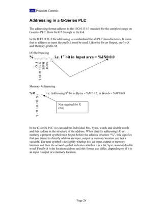
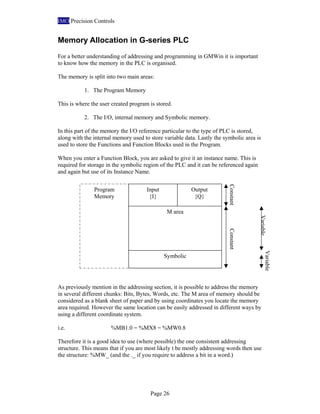
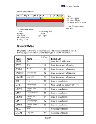
3. IMO Precision Controls
G-SERIES PLC RANGE 1
RANGE OVERVIEW 1
PART NUMBERING 6
INSTALLATION OF IMO GMWIN 7
INTRODUCTION TO GMWIN 10
STARTING A NEW GMWIN PROJECT 12
NAVIGATING GMWIN 15
SETTING UP THE PC CONNECTION FOR PROGRAMMING 16
GMWIN MENU’S 18
PROJECT MENU 18
PROGRAM MENU 18
EDIT MENU 19
VIEW MENU 19
COMPILE MENU 19
ONLINE MENU 20
TOOLS MENU 20
WINDOW MENU 20
HELP MENU 21
PROJECT TREE 22
PARAMETER LIST 22
LIBRARY MENU 23
OUTPUT WINDOW 23
ADDRESSING IN A G-SERIES PLC 24
MEMORY ALLOCATION IN G-SERIES PLC 26
BITS AND BYTES 27
LADDER PROGRAMMING RULES 28
VARIABLE DECLARATION 31
TIME VARIABLES 33
BASIC LADDER LOGIC 34
INPUTS AND OUTPUTS 34
INPUTS 34
OUTPUTS 35
4. IMO Precision Controls
BOOLEAN LOGIC 35
LATCHING CIRCUITS 36
FLIP / FLOP CIRCUIT 36
LADDER PROGRAMMING EXAMPLE 37
BASIC FUNCTIONS 41
MOVE FUNCTION 42
ARITHMETIC FUNCTIONS 42
ADD FUNCTION 43
SUB FUNCTION 43
MUL FUNCTION 44
DIV AND MOD FUNCTION 45
BIT FUNCTIONS 46
AND, OR, XOR FUNCTIONS 46
SHIFT AND ROTATE FUNCTIONS 48
COMPARE FUNCTIONS 48
LT, EQ, AND GT FUNCTIONS 49
FUNCTION PROGRAMMING EXAMPLE 51
BASIC FUNCTION BLOCKS 61
TIMER FUNCTION BLOCKS 62
TOF, OFF DELAY TIMER. 63
TON, ON DELAY TIMER. 63
TP, TIMER PULSE. 64
COUNTER FUNCTION BLOCK 65
CTU, UP COUNTER. 65
CTD, DOWN COUNTER 66
CTUD, UP / DOWN COUNTER. 67
FUNCTION BLOCK PROGRAMMING EXAMPLE 68
MULTIPLE-SOURCE PROGRAMMING 74
GLOBAL VARIABLES 74
MULTIPLE LD PROGRAMS 76
SUBROUTINES 78
DOWNLOADING AND ONLINE OPTIONS 80
COMPILING AND BUILDING 80
GMWIN SIMULATION 81
DOWNLOADING 83
BASIC COMMUNICATION 86
G7 PLC COMMUNICATION DIP SWITCH SETTING 88
5. IMO Precision Controls
PROGRAMMING TUTORIAL EXAMPLE – WASHING MACHINE 90
SPECIFICATION 90
MACHINE I / O 90
WASHING MACHINE CYCLES 90
THE PROGRAM CYCLE 91
BEGINNING TO PROGRAM 91
1. WHITE WASH OR COLOUR WASH IS SELECTED BY A ROTARY SWITCH. 94
2. WHEN THE LID IS CLOSED AND THE START BUTTON IS PRESSED, DETERGENT + WATER
ARE PUMPED IN FOR 1 MINUTE 97
3. THE DRUM ROTATES FOR THE SPECIFIED WASH TIME, DEPENDING ON THE TYPE OF
WASH SELECTED. 99
4. THE DRUM IS DRAINED FOR 1 MINUTE. 100
5. FRESH WATER IS POURED IN FOR 1 MINUTE. 100
6. THE DRUM IS ROTATED FOR THE SPECIFIED RINSE TIME, DEPENDING ON THE TYPE OF
WASH SELECTED. 101
7. THE WATER IS DRAINED FOR 1 MINUTE. 101
8. THE DRUM IS ROTATED FOR THE SPECIFIED SPIN TIME, DEPENDING ON THE TYPE OF
WASH SELECTED. 102
9. THE LID OPEN LAMP WILL OPERATE IF THE LID IS OPENED, AND THE WASH SEQUENCE
CANNOT START. 102
10. IF THE LID IS OPENED AT ANY TIME DURING THE WASH CYCLE, THE CYCLE IS
SUSPENDED AND ONLY CONTINUES WHEN THE LID IS CLOSED AGAIN. 103
COMPILE AND BUILD THE PROJECT 105
SIMULATE THE PROGRAM 105
DOWNLOAD THE PROGRAM TO THE PLC 106
TUTORIAL 1 – IMO GREENHOUSE 109
TUTORIAL 2 – IMO CAR PARK 110
TOPICS COVERED IN THE ADVANCED COURSE 111
IMO Precision Controls
1000 North Circular Rd
Staples Corner
London
NW2 7JP
Tel: +44 (0) 208 452 6444
Fax: +44 (0) 208 450 2274
Email: sales@imopc.com or applications@imopc.com
Web: www.imopc.com
6.
7. IMO Precision Controls
Page 1
G-Series PLC Range
IMO’s G-series PLC range covers the complete scope of automation potential. Within
the IMO PLC range there are three levels. What determines these levels generally is
the users requirements for the application such amount of I/O required. The IMO
range begins with the expandable brick type PLC, the G7 series. To the compact, slot
and rack in the mid-range, the G6 series, through to the high-end G4 series. From the
10 I/O brick style G7 to the 1024 I/O Multi-rack and slot G4 PLC, IMO have got it
covered!
The complete G-Series range is programmed through the IEC61131-3 compliant
software. This is a windows based program allowing the user to program in Ladder
diagram (LD), Sequential Function Chart (SFC) and Instruction List (IL).
Range Overview
G7 G6 G4
Power Supply 110/230Vac or 24Vdc
(E-marked for vehicle low
voltage (12V) operation)
110/230Vac or 24Vdc
(E-marked for vehicle low
voltage (12V) operation)
110 Vac or
230Vac
or
24Vdc
I/O Up to 80 Up to 384 Up to 1024
Analogues Two analogue modules:
2 in, 1 out.
Or 4 in.
Voltage or Current
selectable.
G6F-AD2A 4 analogue
inputs. Selectable, 4-20mA,
0-20mA or 0-10V
G6F-DA2V voltage input
G6FDA2I current input
G4F-AD2A 4 analogue inputs.
Selectable, 4-20mA, 0-20mA
or 0-10V
G4F-DA2V voltage input
G4FDA2I current input
Comm.
options
2 inbuilt RS232 user
configurable ports. RS232
and RS485 options.
Modbus, Profibus (slave),
DeviceNet (slave) FNet,
RNet (IMO comms). User
defined comms.
RS232 and RS485 options.
Modbus, Profibus,
DeviceNet, FNet, RNet
(IMO comms). Ethernet.
User defined comms.
RS232 and RS485 options.
Modbus, Profibus, DeviceNet,
FNet, RNet (IMO comms).
Ethernet, User defined comms.
Expansion Up to 3 maximum but only
2 of the 1 kind. I.e. 2
analogue modules + 1 relay
module.
Maximum rack size of 12
slots.
Non-expandable.
Maximum rack size of 8.
3 expansion racks of 8.
Totalling 32 slots.
Additional
features
HSC, RTC module, 7k
steps, addition memory
module & built in PID.
17k steps. Dedicated MPU
0.5µs. 3-axis open loop
position control module. 3
options of CPU.
32k steps. Dedicated MPU
0.2µs. Floating-point maths &
USB programming port
option. PID module with 8
separate PID loops.
Programming
Software
GMWin. IEC61131-3
(LD/IL/SFC)
GMWin. IEC61131-3
(LD/IL/SFC)
GMWin. IEC61131-3
(LD/IL/SFC)
8. IMO Precision Controls
Page 2
• All of the IMO G-series range uses the same programming software, the
IEC61131-3 compliant: GMWin.
• All the PLC’s can be interlinked and share data within their own dedicated
network.
• The slot and rack PLC’s are modular and very variable. They can be specified
to meet the application more precisely.
• The I/O count doesn’t include the remote I/O units. A maximum network size
of 64 stations, with each possibly having 32 points. (I/O = 2048)
9. IMO Precision Controls
Page 3
The IMO G7 is a very compact block style programmable controller offering
extremely high performance. It is ideal for all applications from process control to
machine control
• Up to 80 I/O
• High speed processing 0.5µsec per step
• Memory capacity 68K bytes
• Conforms to elements of the IEC61131-3 (IL/LD/SFC)
• Built in PID, interrupt, pulse count and input filters
• High speed counter input 16kHz, 8kHz two phase
• RTC option and memory module options
• Fieldbus options FNet (master/slave), DeviceNet (slave) and Profibus (slave)
• Two built in RS232 serial ports one dedicated the other user configurable
• Two analogue modules: 2 / 1 analogue i/o or 4 analogue inputs
• Analogue potentiometer module
• 10 I/O expansion module
• RS232 and RS485 option modules
• Uses the same programming software as G6 & G4 (GM-WIN)
• Conforms to CE and UL
IMO G7
10. IMO Precision Controls
Page 4
The IMO G6 is a compact modular programmable controller offering extremely high
performance. It is ideal for all applications from process control to machine control
• Up to 384 I/O
• High speed processing with dedicated MPU 0.5µsec per step
• Memory capacity 17Ksteps
• Conforms to elements of the IEC1131-3 standard (IL/LD/SFC)
• PID control, computer link, high speed counter and RTC CPU options are
available
• Fieldbus option 1Mbps (FNet), DeviceNet, and Profibus options
• Computer link module for linking up to 32 PLCs to a computer, or to other
devices by easily configuring user protocols
• Wide range of digital and analogue I/O
• High speed counter module
• Conforms to CE requirements
YEAR
GUARANTEE
IMO G6
11. IMO Precision Controls
Page 5
The IMO G4 is a modular programmable controller offering extremely high
performance. It is ideal for all applications from process control to machine control.
• Up to 1024 I/O
• Very high speed processing with custom gate array 0.2µsec per step
• Memory capacity 32K steps
• Conforms to elements of the IEC1131-3 standard (IL/LD/SFC)
• Many special function modules – PID, Analogue timer, High Speed
• Counter, Positioning, Interrupt and A/D and D/A modules
• Wide range of communication options – ENet (Ethernet), FNet Fieldbus),
• Cnet (Computer Link), DNet (DeviceNet) and remote I/O
• Conforms to CE requirements
YEAR
GUARANTEE
IMO G4
12. IMO Precision Controls
Page 6
Part Numbering
At IMO we use an understandable part number where each element has a meaning
and is reused through out the part numbering system, thus making it easy to put
together product requirements
G7 Base models: G M 7 – D _ _ _ A (/ DC – E)
G7 Expansion modules: G 7 _ – _ _ _ _ (– E)
G4/G6 CPU, Base and Power models: G M _ – _ _ _ _
G4/G6 I/O modules: G _ _ – _ _ _ _
R – Relay o/p
T – Transistor o/p
I/O
10
20
30
40
60
DC – 24V
DC power
DC power
supply. E
marked for
vehicle
applications
E – Expansion digital I/O
F- Special function units
L- Communication units
DR -Relay
DT - Transistor
AD - Analogue
AT - Ana pot
CU – Comm. link
RT - RTC
DB - DeviceNet
PB - Profibus
RU - RNet
10A - I/O
2A - 4 A/D
HA - 2 A/D, 1 D/A
EB - RS232
EC - RS485
EA - Comms
I - Digital Input
Q - Digital Output
F - Special function units
L - Communication units
4 – G4
6 – G6
CPU - CPU
PAF - Power AC
PDF - Power DC
B - Base
4 – G4
6 – G6
CPU A – Standard
B – A + RS485 port, PID, RTC
C – A + HSC, PID
G4 C – Floating-point maths
Power A – For use with Standard I/O
B – For use with analogue I/O
C – For use with 12-slot rack
Base 04, 06, 08, 12 M
RY2A –16 Relay o/p
D22A – 16 DC i/p
D24A – 32 DC i/p
A21A –230 AC i/p
A11A - 110 AC input
AD2A – 4 Analogue i/p
TR2A – 16 Trans o/p
TR4A – 32 Trans o/p
HSCA – HSC
POPA – Position control
FUEA – FNet
PUEB – Profibus
EUTB – Ethernet
CUEC – RS485 Comm.
CUEB – RS232 Comm.
Plus many more options
13. IMO Precision Controls
Page 7
Installation of IMO GMWin
GMWin can be obtained on the IMO PLC Software CD or can be downloaded from
the website: www.imopc.com free of charge.
To install double click on the icon GMWIN4.exe and follow the instructions.
A dialogue box showing the welcome message appears. It is required to exit any other
windows application programs that may be running during the installation of
GMWIN.
Click Next to move to the next screen.
14. IMO Precision Controls
Page 8
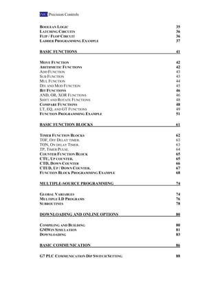
Select the destination folder for GMWin to be installed into. If [Browse] is clicked
then a dialogue box will appear for the path to be inputted. Select the path to install to
or manually write the path in the box and click [OK].
After selecting the path to install, click [Next].
After confirming the path to install into, click [Next] to continue.
15. IMO Precision Controls
Page 9
GMWin will then begin to install on your computer, in the directory specified.
When the install is completed, it is required to restart your computer. You have the
option to restart your computer now or later from the following screen.
Now that the installation is complete and after you have restarted your computer, click
on the GMWin icon to start programming.
16. IMO Precision Controls
Page 10
Introduction to GMWin
GMWIN is a programming and debugging tool for the full range of G-Series PLC’s
(G7, G6 and G4). It is an IEC61131-3 programming compliant environment and with
three different programming languages, IL, SFC and Ladder.
Ladder SFC IL
Programs can be created with clear symbols for easy understanding and easy to follow
menus to create functions and variables alike.
GMWin complies with the standardising of expressing direct variables by I, Q, M
(Input, Output, Memory). The allocation of program variable memory is carried out
automatically or by the user designation. Various data type and kinds can be selected
to match the variables requirements. It is also possible to set the initial value, and add
documentation to every function, function block, constant and variable.
17. IMO Precision Controls
Page 11
The IMO G-Series is a Project based PLC system. In GMWin it is possible to create
several different dedicated programs in different languages to perform specific
routines and have them all related in a Project. As well as Programs there is the option
of Tasks, which can be time or event driven.
A project tree is shown above that details all libraries, tasks and programs included in
a project. Project based programs make duplication and re-use of programs quick and
easy.
It is possible to not only download and monitor programs directly connected to a PC
but also for PLC’s connected in a network. When connected with a PLC it is possible
to monitor the operation, change the mode and edit online. Online editing, allows the
PLC to remain running and the program can be changed. The full PLC mode, error
state and parameters can also be read when connected.
It is also possible to create User-Defined Functions and Function Blocks. This allows
for frequently used bits of code being made into an easy to use and re-useable
graphical function block. There is also the utility to create User-Defined
Communication Protocols, thus allowing obscure and bespoke devices to be
communicated with.
18. IMO Precision Controls
Page 12
Starting a new GMWin Project
To start a new program click on the GMWin icon.
GMWin will appear, with the last project that you were working on, if you did not
close the program down. At the moment GMWin will have no project and look rather
empty, as this is the first run of the software on your computer.
This is located in the path
that is specified during
installation or you can
create a desktop shortcut.
Click start and then All
Programs
This box pops up
whilst the GMWin
program is
initialising.
19. IMO Precision Controls
Page 13
To begin a New Project, either click the New Project icon or select the option from
the drop down Project menu.
In this first menu we can enter the project details and where the project folder is going
to be created. We must select the PLC we are going to use and we have some
documentation options.
20. IMO Precision Controls
Page 14
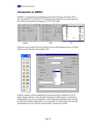
Clicking [Finish] will complete the set up process and return you to the main Window
with a fuller Project to begin programming.
The next stage is to
define the first
program. This can be
edited later and even
removed but initially
this must be set up.
The program will
initially be called
noname.src, but to
modify this, simply
highlight the area
shown and enter a
name that has more
meaning to your
application.
Next we have to select
what language we are
going to write the
program in. The
default is ladder.
SFC, LD and IL will
be discussed in more
detail later.
There is also an
opportunity to add
further documentation
notes.
21. IMO Precision Controls
Page 15
Navigating GMWin
GMWin is a “windows” based programming environment and it can be daunting at
first with the amount of information on offer. The programming environment can be
customised to your personal preference, with windows an optional buttons being
selectable.
Output window. In this window
error messages and compile
warnings can be found
Programming
window. It is
here where the
ladder logic is
entered
Variable table. The
table builds up as
the more variables
are used in the
program.
Ladder
logic
functions
(When
programming
in ladder)
Project
tree
Project, parameter
& library tabs.
Connection status
22. IMO Precision Controls
Page 16
Setting up the PC connection for programming
The most important thing to do first is to ensure that the correct communication port is
selected in GMWin to connect with a PLC. This is particularly important if you are
using a USB to Serial converter.
It is possible to locate your computers communication ports using the Device
Manager in Windows Control panel. (Control Panel: System, Hardware; Device
Manager).
To ensure that the correct port is selected in GMWin go to the option menu in the
Project drop down list.
This computer has a
serial port addressed
on communication
port COM1.
There is a USB
option with the G4
series CPUC
Programming
port selection.
Drop down
tab
Select the Connection Option tab.
The Device Manager can be
found in the Control Panel,
System, Hardware.
Your IT manager should be
consulted before altering
System configurations.
23. IMO Precision Controls
Page 17
The standard method of connection is RS-232C; this is a standard 3 wire, 9 pin D-type
connector crossover cable (KIC-50A). Select the communication port that you are
going to use from the drop down list.
24. IMO Precision Controls
Page 18
GMWin Menu’s
Project Menu
The project menu has the options required to manage the complete project.
Program Menu
This menu operates the options required for the programs in a project.
Starting a new project, opening an
existing project, saving and
uploading from a PLC (to be
discussed latter).
Project bundles are the best method
for transporting GMWin PLC
projects. It collates all the files into
one easy to transfer .MUK file.
Print options
GMWin options
Previous projects created.
A GMWin project is made
up of two types of files. A
.prj file that contains the
project information and at
least one .src source file
that contains the program
information.
25. IMO Precision Controls
Page 19
Edit Menu
In this menu there are the options to edit the programs.
View Menu
Using the options in this menu you can customise what windows you want to view.
Compile Menu
This menu is used to build and compile the program written, ready for downloading it
into the PLC.
In this menu the
options can be
found to edit
programs.
Ladder logic
programming tools
(discussed later)
Select or deselect to
view the Project and
output window
View the documentation
added with the memory
address
There is also the option to
check the program for
duplicated coils, memory and
I/O locations used.
26. IMO Precision Controls
Page 20
Online Menu
This menu has the options for connection with the PLC. In this menu we can read and
write programs to the PLC. Check the status of the PLC, enable communications and
reset errors.
Tools Menu
The simulation tool can be found in this menu. This is a useful tool to test the project
without connecting a PLC.
Window Menu
This window allows you to view the different programming windows in different
ways.
Connecting and writing to the PLC
Checking the PLC mode. Can relate
to the PLC dipswitch position
PLC information. I/O cards used,
communication protocols engaged.
Online editing facility, allows editing
of the PLC program in the PLC
whilst still running.
27. IMO Precision Controls
Page 21
Help Menu
In the help menu you can access the help function and IMO website. Please note that
the language settings require windows to have the Far East and Asian files installed.
(Control Panel: Regional and Language Settings; Languages; Supplemental Language
Support).
28. IMO Precision Controls
Page 22
Project Tree
The project tree contains the complete detail of the project. In this menu you can view
the variables used, Programs included and task definitions.
Parameter list
Access the PLC’s basic parameters, I/O parameters (the different I/O cards in the slot
and rack PLC’s) and Link parameters (set up the communication protocols).
Project information. Set up
whilst creating the project.
By right clicking the mouse on
any of these folders more options
can be accessed. The properties
can be edited.
Scan programs, constantly read
user programs
Tasks: Conditional programs
Global variables. Used in
multiple program files.
The options will be dealt with in
more detail later.
CPU parameters
I/O module parameters
Communication parameters
29. IMO Precision Controls
Page 23
Library Menu
In this menu you can view, add and delete the libraries that contain the functions and
function blocks used in programming.
Select the library required, and click the open button.
Output Window
The output window displays messages. In it you can find connection information,
error messages and other details.
The error messages direct you to where the issue lies within the program.
To add a library right click on a
folder and select: Add item,
Library.
To view what functions are in
the library click on the + icon
30. IMO Precision Controls
Page 24
Addressing in a G-Series PLC
The addressing format adheres to the IEC61131-3 standard for the complete range on
G-series PLC, from the G7 through to the G4.
In the IEC61131-3 the addressing is standardised for all PLC manufacturers. It states
that to address an input the prefix I must be used. Likewise for an Output, prefix Q
and Memory, prefix M.
I/O Referencing
% _ _ _ . _ . _ i.e. 1st
bit in Input area = %IX0.0.0
Memory Referencing
%M _ . _ i.e. Addressing 9th
bit in Bytes = %MB1.2, in Words = %MW0.9
In the G-series PLC we can address individual bits, bytes, words and double words
and this is done in the structure of the address. When directly addressing I/O or
memory a percent symbol must be put before the address structure “%”, this signifies
that you intend to directly address an input, output or memory location and not a
variable. The next symbol is to signify whether it is an input, output or memory
location and then the second symbol indicates whether it is a bit, byte, word or double
word. Finally it is the location address and this format can differ, depending on if it is
an input / output or a memory location.
SLOT
BASE
X
/
B
/
W/
D/
L
I
/
Q
X
/
B
/
W
/
D
/
L
Not required for X
(Bit)
31. IMO Precision Controls
Page 25
In the Edit Menu there is a drop down option that will aid in calculating memory
locations.
Simply enter the address
and click Execute. The M
Calculator will then break
down the memory address
and how it can be addressed
differently.
32. IMO Precision Controls
Page 26
Memory Allocation in G-series PLC
For a better understanding of addressing and programming in GMWin it is important
to know how the memory in the PLC is organised.
The memory is split into two main areas:
1. The Program Memory
This is where the user created program is stored.
2. The I/O, internal memory and Symbolic memory.
In this part of the memory the I/O reference particular to the type of PLC is stored,
along with the internal memory used to store variable data. Lastly the symbolic area is
used to store the Functions and Function Blocks used in the Program.
When you enter a Function Block, you are asked to give it an instance name. This is
required for storage in the symbolic region of the PLC and it can be referenced again
and again but use of its Instance Name.
As previously mention in the addressing section, it is possible to address the memory
in several different chunks: Bits, Bytes, Words, etc. The M area of memory should be
considered as a blank sheet of paper and by using coordinates you locate the memory
area required. However the same location can be easily addressed in different ways by
using a different coordinate system.
i.e. %MB1.0 = %MX8 = %MW0.8
Therefore it is a good idea to use (where possible) the one consistent addressing
structure. This means that if you are most likely t be mostly addressing words then use
the structure: %MW_ (and the ._ if you require to address a bit in a word.)
Program
Memory
Input
{I}
Output
{Q}
M area
Symbolic
Constant
Constant
Variable
Variable
33. IMO Precision Controls
Page 27
M area (exploded view)
15 14 13 12 11 10 9 8 7 6 5 4 3 2 1 0
1 0
0
0
To address in G-Series:
X = bit M = Memory area
B = byte I = Input
W = word Q = Output
D= Double word
L = long word
Bits and Bytes
Different types of variable information require a different amount of bits to store it.
Below is a guide to what is used for different types of variable information.
<- Bits
<- 1 byte = 8 bits
<- 1 word = 2 bytes
<- 1 double word = 2 words
{…and 2 double words = 1
long word}
Used for memory allocations
16
Word
WORD
Used for memory allocations
32
Double word
DWORD
Used for memory allocations
64
Long word
LWORD
Used in calculations
32
Unsigned Double
integer
UDINT
Used in calculations
8
Unsigned Small
integer
USINT
Used in calculations
16
Unsigned integer
UINT
Used in calculations
64
Unsigned long
integer
ULINT
Floating-point maths
64
Long real
LREAL
Floating-point maths
8
Real
REAL
Used in calculations
32
Double integer
DINT
MSB signals the polarity (0 =+ve)
8
Small integer
SINT
Used in calculations
16
Integer
INT
Used for memory allocation
8
Byte
BYTE
Used for I/O addressing
1
Bit
BOOL
Comment
# of bits
Name
Type
34. IMO Precision Controls
Page 28
Ladder Programming Rules
Before programming it is important to know a few basic rules of the ladder diagram
structure. In this section we will discuss the basic programming rules of ladder logic.
It is important to be aware of a PLC’s scan cycle. This is the order of processing that
the PLC performs. The Scan cycle of a GMWin project is as follows:
1. On operation start the variables are initialised, and a self-diagnosis is
performed.
2. The input conditions are then read in and stored
3. The user program is then sequentially executed.
4. Communications with modules is checked and data shared, variables are up
dated and a self diagnoses is performed again
5. Return to read the input conditions and refresh stored memory.
This process is known as the scan cycle and various factors can effect how quick it is.
I.e. Larger and more complex programs have bigger scan cycle times.
User defined Programs (LD, SFC,
IL)
35. IMO Precision Controls
Page 29
The flow of a GMWin program is sequential from the first row to the last; this means
that Code in Row 1 will be operated on before Row 2. The time difference will be
fractional however it is important to note when using latching circuits and sub
routines.
Up to 30 contacts can be placed on one run, but only one coil per line. Function
Blocks and Functions use 3 contact spaces on a line and can be put anywhere on a run
apart from the first space in a line.
In the GMWin programming environment contacts and coils can be inputted without
naming them. This means that the program structure can be drawn out in full before
assigning variables.
All Rows that have been started must be completed, this means that there must be a
complete horizontal connection between the vertical power-rails otherwise the
program will not compile.
No output coil
No input coil / connection to rail
Incomplete connection
36. IMO Precision Controls
Page 30
A Function only has one output and requires an enable signal whereas a Function
Block doesn’t require an enable and can have several outputs and internal data. When
entering a Function Block the user must define an instance name.
Each Function / Function Block requires a Contact in the first input that a named
Variable or constant at the other inputs. It is possible to create user defined Functions
and Function Blocks.
It is possible to duplicate coils and this will not bring up an error. This could have
been intended however it is an easy mistake to make. With a duplicated coil it will
never be active until all conditions are met.
For example in the ladder logic below, A and B on would usually switch Z on.
However Z has been duplicated and so required all conditions (A, B, C and D) to be
on before being switch positive.
37. IMO Precision Controls
Page 31
Variable Declaration
Variables can be expressed in one of two ways. The first is to give a Name to a data
element using an identifier and the second is to directly assign a memory address /
input or output address to a data element.
Variables can either be entered as contacts/coils/functions or function blocks are
entered or in the variable table.
Right click on the mouse when the arrow is in the table area at the top of the ladder
logic program.
Variable table with variables assigned in the program.
Directly addressing uses the percent sign % followed by the location prefix. The
location prefix contains a location identifier (I, Q, M), followed by a size prefix (X, B,
W, D, L) and completed with an expression indicator (for I and Q, base . slot. Data;
for M, data (according to size prefix). bit of data).
i.e. % I X 0 . 2 . 6 : Input, Bit size, Base 0, Slot 2, Bit 6.
% M W 32 . 7 : Memory, Word size, word 32, bit 7.
When directly addressing
it is possible to add Direct
Variable comments.
38. IMO Precision Controls
Page 32
When naming a variable there is a little more information that has to be inserted.
Variable name:
16 characters,
with no spaces
Normal,
Constant,
Retainable,
Global
Data type:
whether it is
binary, numeric,
time, array, etc
An initial value
to be loaded
into variable on
power up Documentation
comments
Assigning
memory to a
location
VAR: General read / write variable
VAR_CONSTANT: Read only, constant
VAR_RETAIN: Read / write, but keeps
value on power down
VAR_EXTERNAL: Use to declare the
variable as
VAR_GLOBAL
(global variable)
The data type of a variable depends on the
type of data that the variable is representing.
i.e. Integer value, time, binary, etc. This also
is important, as the different types of data
require differing amounts of memory size to
store them.
Here we can allocate the
variable to a memory location.
This is much like the direct
addressing.
39. IMO Precision Controls
Page 33
Time Variables
Time variables are used in Timers for the preset value and need special attention. Data
intended to be entered into timers must use advanced functions to convert to a Time
Variable. This will be discussed further in the Advanced Function section.
Time variables have the prefix of: t#
The value is the entered before ending with the variable with the timing constraint.
i.e. A Timing Value of two days, seven hours, three minutes, twenty seconds and
sixteen milliseconds, would become: t# 2 d 7 h 3 m 20 s 16 ms
The maximum time allowed is T#49d17h2m47s295ms (32 bits of ms unit)
Data can be
set with an
initial value
instead of
zero
Comments for
documentation
This is a 5s On-delay
timer
40. IMO Precision Controls
Page 34
Basic Ladder Logic
All ladder diagram programs contain basic Boolean logic and interlocking circuitry. It
is important to master the basics as complicated programs are made of these simple
programs.
Inputs and Outputs
The inputs and outputs can be inserted by using the Icon bar and click on the desired
icon or by using a hot key.
The inputs and outputs are of a Boolean type and operate as either ON or OFF.
Inputs
Normally Open contact.
Normally Closed contact.
Positive edge triggered contact.
Negative edge triggered contact.
Arrow
mode NO
contact
NC
contact
+ve
edge
contact
-ve
edge
contact
Horizont
al bar
Vertical
bar
NO coil
NC coil
Set
coil
Reset
coil
+ve edge
coil
+ve edge
coil
Function
Function
Block
Sub
return
Jump
Sub
call
41. IMO Precision Controls
Page 35
Outputs
Boolean Logic
Boolean logic deals with binary data, (ON or OFF), with knowledge of some basic
Boolean logic circuits most events can be accounted for and controlled.
AND Gate: Z = A AND B
OR Gate: Z = A OR B
NOT Gate: Z = NOT A
Normally Open relay coil.
Normally Closed relay coil.
Set relay coil
Reset relay coil
Positive edge triggered relay coil.
Negative edge triggered relay coil.
42. IMO Precision Controls
Page 36
Or
Latching Circuits
A latching circuit holds an output high when the input has been removed. There are
two methods of latching circuit: Circuitry latch and Set / Reset coils.
Circuitry latch using the output as an interlock.
Using S R relay coils.
Flip / Flop Circuit
A flip-flop circuit toggles the output. The first input pulse will set the output high and
the second input pulse will reset.
Flip-flop circuit diagram.
1st
Pulse – Switches On the output Z.
43. IMO Precision Controls
Page 37
The output Z is latched ON.
The 2nd
input pulse resets the output and switches Off Z.
Ladder Programming Example
Design a simple ladder circuit using a logical AND gate and an OR Gate to create a
basic interlock.
First open GMWin and start a new project.
Select the Normally Open (NO) contact icon in the toolbox and click the right
button of the mouse into position row ‘0’ and column ‘1’ in the LD window
Next Select a Normally Closed (NC) contact icon in the toolbox and click the
right button of the mouse on position row ‘0’ and column ‘2’ in the LD window
Next Select a normally open coil icon in the toolbox and click the right button of
the mouse on position row ‘0’ at the far right hand side. You will see that it the line is
automatically created so that it is connected across to the inputs.
44. IMO Precision Controls
Page 38
Select the Normally Open (NO) contact icon in the toolbox and click the right
button of the mouse on position row ‘1’ and column ‘1’ in the LD window
Select the Up line connection icon in the toolbox and click the right button of the
mouse between row ‘1’ and row ‘0’and column ‘1’ in the LD window.
Now that the diagram has been entered we can enter the variables. Double click on the
contacts and coils with the right mouse button to enter the Variables menu.
Click
Add to
enter new
variables
45. IMO Precision Controls
Page 39
Name Type Address Comment
Enable BOOL %IX0.0.0 1st
input to enable
Reset BOOL %IX0.0.1 2nd
input to reset
Motor BOOL %QX0.0.0 Motor on 1st
output
Keep adding variables until you have a variable menu like below. To assign variable
to the contacts and coils, Double click on the contact or coil and simply select the
variable from the menu and press OK.
The program should now look like the one below.
Enter the
variable
data. Then
click done
when
complete
47. IMO Precision Controls
Page 41
Basic Functions
There are two methods of entering a function into a program: Selecting the Function
icon or pressing the hotkey. Both methods attached the Function icon onto the mouse
arrow and then simply click it into the diagram.
Select the function you want and enter the settings required. Press OK once complete.
The Function menu will open for you to select the
desired function.
Function selection
48. IMO Precision Controls
Page 42
Move Function
A frequently used function. Used to move data from one memory location into
another location.
When the Enable input goes high, the data in A will be moved to memory location
%MW123.4.
Arithmetic Functions
The PLC can perform all mathematical functions. However the only PLC CPU that
can perform true floating-point maths is the G4 CPUC. This means that the result of
an arithmetic function will return an integer, unless using a GM4-CPUC.
Arithmetic functions are entered as any other Function, however you can select the
number of inputs required. You can select the desired function easier by selecting the
arithmetic tab, which lists only those particular functions.
All arithmetic
functions are
available in a
sub menu for
ease of
selection.
Available
functions
include Add /
Sub / Mul / Div
/Mod
49. IMO Precision Controls
Page 43
Add Function
The Add function performs addition on up to 8 variables.
The Addition Function can have up to 8 eights. Select the number of inputs required
for the function and click ok. Below is an example of a 2 input Add function.
Sub Function
The Sub function, subtracts one variable from another.
The Subtraction function can only have two inputs.
C = A + B
When enable goes
high A is Added to B
and stored in C.
50. IMO Precision Controls
Page 44
Mul Function
The multiplication function can up to eight inputs selected.
The example below is a three input is multiplication function.
C = A – B
When Enable is set high, B
is Subtracted from A and
stored in C.
D = A x B x C
When the enable signal is active
the calculation is performed (A x
B x C) and stored in D.
51. IMO Precision Controls
Page 45
Div and Mod Function
The divide function can only have two inputs and returns only a whole number. The
Mod function calculates the remainder and returns the value as in integer.
C equals A divided B and D equals the remainder of A divided by B.
52. IMO Precision Controls
Page 46
Bit Functions
Bit functions and functions that manipulate the fundamental bits of data.
AND, OR, XOR Functions
These functions can also be performed using ladder logic. See Basic Ladder Logic,
Boolean Logic.
Depending on the type of Function,
they can have a minimum of two
inputs and an enable signal.
The bit functions include Boolean
Logic Functions like AND, OR, and
XOR but also include Rotate and
Shift functions like ROR, ROL,
SHR and SHL.
53. IMO Precision Controls
Page 47
2 Input Exclusive OR
Z = A XOR B
4 Input AND Gate
Z = A AND B AND C AND D
3 Input OR Gate
Z = A OR B OR C
54. IMO Precision Controls
Page 48
Shift and Rotate Functions
Shift and rotate functions operate on byte and word variable kinds. They perform bit
multiplication and division.
Compare Functions
Comparison functions are used to evaluate data.
GE Greater or Equal
GT Greater Than
LE Less or Equal
LT Less Than
EQ Equal
MID Takes the middle part of a
character string.
MUX Selection of 1 from a multiple
of inputs.
SEL Select one of two inputs
55. IMO Precision Controls
Page 49
LT, EQ, and GT Functions
If A is Greater Than B then the
output Z will be high.
56. IMO Precision Controls
Page 50
If A Equals B then the output Z
will be High.
If A is Less Than B then the
output Z will be High.
57. IMO Precision Controls
Page 51
Function Programming Example
Write a simple Move, Comparison and Add function program.
Select a Function by clicking the icon in the toolbox with the right button of the
mouse and put into position row ‘0’ in from the first column.
The Function menu will then pop up.
The Function is now in the ladder diagram. Note this particular function requires three
rows.
Now insert a NO contact in row 0, column 1.
Either search
through the
functions or
if you know
the desired
function
name, enter it
in the box.
Type MOVE
and then
click OK.
58. IMO Precision Controls
Page 52
To insert a new variable at the IN1 of the MOVE function, double click the right
mouse button in the space to the left of IN1. This will open up the variables menu.
The variable is now entered at the function. Note that the Functions Function Blocks
only require the first input to be a contact and the rest of the inputs are named
variables.
Click Add to
insert a new
variable.
We are going to
read the inputs of
the PLC as a
word. So we
need to change
the elementary to
WORD.
Click OK when
the details have
been entered
59. IMO Precision Controls
Page 53
Double click the right mouse button on the input contact and enter the variable
“Enable” as a Boolean and Auto allocated.
The input side is now set up on the function.
Now to set up the output of the MOVE function. Double click the right button on the
mouse in the space to right of the OUT on the MOVE function. This will bring up the
variable menu and we need to add a variable for the output, for data to be moved to.
Enter the
details and
click OK.
60. IMO Precision Controls
Page 54
Insert a NO coil off the ENO output of the MOVE function. It is not always necessary
to do this however for this example we require it. Name the variable Compare, the
type will be Boolean and auto allocate it.
Now that the move function has been set up we can continue the program with setting
up a compare function. We want to compare the DATA_IN to a fix value, if
DATA_IN is greater or equal to the value 100 we want the output to go high. In this
case we are going to use the function GE.
Select a Function by clicking the icon in the toolbox with the right button of the
mouse and put into position row ‘3’ in from the first column.
Enter the
data and
click OK.
61. IMO Precision Controls
Page 55
Enter a NO contact at EN and assign it to the variable COMPARE. Using the right
mouse button and double click in the space to the left of IN1, assign the variable
DATA_IN.
Type GE in
the text box
and set the
input number
to 2.
Click OK
when the
details have
been entered.
62. IMO Precision Controls
Page 56
Double click the right mouse button in the space to the left of IN2 to bring up the
variables menu.
Highlight and delete the % symbol to enter a constant value of 100. Click OK when
complete.
63. IMO Precision Controls
Page 57
Now assign a NO coil to the output OUT of the GE function, and add a new variable
to assign to the coil.
Enter a new
variable named
GREATER, of
element type
BOOL and
auto allocate it.
Click OK,
when done.
64. IMO Precision Controls
Page 58
Now we want to set up the Add function select a Function by clicking the icon in
the toolbox with the right button of the mouse, put the function into position row ‘7’
in from the first column.
Type Add
in the text
box and set
the number
of inputs to
2.
Click OK
when
completed.
65. IMO Precision Controls
Page 59
With the Add function we want to Add 1 to the outputs of the PLC every time the
GREATER output is high.
Double click the right mouse button to the left of the input IN1 of the ADD function.
Add a new variable called DATA_OUT, make the element type an INT (integer) and
allocate the memory to %QW0.0.0. If we make the output the same as the input, each
time the output is triggered the input will increment. Therefore double click the right
mouse button in the space to the right of the OUT output of the ADD function.
Double click the right mouse button in the space to the left of the input IN2 and enter
the constant 1.
Click OK
when
done
66. IMO Precision Controls
Page 60
Finally we need to set up the enable to trigger the ADD function when variable
GREATER is high. However we only want one pulse per GREATER trigger,
therefore we will use a leading edge pulse contact.
Select the rising edge pulse contact icon in the toolbox and click the right button
of the mouse on position row ‘1’ and column ‘1’ in the LD window
Now the program is complete, try simulating the program to see how it works.
67. IMO Precision Controls
Page 61
Basic Function Blocks
A Function Block (FB) can have several outputs and contains data inside. A Function
Block is required to be declared on entry.
Enter a Function Block by clicking on the hotkey or selecting the icon.
When you select the Function Block, it attaches to the mouse arrow. Click it into the
programming area and the Function Block selection menu pops up.
Assigning an
instance name
Assigning the
variable type
Function
Block
libraries
Available
functions
Function
Block
information
68. IMO Precision Controls
Page 62
Timer Function Blocks
The three basic Timer Function Blocks are: TOF, Off-delay timer, TON, On-delay
timer and TP, Pulse timer.
When the timers have been inserted GMWin creates the outputs to use elsewhere in
the program.
Timer Function Blocks create the outputs .Q and .ET. The .Q represents the output
state of the timer and the .ET represents the Elapsed Time.
69. IMO Precision Controls
Page 63
TOF, Off Delay timer.
TON, On delay Timer.
When enable goes high and the timer output is set high,
when the enable then goes low the timing begins and the
output remains high until the timers’ time has elapsed.
When the enable goes high the timer begins to count. The
output will go high when the timing has elapsed. The output
will remain high until the Enable input has been removed.
70. IMO Precision Controls
Page 64
TP, Timer Pulse.
When the enable signal is set high the timing begins,
the output will be set high for the duration of the
timing. Once the timing has been completed the
output goes low and the timing begins again. The
output will pulse high-low whilst the Enable signal
is on.
71. IMO Precision Controls
Page 65
Counter Function Block
There are three basic types of Counter Function Blocks: CTU, CTD, CTUD.
The CTU Counter is an Up counter, the CTD is a Down Counter and the CTUD is an
Up / Down counter (it is a combination of a CTU and CTD).
When a Counter Function Block is inserted GMWin creates the outputs for use in the
program.
All counters have a .CV output, this is the Current Value. The Up and Down counters
have a .Q output for when the counter is output is high. Finally the Up / Down
Counter has an output state for both Low count condition and a High output condition.
CTU, Up counter.
72. IMO Precision Controls
Page 66
CTD, Down Counter
The down counter works in the opposite way to the Up
counter. There is no reset input but a Load input, when
high this loads the counter with the Preset Value. The
down input will then count down from the PV value
loaded and the counter will go high when CV is equal
to zero.
The Counter will count up every Up pulse input.
The output of the counter will go High when, CV
is equal to PV. The Current value will continue to
go up on every Up input pulse and the output .Q
will remain high until the Reset input is triggered.
This then resets the Counter CV back to zero and
the output will go off.
73. IMO Precision Controls
Page 67
CTUD, Up / Down Counter.
The Up / Down Counter is a combination of the two
previous counters (CTU and CTD).
The CTUD has all the inputs of the CTD and CTU,
plus it has an Up condition output .QU and Down
condition output .QD. The Up condition output will go
high when CV is equal to the PV value. It will then
remain high whilst CV is greater than or equal to PV.
The Down condition output .QD will go high when
CV is equal to zero.
The Up input increments CV, whilst the Down input
decrements CV. The Reset input, resets CV back to
zero, whilst the Load input, loads the Preset Value
(PV) into the Current Value (CV).
74. IMO Precision Controls
Page 68
Function Block Programming Example
Design a simple timer and counter program that will count the timer output.
Select a Function Block by clicking the icon in the toolbox with the right button
of the mouse and put into position row ‘0’ in from the first column.
The Function Block menu will pop up.
Insert a NO contact at the IN input to the timer and Add a variable. Name the variable
Enable and allocate the address to %IX0.0.0 . You will notice that there are some
variables that have been created already, TIMER1.Q and TIMER1.CV. These are the
output and current value of the timer. They can be used elsewhere in the program
simply by assigning them to inputs and contacts.
Either search
through the
functions or
if you know
the desired
function
block name,
enter it in the
box.
Type TON
into the text
box for an on
delay timer
Give the
timer the
instance
name
timer1
and click
OK.
75. IMO Precision Controls
Page 69
Double click the right mouse button in the space to the left of the input PT. This
brings up the Variable menu. We are now going to enter a Preset Time for the timer.
Delete the % sign and insert the data, t#5s. This is the prefix for a five seconds time.
76. IMO Precision Controls
Page 70
There is no need to allocate output variables as they have already been created:
TIMER1.CV and TIMER1.Q
We now want to insert a Counter, select the Function Block icon by click on it in
the toolbox with the right button of the mouse and putting it three columns to the right
if the timer function block.
77. IMO Precision Controls
Page 71
As with the timer function block the counter function block automatically creates
outputs, in the case: IP_COUNT.Q and IP_COUNT.CV
These outputs can be used elsewhere in the program.
We now need to connect the output TIMER1.Q to the UP input of the counter. Select
the horizontal line connection icon in the toolbox and click the right button of the
mouse to connect the spaces between the timer function block and counter function
block.
Either search
through the
functions or
if you know
the desired
function
block name,
enter it in the
box.
Type CTU
into the text
box for an
UP counter
Give the
timer the
instance
name
IP_COUNT
and click
OK.
78. IMO Precision Controls
Page 72
Now we need to assign variables to the inputs on the counter function block. Input R
is a reset input of type BOOL and input PV is the preset value that the counter will
count up to, it is of type INT.
Double click in the space to the left of input R, with the right mouse button and add a
new variable called RESET.
Double click in the space to the left of input PV, with the right mouse button and add
a new variable called PRESET.
Assign the
variable to
the memory
address
IX0.0.0 and
click OK
79. IMO Precision Controls
Page 73
Next Select a normally open coil icon in the toolbox and click the right button of
the mouse at the output Q of the counter. Directly address this output to %QX0.0.0 by
double clicking the right mouse button on the coil to open the variable menu.
When the ENABLE input is switch ON the timer will count to five seconds. When 5s
has elapsed the timer output Q will go high, this will trigger the counter input and the
counter current value will be incremented by one. When the counter current value
reaches ten, the counter output Q will go high and trigger the coil output %QX0.0.0
Leave the
variable as
Auto
allocated but
give it an
initial value
of 10. Click
OK to
complete.
80. IMO Precision Controls
Page 74
Multiple-Source Programming
Global Variables
Global Variables can be used in multiple Programs within a Project, unlike regular
variables.
One way to declare a Global Variable is to assign it to VAR_EXTERNAL type, when
entering the variable in a program.
You will know see that the
Resources Global menu in
the project tree has a Global
variable declared.
81. IMO Precision Controls
Page 75
Another method is to double click on the RESOURCES GLOBALS menu in the
project tree and ‘Add’ a Variable as usual.
Enter a Variable as
normal, however there
are a couple of different
Variable Kinds to select
from.
Var_Global: normal
variable.
Var_Global_Constant:
Constant global variable
Var_Global_Retain:
Global variable with
power down retain.
82. IMO Precision Controls
Page 76
Multiple LD Programs
It is possible to have more than one program in a GMWin Project. This allows the
programmer to have a dedicated program to perform a specific function, for example
one program can control the communications and another to control the logic of a
machine process.
Variables declared in one program will not be available in other programs unless
declared as Global.
To enter a new program right click on the project tree and select Add Item, Program.
A Program must be
given a name and an
Instance name.
The programs will then
be put in order of
instance name.
83. IMO Precision Controls
Page 77
The scan cycle of the Project will process the programs linearly. In this case INST0
will be processed before INST1. However the order can be changed.
Now a blank program has
been created, to select it as
a Ladder Diagram, double
click on it and select the
option.
On selection of
Language, click
OK
Then continue
programming as
before.
To Change the
order of the
Programs, right
click and select
Up or Down
(Program)
84. IMO Precision Controls
Page 78
Subroutines
A Subroutine is a grouping of logic that must be performed given a certain condition.
To use Subroutines the programmer needs to use Sub Call and Return from
commands. A Sub Call command is similar to a Jump command however there are
some subtle differences. A Sub Call function is required to return to where it was
called from and then it the PLC will continue linearly to process code. Whereas a
Jump command skips code to and processing is continued at a given location.
To enter a Subroutine call, select the icon or use the hot-keys short cut.
Subroutine call
to the label
SUB_LABEL
End of main program
Main program
that will
contain all the
Subroutine
calls.
Subroutine call locates to the
label SUB_LABEL
Return command to return
to the main program
85. IMO Precision Controls
Page 79
To enter a Return call, select the icon or use the hot-keys short cut. A return call
doesn’t require a coil to operate it, simply enter it at the end of the subroutine (as
shown in the example).
To enter Comments, an End of Main Program statement or a Label, double click on a
Row number and a menu will pop up.
Select the desired option and enter the relevant data.
Then double click on the
SCAL function call and
enter the Label to go to.
Either select a pre-registered
label or enter a Label
directly
Enter a new label or select
from the list
Enter the program comments to be seen in
the ladder diagram.
86. IMO Precision Controls
Page 80
Downloading and Online Options
Compiling and Building
Prior to downloading the Project needs to be compiled and built. This prepares the
Project for downloading to the PLC and checks for any errors.
The compile options prepare the programs for
downloading. The programs are checked for errors
Compile: Makes just the one program you are currently
working on.
Build All: Makes the complete project.
When the program has
compiled it informs the user of
any errors or warnings.
Errors will stop the program
from operating, whereas
warnings just inform you of
potential issues but do not
impact on downloading the
program.
Clicking the
Compile option
brings up this
message
87. IMO Precision Controls
Page 81
The compile messages are shown in the output window and can be cycled through
using the message buttons in the Compile drop down menu.
GMWin Simulation
In GMWin there is a powerful simulation tool to verify your program without
connecting a PLC. As GMWin is designed for use with the complete range of G-series
PLC’s the simulator looks like a slot and rack type PLC.
To open the PLC Simulator click on the icon with the right mouse button or
select the simulator option from the Tools menu.
Clicking the Build
All option brings up
this message
Building the whole
program, links the entire
project and shows the
memory used.
It shows the Program
memory size, Data size
and upload file size,
along with the
maximums it shows the
percentage used.
88. IMO Precision Controls
Page 82
When the simulation software is started the project is built. Click OK to continue with
the simulation.
The simulation PLC is similar to a
G4 or G6 PLC. When simulating a
G4 or G6 program it is important to
insert the I/O modules as addressed
in the program. With a G7 program
there will be a default 60 I/O card in
slot zero and then the user can add
modules where necessary.
i.e. %IX0.0.0 = slot 0
%QX0.2.3 = slot 2
To put the PLC in
RUN mode use the
right mouse button
to switch the dial
from STOP (S) to
RUN (R). Click on
the circle above R.
To insert a digital input, digital output, analogue
input or analogue output module click the right
mouse button and drag the module to the desired
slot location. To remove a module click the right
mouse button and drag it to the trash icon
The inputs in
the slot are
square and the
outputs are
round. When
ON the inputs
go green and
outputs go red
89. IMO Precision Controls
Page 83
The simulated PLC will stay on top of all program, however you can change this
option by left click the mouse on the blue bar at the top.
When the PLC is in RUN mode the program power rails are in blue as are the contacts
and coils that are ON.
When the variable is ON the variable name also changes colour from black to RED.
Downloading
Once the program has been compiled it is ready to be downloaded. However there is a
button that will compile the program, build the project and download to the PLC.
This button will Compile, Build,
Download, put the PLC in RUN
mode and monitor the program.
Un-tick here, for
the simulation
PLC not to appear
above all the
program,
Enable = %IX0.0.0,
is ON and shown in
green.
Motor = %QX0.0.0,
is ON and shown in
red
90. IMO Precision Controls
Page 84
The connect button in the toolbar at the top will now be appear pressed
To connect to the PLC,
either use the Connect
option on the Online menu
or press the connect button
on the Basic buttons.
When connected the
greyed out options will
become available.
If there is no program in the PLC or the
security option has been selected then
this message will pop up when the user
connects to the PLC.
The grey-out online options are now
available.
Once connected to the PLC it is now
possible to:
• Write and read to the PLC.
• Switch the mode between
RUN, STOP and PAUSE.
• Write and Read to the Flash
memory.
• Check the PLC information,
useful for if an error occurs in the
PLC.
• Check the I/O modules
connected.
• Enable the High Speed
Networks.
• Edit the program ONLINE.
This allows the user to make
91. IMO Precision Controls
Page 85
Once the program is ready to be downloaded, select the Connect + Write + RUN +
Start monitor button to program the PLC.
The user is then
prompted for what
they want to
download.
For security, if you
do not wish for
anybody to be able
to upload your
program back off the
PLC, un-tick the
upload option.
The project is then Compiled and Built before
being downloaded to the PLC
Now that we are online and monitoring the program we can
see that the power rails are on (shown in blue) and we can
monitor the variable data, this can be seen in green. When a
contact or coil is power they will appear in blue.
92. IMO Precision Controls
Page 86
Basic Communication
For communications with the IMO HMI’s range (both PMU and MI-text terminal),
the basic communication parameters will need to set. The communication parameters
menu can be found in the parameter tab.
The parameters need to be set to match the HMI. Generally the HMI will be the
master and the PLC the slave.
The key settings to ensure communication with the HMI are that the Baud rate, Stop
bit, Start bit, Data bit and Station number. They all must match what has been entered
in the HMI’s communication settings.
93. IMO Precision Controls
Page 87
HMI is
generally
the
master,
so ensure
PLC is
slave
For communication
with the HMI’s this
is always set as
RS232 / 422 /485
94. IMO Precision Controls
Page 88
G7 PLC Communication Dip Switch Setting
On the G7 PLC the 9 pin socket is two communication ports in one, RS232 and at the
flick of a dip switch RS422/RS485.
When the Cnet dip switch is in the on position the G7 PLC can communicated on a
Cnet protocol. This is a RS422 / 485 protocol and has the following wiring
When the Cnet switch is
in the off position the
Cnet communication is
not enabled and the
Loader protocol can be
used. Loader protocol is
RS232.
The Cnet dip
switch is located
on the output
side of the PLC
along with the
ROM mode
switch.
95. IMO Precision Controls
Page 89
With the G7 PLC it is possible to communicate to both the HMI and PC. The Cnet dip
switch needs to be in the on position and the HMI will communicate on Cnet protocol,
whilst the PC will remain on Loader.
The advantage of this setting is that the PLC can be monitored whilst it is still ‘live’
communicating with the HMI.
RS232 Loader
Communication.
PC –PLC
2 –3
3 – 2
5 – 5
RS485 Cnet
Communication.
PLC –HMI
4 –3
7 – 2
5 – 5
96. IMO Precision Controls
Page 90
Programming Tutorial Example – Washing Machine
Specification
Design a GMWin project with a ladder program to run a simple washing machine
program. The washing machine has four inputs and six outputs. The washing machine
will run two wash cycles: White wash and Colour wash.
Machine I / O
INPUTS OUTPUTS
1. Start Detergent + Water In
2. White Wash Fresh Water In
3. Colour Wash Water Drain
4. Lid Closed Drum Rotate
5. Spin Dry
6. Lid Open Lamp
Washing machine cycles
The White Wash or Colour Wash is selected by a rotary switch (i.e. only one type can
be selected).
Wash Time Rinse Time Spin Time
White Wash 10 minutes 5 minutes 4 minutes
Colour Wash 7 minutes 4 minutes 3 minutes
97. IMO Precision Controls
Page 91
The Program Cycle
1. White Wash or Colour Wash is selected by a rotary switch (i.e. only one type
can be selected).
2. When the lid is closed and the start button is pressed, Detergent + Water are
pumped in for 1 minute.
3. The drum rotates for the specified wash time, depending on the type of wash
selected.
4. The drum is drained for 1 minute.
5. Fresh water is poured in for 1 minute.
6. The drum is rotated for the specified rinse time, depending on the type of wash
selected.
7. The water is drained for 1 minute.
8. The drum is rotated for the specified spin time, depending on the type of wash
selected.
9. The lid open lamp will operate if the lid is opened, and the wash sequence
cannot start.
10. If the lid is opened at any time during the wash cycle, the cycle is suspended
and only continues when the lid is closed again.
Beginning to Program
It is a good programming practice to map the known variables to addresses in the PLC
before starting to program.
INPUTS Address OUTPUTS Address
Start
%IX0.0.3
Detergent + Water In %QX0.0.0
White Wash
%IX0.0.5
Fresh Water In %QX0.0.1
Colour Wash
%IX0.0.6
Water Drain
%QX0.0.2
Lid Closed
%IX0.0.7
Drum Rotate
%QX0.0.3
Spin Dry %QX0.0.4
Lid Open Lamp %QX0.0.5
Open GMWin and create a new project.
Double click on the icon to start GMWin.
98. IMO Precision Controls
Page 92
Set up a new project
Project
Name
Washing_Machine
Base Type G7
Writer Your name
Comments Washing machine
tutorial
Enter the above details and
click Next
Highlight “noname00.src”
and type: Washing_program.src
Click Next when
complete
99. IMO Precision Controls
Page 93
Now the project has been made we are ready to create a Program.
Select Ladder (LD)
and click Finish.
100. IMO Precision Controls
Page 94
1. White Wash or Colour Wash is selected by a rotary switch.
Select the NO contact icon in the toolbox and click the left button of the mouse
on position row ‘0’ and column ‘1’ in the LD window.
Assign a variable name to the NO contact and allocate the relevant IP address to the
variable name. (As mapped out before programming)
The same timer can operate from different preset times. This can be achieved by
moving a time literal into a variable, which can then be used as a preset time.
Select in the toolbox using the mouse and insert a MOVE function after the NO
contact.
101. IMO Precision Controls
Page 95
Double Click on the area to the left of IN1. The Variables dialog box will be
activated. Enter the time expression for 10 minutes.
102. IMO Precision Controls
Page 96
Double Click on the area to the right of OUT. Enter the Variable name
WASH_TIME, as a TIME Data type.
On the rising edge of the NO contact activation the time value of 10 minutes (T#10M)
is moved into the variable named WASH_TIME with a time data type.
The other two variables for the White Wash Cycle can be linked in series to the NO
contact.
103. IMO Precision Controls
Page 97
Repeat for the Colour Wash Cycle. Move the relevant time values into the
WASH_TIME, RINSE_TIME and SPIN_TIME Variables.
2. When the lid is closed and the start button is pressed, Detergent
+ Water are pumped in for 1 minute
Create a latch using the lid closed and start inputs. Create three variables,
LID_CLOSED, START and START_LATCH. LID_CLOSED and START are
allocated to the relevant inputs and START_LATCH is auto allocated.
Insert an output coil by clicking on the icon with the mouse and inserting it to the
program on the right hand side. The same Add / Edit Variables menu will pop up so
that you can name the variable.
Use the START_LATCH bit to operate an ON delay timer for 1 minute.
To insert an On Delay Timer select the Function Block icon using the mouse.
104. IMO Precision Controls
Page 98
Name the TON timer as T1. Enter the time value T#1M as the Preset Time (PT). Use
the T1 timer output bit, T1.Q to break the START_LATCH.
Also use the START_LATCH bit, in series with a NC output bit of the T1 timer,
T1.Q, to operate the Detergent and Water in output, DET_WAT_IN assigned to
%QX0.0.0.
To insert a Normally Closed (NC) coil click on the icon with the mouse and insert
it into the program where required.
Select TON from
the list and enter
the instance
name as T1.
105. IMO Precision Controls
Page 99
Link the START bit in series with the colour/white wash selection at the start of the
program. The selection of program will only happen at one point in the wash cycle. If
the wash selector is changed during the program, the settings for the current cycle will
remain the same and not change until the next cycle.
3. The drum rotates for the specified wash time, depending on the
type of wash selected.
After the detergent and water have been pumped in for 1 minute, the output bit from
the T1 timer, T1.Q, can be used to start the drum rotation timer and output. Create a
latch called WASH_LATCH, and use this latch to operate the timer and the output.
With two options for the length of time that the drum rotates, Colour and White wash,
the WASH_TIME variable is used as the Preset Time (PT) for the On delay timer.
106. IMO Precision Controls
Page 100
4. The drum is drained for 1 minute.
The resulting bit from the wash timer, T2.Q, is used to latch a bit to operate the drum
drain output and a 1 minute delay.
5. Fresh water is poured in for 1 minute.
The resulting bit from the drain timer, T3.Q, is used to latch a bit to operate the fresh
water in output and a 1minute delay.
107. IMO Precision Controls
Page 101
6. The drum is rotated for the specified rinse time, depending on
the type of wash selected.
The resulting bit from the fresh water timer, T4.Q, is used to latch a bit to operate the
drum rotate output and the RINSE_TIME delay. As the DRUM_ROTATE output is
already used in row 17, and can only be assigned to an output coil once in the
program, the drum rotate condition is linked in parallel with the output on row 17.
7. The water is drained for 1 minute.
The in the program resulting bit of the rinse timer, T5.Q, is used to initiate the drain
timer and output. Again the drain output has been used previously so the initiating bit
is used in parallel in row 24.
108. IMO Precision Controls
Page 102
8. The drum is rotated for the specified spin time, depending on
the type of wash selected.
9. The lid open lamp will operate if the lid is opened, and the wash
sequence cannot start.
Use a NC condition of the lid switch input to operate an output lid open indicator.
109. IMO Precision Controls
Page 103
10. If the lid is opened at any time during the wash cycle, the cycle
is suspended and only continues when the lid is closed again.
The lid switch input could also be placed in series with any line where an action is
performed. This will stop the cycle at the point where the lid is opened and only
restart again when the lid is closed.
To ensure the START button does not restart the program again during the cycle,
insert a NC contact on row 8 after the T1.Q NC contact. Create a new variable
RUNNING and assign to the contact.
Insert a line and add a NO contact with variable T1.Q. Add a set coil with the variable
RUNNING.
After the last time, T7, add a NO contact T7.Q operating a reset coil with the variable
RUNNING.
Place the RUNNING bit in series with the recipe selection, to inhibit changes to the
preset time during the cycle.
110. IMO Precision Controls
Page 104
Rung comments can be added by double clicking on the row number on the left power
rail, selecting the rung comment option and entering the comment in the dialog box.
Enter the comment and press ok
Double
clicking
brings up this
menu option.
Select Rung
comment and
click OK
111. IMO Precision Controls
Page 105
Compile and Build the Project
Once the program has been written has been written Compile the program by clicking
on the icon with the mouse.
Simulate the Program
To simulate the program click on the icon with the mouse. This will
automatically build the program and if there are no errors open up the simulation
software.
The simulated PLC looks represent the G4 PLC. This is because GMWin is used for
the complete range of G-series PLCs.
Switch the Simulation PLC from Stop (S) to Run (R) and now you can simulate the
program. Input and output cards can be added to the simulation PLC, the inputs are
square and outputs round, when active they are red.
On the program the power rails are active and shown in blue, as are active coils and
contacts. The active variable names also go red. Timer and counter current values are
shown in green.
112. IMO Precision Controls
Page 106
Download the Program to the PLC
Connect the PLC to the computer serial port using the KIC-50A programming cable.
Click on the connect + write + run + monitor icon with the mouse. This will then
bring up the write to PLC options.
The Project is then built before downloading to the PLC.
The upload option
enables the
program to be read
from the PLC by a
user without the
original project. If
you do not want
other user to have
access to your
program, un-tick
the box
113. IMO Precision Controls
Page 107
The project then downloads to the PLC.
Just like in the simulator, when monitoring the live program, it can now be seen with
power active to the rails.
Click OK to
download
project
Once the
program is
built a menu
pops up
displaying the
size of the
project.
115. IMO Precision Controls
Page 109
Tutorial 1 – IMO Greenhouse
The plants in the greenhouse must be watered every 3 hours. There are two IMO
Jaguar drives which control two pumps supplying the plants with water. They must
not come on at the same time.
If the greenhouse gets too hot then a cooling fan must be switched on. Likewise if the
greenhouse gets too cold then the heater must be switched on. The fan and heater
cannot be on at the same time. The PLC has an On/Off input from a temperature
controller to regulate the temperature.
The water sprinkler must not switch on if the door is open and the iSmart must display
if either of the two windows are open.
The customer in time would like in time, to add a HMI to the system but for now he
would like to log how many times the door has been opened.
There is also a feed back system from the drives to inform the PLC when a drive is
down. If any of the drives are not operational then this will flash the lamp.
116. IMO Precision Controls
Page 110
Tutorial 2 – IMO Car park
Design a simple car park system to monitor and control the number of cars in the IMO
Car Park.
The maximum capacity of the car park is 20 cars. The entrance is separate to the exit
at which there will be barriers. The entrance barrier will rise when the driver has
pushed the entrance button and there are available spaces. The exit barrier will rise on
the car approaching and having settled an appropriate fee. The exit barrier will
automatically rise when there is a fire alarm, the entrance gate will not open and the
bell will sound.
To reset the fire alarm the car park attendant must use a key.
117. IMO Precision Controls
Page 111
Topics Covered in the Advanced Course
• SFC and LD Programming
• Tasks
• Inserting Libraries
• Communications
o DeviceNet
o Modbus
o RNet
o Dedicated
o Profibus
• Expansion Units
o Analogue
o Expansion I/O
o Communication Modules
• Slot and Rack PLCs
• Creating User defined Functions / Function Blocks
• Smart I/O
IMO Precision Controls
1000 North Circular Rd
Staples Corner
London
NW2 7JP
Tel: +44 (0) 208 452 6444
Fax: +44 (0) 208 450 2274
Email: sales@imopc.com or applications@imopc.com
Web: www.imopc.com