
Recommended
Recommended
More Related Content
Similar to 1-AB Tech 2011 for printing.pdf
Similar to 1-AB Tech 2011 for printing.pdf (20)
Recently uploaded
Recently uploaded (20)
1-AB Tech 2011 for printing.pdf
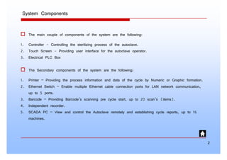
- 1. System Components System Components † Th i l f t f th t th f ll i † The main couple of components of the system are the following: 1. Controller - Controlling the sterilizing process of the autoclave. 2. Touch Screen - Providing user interface for the autoclave operator. 3. Electrical PLC Box † The Secondary components of the system are the following: 1. Printer – Providing the process information and data of the cycle by Numeric or Graphic formation. 2. Ethernet Switch – Enable multiple Ethernet cable connection ports for LAN network communication, up to 5 ports. up to 5 ports. 3. Barcode – Providing Barcode’s scanning pre cycle start, up to 20 scan’s (items). 4. Independent recorder. 5. SCADA PC – View and control the Autoclave remotely and establishing cycle reports, up to 16 y g y p , p machines. 2
- 2. System Capabilities System Capabilities 1. Enhance PLC - Allen Bradley, MicroLogix1400. 2 T h I f 5 6” 7” d 10” 2. Touch screen Interface 5.6”, 7” and 10”. 3. Communications available on board: ƒ LAN 10/100 Mbps EtherNet/IP ƒ 2 Serial RS 232 ports ƒ 2 Serial RS-232 ports. 4. Printer connected for online data processing in serial comm. ƒ Thermal printer (Seiko DPU30, DPU414 graphic) ƒ Dot Impact printer (Citizen CBM920 IDP3550 2 color) Dot Impact printer (Citizen CBM920, IDP3550 2 color). 5. External flash memory for backup the program code for controller. 6. Supporting Multilanguage 7. Auto Sleep and Start mode options. 7. Auto Sleep and Start mode options. 8. Calibrating the Analog sensors 9. Up to 22 programs available. ƒ 11 factory validated programs (Wrapped, Unwrapped, Liquids…). y g ƒ 7 custom setting programs (Generic 1-7). ƒ 2 test programs (B&D test, Leak test). 3
- 3. 10. Flexibility and large program parameters setting per cycle. ƒ U 2 f l d ƒ Up to 2 sets of pulses – pre-vacuum and post-vacuum. ƒ Up to 2 sets of temperature staying during heating. ƒ Heat step – Rating the steam pressure pre sterilization. ƒ Setting the operation rate on Vacuum Cooling and Exhaust ƒ Setting the operation rate on Vacuum, Cooling and Exhaust. ƒ Dry air on/off. ƒ Enable/Disable a program. ƒ F0 Temp F0 Temp. ƒ Selecting the units display: [°F <-> °C] , [kPa <-> PSI/iHg]. ƒ Printing rates. ƒ Screen saver time. Screen saver time. 11. Barcode (optional)- up to 20 scans. 12. Supporting up to 11 users with up to 5 different levels. 13. Supporting historical Data/Events viewer – up to 2 days. g y 14. Backup cycles data on external memory card (optional). 15. Trends display and technician In/Out test. 4
- 4. Field Wiring Touch Screen Printer RS232 Main Controller Touch Screen PLC – ML1400 RTD AI DO Ethernet RS232 SW Barcode Reader Printer Controller PLC – ML1100 Independent Recorder PC / SCADA Printer 5 Figure 3 – Communication & Wiring
- 5. Left Side Panel Front door 380 mm PS 12 VDC Line Feed From Surge Suppressor 1 1 L1 3 L3 5 L5 10 1 L1 3 L3 13 NO 5 L5 A1 8 L L 9 9 600 mm Field TB1 FAN G N 7 24VDC Power Supply G N TB10 1 0 12 Main Switch 0 2 T2 4 T4 6 T6 PKZM 2 T2 4 T4 6 T6 14 NO A2 DILM 11 L3 L1 L2 8 N G PLC CB T Field CB2 C4 T PLC CB1 C2 25 +24V Field I/O +24V Panels 1 2 -24V (B32) -24V -24V 0e (B11) 0s (B12) 0r (B13) 1e (B14) 0 (B23) 1 (B24) 0(B1) / 1(B2) 2(B3) / 3(B4) 4(B5) / 5(B6) 6(B7) / 7(B8) +24VDC +24VDC (B30) DI AI RTD 8(B9) / 9(B10) 0(A1) / 1(A2) 2(A3) / 3(A4) 0(A11) / 1(A12) 2(A13) / 3(A14) 4(A15) / 5(A16) 6(A17) / 7(A18) 8(A19) / 9(A20) 10(A21) / 11(A22) 12(A23) / 13(A24) 14(A25) / 15(A26) +24VDC DO 1s (B15) 1r (B16) 2e (B17) 2s (B18) 2r (B19) 2 (B25) 3 (B26) +24VDC 3e (B20) 3s (B21) 3r (B22) 0 (B27) 1 (B28) +24VDC (B31) 4(A5) / 5(A6) 6(A7) / 7(A8) 8(A9) / 9(A10) 2 3 (B29) Back door 380 mm Surge Suppresor DO RTD AI TB2 TB4 TB8 TB7 TB5 Slot 0 Slot 1 Slot 0 TB6 Slot 2 Slot 3 TB9 Slot 0 600 mm TB11 DO (Slot 1) RTD (Slot 2) 2 3 4-20mA (Slot 3) 4 B A PLC (Slot 0) 1 Connector 2 x 32 PIN Male Female Switch 10/100 6 200 mm
- 6. 7
- 7. 8
- 8. 9
- 9. 10
- 10. Controller Overview † Th C t ll d l i th ft th t th P bl L i C t ll (PLC) Controller Overview † The Controller module is the software program that runs the Programmable Logic Controller (PLC) during the autoclave operation. This software module was programmed with the “RSLogix 500” software application, which was produced and supplied by the manufacturer of the controller hardware “Rockwell Automation Technologies Inc ” (http://www ab com/) hardware, Rockwell Automation Technologies Inc. (http://www.ab.com/). Specification for AB ML1400 1766 1766- -L L32 32BWAA BWAA : Specification for AB ML1400 1766 1766 L L32 32BWAA BWAA : 1. 20 Digital Inputs (24V DC) 2. 4 Analog Inputs (0-10V DC) 3. 12 Digital Outputs (AC/DC relay) 4. 2 Analog Outputs (0-10V DC) 5. Ethernet, RS-232/RS-485 ports C 6. LCD display keypad 7. Up to 7 expansion I/O modules 11
- 11. 1. Comm port 2 - 9-pin D-Shell RS-232C connector 2. Memory module 3. User 24V 3. User 24V 4. Input terminal block 5. LCD Display Keypad 6. Battery compartment 7. 1762 expansion bus connector 8. Battery connector 9. Output terminal block 10. LCD Screen 11. Controller status 12. Comm port 1 – Ethernet RJ45 connector 13. Comm port 0 - 8-pin mini DIN RS-232C/RS-485 connector 12 12
- 12. Th i I/O d l i tt h d t th t ll th I/O The expansion I/O module is attached to the controller or another I/O module by means of a flat ribbon cable after mounting, as shown below. The expansion modules: 1. Digital Outputs - 1762-OW1 16 channels AC/DC relay 2. Analog Inputs - 1762-IR4 / 4 channels RTD/Resistance 3. Analog Inputs – 1762-IF4 4 channels Voltage/Current 13
- 13. Touch Screen Overview † Th T h S U I t f d l i th ft th t id M i M hi I t f Touch Screen Overview † The Touch Screen User Interface module is the software that provides a Main-Machine Interface (MMI) to the touch screen for operating the sterilizing machine. This software module was programmed with the “Easy Builder 8000” software application, which was produced and supplied by the manufacturer of the touch screen hardware “Weintek Labs Inc ” by the manufacturer of the touch screen hardware, Weintek Labs Inc. (http://www.weintek.com/). Specification for Weintek MT8070iH: Specification for Weintek MT8070iH: 1. 7” 800x480 TFT LCD 2. LED Back Light 3. Built-in flash memory and RTC 4. Power Isolator inside 5. SD Card slot S / S / 6. Ethernet, RS-232/RS-485 2w/4w ports 7. USB 1.1 host and USB 2.0 client 14
- 14. 15
- 15. a. DIP SW & Reset button b. Fuse c. Power connector c. Power connector d. VESA 75mm screw holes e. Audio f. SD card slot g. Com1 RS485, Com3 RS485, Com3 RS232 h. Com1 RS232, Com2 RS232 i. Ethernet port (RJ-45) j. USB Host port k. USB Client port 16 16
- 17. 18
- 18. 19
- 19. 20
- 20. OV1 0 TB4 FU 2A JB Connector Connector B B31 B31 IV2 IV0 IN19 TB5 N 18 com ANA IV1 IV3 OUT 10 OUT 8 com ANA OUT 11 OUT 9 V AC DC6 OV 0 IV2 Drain 0 1 JB Connector A B27 B27 B28 B28 - + TIT-001 500Ω 8 2 1 SV-099 A9 A9 9 2 1 SV-018 A10 A10 Air Detect Water Air Detect Steam 2 3 B29 B29 Air Detect 500Ω 500Ω 500Ω - + PIT-001 - + TIT-002 Filter IN17 IN15 IN13 o m 3 I N IN16 IN14 IN12 OUT 4 O UT 3 OUT 7 VAC DC5 VAC DC4 OUT 5 V OUT 6 Vacuum Fast Exhaust 3 4 5 Slow Exhaust 2 1 SV-073 2 1 SV-075 A4 A5 A6 A4 A5 A6 6 2 1 SV-072 A7 A7 2 1 SV-074 Filter Drain 7 2 1 SV-012 A8 A8 Water to Ejector Outputs IN10 IN8 IN7 c o 3 N6 com 2 IN9 IN11 OUT 0 O OUT 2 OUT 1 V AC D C0 VAC DC1 VAC DC2 VAC DC3 Emergency Stop Door 2 Open 7 6 8 9 Steam to Chamber Vacuum Pump/Ejector Steam to Jacket 0 1 2 B7 B8 B9 B10 LS-006 2 1 SV-015 2 1 SV-091 2 1 SV-093 A1 A2 A3 A1 A2 A3 B7 B8 B9 B10 PD-001 A30 LSL-002 A30 XR-001 K -24V LS-001 LS-004 PD-002 Foot Pedal 1 Foot Pedal 2 50 51 ES-001 ES-002 com 1 IN2 0 IN5 FU 2A IN1 IN3 IN4 I N VAC L2/N VAC L1 V D Door 1 Close Door 1 Open Door 2 Close 0 1 2 3 4 5 B1 B2 B3 B4 B5 B6 LS-004 LS-003 LS 001 B1 B2 B3 B4 B5 B6 A28 A28 (-) SI 1 Air Supply Water Supply Steam Supply PS-004 PS-003 PS-005 PLC (Slot 0) IN 0 FU 2A com 0 24V (+) 24V (-) DC OUT Door 1 Close +24V 0 B1 (-) LS-001 B1 21
- 21. 22
- 22. 23
- 23. Door 1 Close Door 1 Lock Seal A12 A14 TB6 SV-039-1 SV-034-1 Buzzer Door 1 Open A13 SV-038-1 SV-053-1 Out 0 Out 2 VDC1 Out 1 Out 3 TB6 0 2 A13 Connector A AB Buzzer 1 3 A2 A14 Connector A AB 2 BZ-002 BZ-001 A11 A11 SI 2 2 SI 3 (1) 3 Pres. Sw Gasket 1 2 1 1 2 18 A45 A40 SI 3 (1) 15 16 A47 A43 PS-001 Door 2 Open A16 Door 1 Unlock Unseal A15 SV-053-1 Door 2 Close A17 SV-039-2 Door 2 Lock Seal A18 SV-034-2 Out 4 Out 6 Out 7 Out 3 Out 5 SV-038-2 DO 4 6 7 A15 A17 A18 5 A16 1 2 1 2 1 2 1 2 1 SI 3 (2) 3 SI 2 2 Pres. Sw Gasket 2 16 15 SI 3 (1) SI 3 (2) 18 SI 3 (2) A46 A40 A48 A44 PS-002 Door 2 Unlock Unseal A19 SV-053-2 A21 VDC2 Out 8 Out 10 Out 9 A20 (Slot 1) 8 10 A19 A21 9 A20 2 1 SI 2 2 1 2 SV-043 Atmospheric Air A40 Cool Water / Drain Jacket SV-011/068 1 LVS-003 A?? A22 A24 A26 A23 Drain A25 SV-012 Out 10 Out 12 Out 14 Out 11 Out 13 Out 15 12 14 A23 A25 (-) 11 13 15 A22 A24 A26 ( ) 2 1 Main Exhaust 1 2 SV-070 1 2 SV-076/096 Bio Vacuum SV-098/066 2 1 Cooling Vacuum Bio Filter 1 2 SV-031 2 TB6 (-) FU 5A TB5 24
- 24. 25
- 25. 26
- 26. Eliwell 10 11 12 7 6 1 2 3 IC912 Supply AC/DC Pt100 Sensor Out 27
- 27. Chamber Water Level GICAR A32 Water Level Relay A32 RT112 Sm 1 2 GICAR DRLH Electrode high L N SM R GICAR DRLH Electrode high (water ) Electrode Reference VAC 28
- 28. 29
- 30. L1 N Safety Interlock 1 (SI 1) G Feed from Main Switch See drawing - ES1P03-0002-0002 TB10 Surge Suppressor PIT-005 Recorder PLC CB1 L N L T CB2 L T B32 JB A27 A28 Connector A A27 A28 B8 (-) B8 GICAR L N 2A ES1 ES2 Pt100 condense Red Red Yellow Pressure chamber From JB (B30) +24VDC R=250Ω Start/Stop Relay (CR3) TI-002 NO From (B32) -24VDC 1 Safety Interlock 2 (SI 2) RT112 IN7 TB4 +24V 2 2 TB2 TB5 PLC Box TB2 A40 (-) JB JB (A32) Connector A32 DRLH L N GICAR 10 11 12 7 6 1 2 3 Eliwell IC912 Eliwell 1 2 1 2 Eliwell L N Power Supply 5/12 VDC L N 4A Recorder FUJI 13 12 11 31 32 11 21 ~ VAC -24V TB2 - + Power Supply 24 VDC L N Chamber Water Level Relay GICAR A32 RT112 + - Supply AC/DC Pt100 Sensor Out Safety Interlock 3 (SI 3) AB 2 3 c c n.c. n.c. n.o. n.o. n.o. 5 C Printer + - Electrode high (water ) Sm L N SM R 1 2 GICAR DRLH (-) From PLC Close Door Output (+24V) 15 16 18 A2 A1 AB 1 2 3 2 1 B1 2 1 Open Door 1 c n.c. Off Delay Relay E, 2min A13 (A16) Red Black White A12 (A17) A43 A41 (A42) A47 TB2 SI1 A28 JB A27 (-) JB A32 Connector A Panel View 1 + - A27 Connector A Panel View 2 + - Electrode Reference VAC Use SI 3 for Automatic sliding doors only. Door Switch 3 2 (-) Close Door A43 (A44) A47 (A48) Control Electrical Panel Cascade Diagram ES1P05-0001 31
- 31. PIT-005 Pt100 Pressure chamber TI-002 condense +24VDC V DC d d llow o m JB (B30) + R=250Ω Start/Stop Relay (CR3) NO om (B32) -24 V 13 12 11 31 32 11 21 Re Re Ye Fr o Fr o Recorder FUJI ~ VAC 32
- 32. IP Address Setting IP Address Setting <OK> <OK> <OK> <OK> See IP status Set IP Address <OK> <OK> <OK> <OK> <OK> <ESC> 33
- 33. Memory Module Load from MM Memory Module – Load from MM <OK> <OK> <OK> <OK> <OK> <OK> <OK> <ESC> 34
- 34. Memory Module Store to MM Memory Module – Store to MM <OK> <OK> <OK> <OK> <OK> <OK> <ESC> 35
- 35. LCD Setup Back Light LCD Setup – Back Light <OK> <OK> <OK> <OK> <ESC> 36
- 36. System Setting Bar System Setting Bar 37
- 37. System Setting System Setting Setting Bar Network Security 38
- 38. More System Setting More System Setting Time/Date History Firmware Setting Flash Memory Card VNC Server 39
- 39. Download Project to Panel via USB Device Download Project to Panel via USB Device Extract Save Plug in File name Zip file USB Device Touch Screen + usbdisk + device-0 +………… +………… + File name +………… + +………… Highlight only No sub selection 40
- 40. 41