Download to read offline
![International Research Journal of Engineering and Technology (IRJET) e-ISSN: 2395 -0056
Volume: 04 Issue: 03 | Mar -2017 www.irjet.net p-ISSN: 2395-0072
© 2017, IRJET | Impact Factor value: 5.181 | ISO 9001:2008 Certified Journal | Page 1662
SMART HELMET USING GSM AND GPS
Aditi Varade1, Neha Gajbhiye2, Mousam3, Assistant. Prof. V.V.Panchbhai4
1Student, Dept. of Electronics and Telecommunication Engineering, Priyadarshini College of Engineering, Nagpur
2Student, Dept. of Electronics and Telecommunication Engineering, Priyadarshini College of Engineering, Nagpur
3Student, Dept. of Electronics and Telecommunication Engineering, Priyadarshini College of Engineering, Nagpur
4 Assistant Professor, Dept. of Electronics and Telecommunication Engineering, Priyadarshini College of
Engineering, Nagpur, Maharashtra, India
---------------------------------------------------------------------***---------------------------------------------------------------------
Abstract - Everyday around theworldalargepercentageof
people die from road accident. An effective approach is made
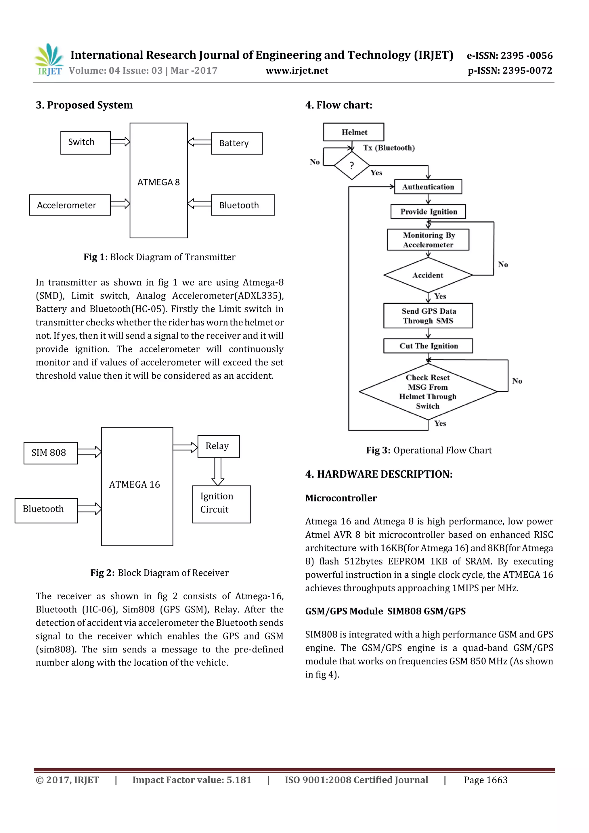
to solve the problem by using smart helmet band. Smart
helmet band is an idea which make motorcycle driving safer
than before. The working of this smart helmet band is very
simple, Limit switch is placed inside the helmet, which will
detect whether the rider has worn the helmet or not, if not
then the bike will not start. Smart helmet band provides help
in case of accident by using GSM and GPS technology.
Key Words: SIM808(GSM, GPS), Limit Switch, Bluetooth,
Accelerometer,MicrocontrollerATMEGA16,Microcontroller
ATMEGA8(SMD).
1. Introduction
Now a day bikers in our country are increasing and road
mishaps are also increasing day by day. Many casualties
occur due to the negligence of wearing helmet. The project
makes compulsory to wear the helmet, if the person met
with an accident then in such situation a message alongwith
the location is sent to the ambulance or family member to
rescue him. The project aims at intelligence security band
providing awareness for wearing helmet and also provides
prevention for human life safety.
2. Related Work
Many authors presented their work regarding safety against
road accident. Some of them are described below:
Accident prevention and Reporting System Using
GSM(sim900D) and GPS(NMEA 0183),has been described in
[1].The presented system includes SONAR ranging modules,
vibration sensor, three modules GPS receiver(NMEA),
Microcontroller(AT89S51),GSMmodem(SIM900D)ANDAN
Alarm. It enables intelligent detection of an accident at any
place and reports about the accident on predefined number.
When the distance is too short between the vehicle and
obstacle then alarm will be “ON” as an indicator to move
vehicle in other direction which is safer but when a vehicle
faces accident despite of alarm, immediate vibration sensor
will detect the signal and Microcontroller sends the alert
message through the GSM model includingthelocationtothe
predefined number. This provides an automatic accident
prevention and reporting system.
The research paper [2] aims at finding the occurrence of any
accident and reporting the location of accident to the
previously coded numbers so that immediate help can be
provided by ambulance or the relative concerned. GSM
technology is used to intimatethevehiclepositionintheform
of latitude and longitude coordinates through sms. The
location spot is retrieved using GPS which is navigational
system using a networkofsatelliteorbitingtheearth.Sensors
such as vibration, alcohol and fire detectors detect signal in
case of an accident occurrence and send a signal to the
connected microcontroller. The controller in turn operates
the relay to glow the airbag and automatically lock the
brakes. This paper gives a design which have many benefits
like low cost, small size.
Real TimeVehicleDetectionandTrackingUsingGPSandGSM
[3]. This paper presents review on the accident detection
techniques and some future possibilities in this field. The
purpose of the project is to find the vehicle and locate the
vehicle by means of sending a message using a system which
is placed inside a vehicle. The project is designed for vehicle
accident detection and tracking system by using GSM and
GPS.](https://image.slidesharecdn.com/irjet-v4i3383-171228091937/75/Smart-Helmet-using-GSM-and-GPS-1-2048.jpg)
![International Research Journal of Engineering and Technology (IRJET) e-ISSN: 2395 -0056
Volume: 04 Issue: 03 | Mar -2017 www.irjet.net p-ISSN: 2395-0072
© 2017, IRJET | Impact Factor value: 5.181 | ISO 9001:2008 Certified Journal | Page 1667
6. CONCLUSIONS
In this project we have successfullydesigneda smarthelmet
band using GSM and GPS technology. The project made
compulsory of wear helmet to start the ignition of vehicle
and while riding if any sudden changeinvelocity occursthen
accelerometer will monitor the change and a short message
with the location of rider will be send to the predefined
number using GSM module. This is a situation where we
found some solution to the problem of increaseddeath ratio.
REFERENCES
[1] R.Nazir, A.Tariq, S.Murawwat, S.Rabbani “Accident
Prevention and Reporting System Using GSM (SIM
900D) and GPS (NMEA 0183)” Dept. of Electrical
Engineering, Lahore College for Women University,
Lahore, Pakistan, Accepted 30 July 2014.
[2] D.Kumar, S.Gupta, S.Kumar, S.Srivastava “Accident
Detection and Reporting System Using GPS and GSM
Module” Dept. of Electronics and Instrumentation
Engineering, Galgotias College of Engineering and
Technology, Greater Noida,India, Volume2,Issue5,May
2015.
[3] N.sane, D.Patil, S.Thakare, A.Rokade “Real Time Vehicle
Accident Detection and Tracking Using GPS and GSM”
International Journal on Recent and Innovation Trends
in Computing and Communication, Volume 4, Issue 4,
April 2016.
[4] C.Prabha, R.Sunita, R.Anita “Automatic Vehicle Accident
Detection and Messaging System Using GSM and GPS
Modem”,Assistant professor, Dept. of ECE, Bellari
Institute of Technology and Management, Bellary,
Karnataka, Volume 3,Issue 7, July 2014.
[5] Manjesh N, Prof . Sudarshan Raj “Smart Helmet Using
GSM and GPS Technology for Accident Detection and
Reporting System” , M tech , ECE –DSCE ,JNTUA
Hindupur, HOD and Ass. Prof. BIT-IT, Hindupur, India,
Volume 2, Issue 4, pp:(122-127), Oct –Dec 2014.
[6] Jennifer William, Kaustubh Padwal , Nexon Samuel,
Akshay Bawkar, Smita Rukhande,”Intelligent
Helmet”,International Journal of Scientific and
Engineering Research,Volume 2,Issue 3,March 2016.
BIOGRAPHIES
Aditi Varade, B.E final year
student, Dept. of Electronics
and Telecommunication
Engineering, Priyadarshini
College of Engineering,
Nagpur.
Neha Gajbhiye, B.E final year
student, Dept. of Electronics
and Telecommunication
Engineering, Priyadarshini
College of Engineering,
Nagpur.
Mousam, B.E final year
student, Dept. of Electronics
and Telecommunication
Engineering, Priyadarshini
College of Engineering,
Nagpur.
Mr.V.V.Panchbhai, Assistant
Professor, Dept. of Electronics
and Telecommunication
Engineering, Priyadarshini
College of Engineering,
Nagpur He is having 10 years
of teaching experience. He
has more than 6 papers in
National / International
journals to his credit.](https://image.slidesharecdn.com/irjet-v4i3383-171228091937/75/Smart-Helmet-using-GSM-and-GPS-6-2048.jpg)

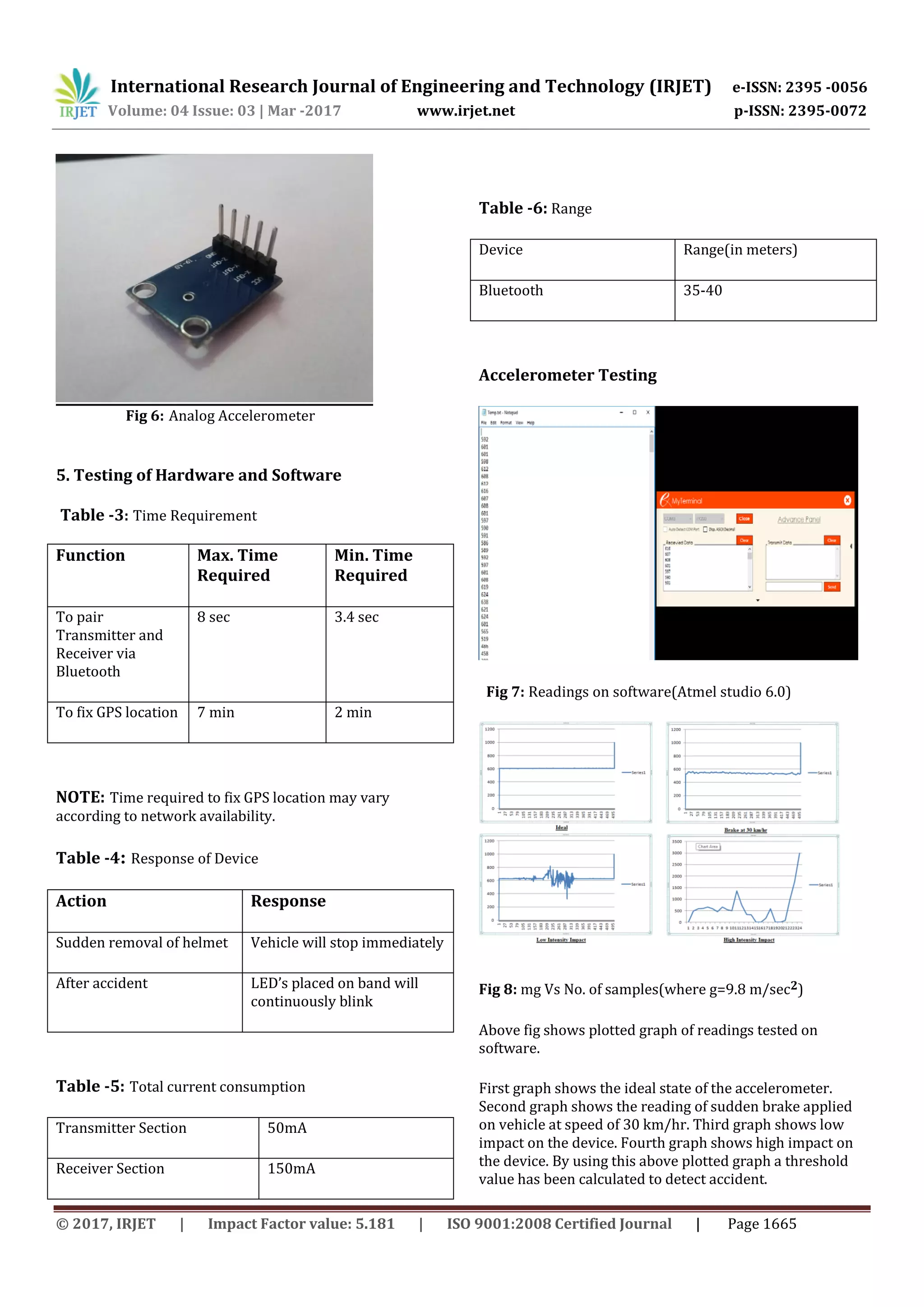
1. The document describes a smart helmet system that uses GSM and GPS technology to improve motorcycle safety. 2. The system includes an accelerometer in the helmet that detects accidents. If an accident is detected, the system sends an alert message with the rider's location via GSM to predefined emergency contacts. 3. The system also includes a limit switch that prevents the motorcycle from starting if the rider is not wearing the helmet, enforcing the use of safety gear.