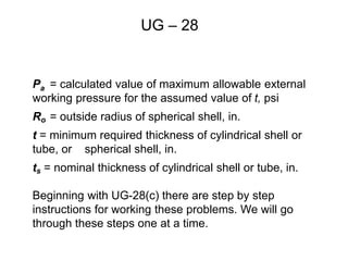
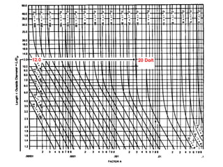
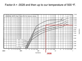
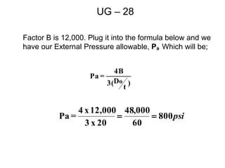
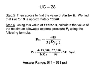
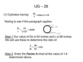
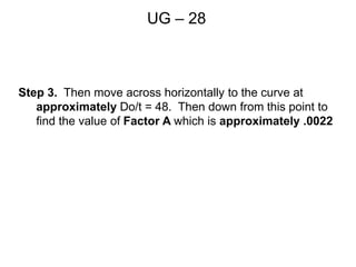
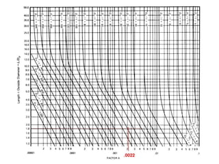
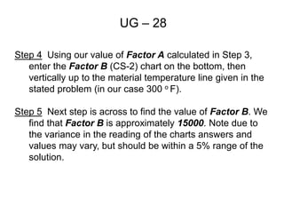
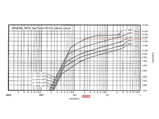
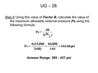
API Preparatory Class
Lesson 7
External Pressure Calculations
(a) Rules for the design of shells and tubes under external
pressure given in this Division are limited to cylindrical
shells, with or without stiffening rings, tubes, and
spherical shells…..
(b) The symbols defined below are used in the procedures
of this paragraph:
A = factor determined from Fig. G in Subpart 3 of Section
II, Part D and used to enter the applicable material chart
in Subpart 3 of Section II, Part D……
B = factor determined from the applicable material chart
in Subpart 3 of Section II, Part D for maximum design
metal temperature, psi .
UG – 28 Thickness of Shells and Tubes
Under External Pressure
Page 24 Section VIII
Do = outside diameter of cylindrical shell course or tube,
in.
E = Not on exam.
L = total length, in. (mm), of a tube between tubesheets,
or design length of a vessel section between lines of
support (see Fig. UG-28.1). A line of support is:
(1) a circumferential line on a head…. Not on exam!
(2) a stiffening ring……. Not on exam!
(3) a jacket closure ……. Not on exam!
(4) a cone-to-cylinder Not on exam!
P = external design pressure, psi
UG – 28
Pa = calculated value of maximum allowable external
working pressure for the assumed value of t, psi
Ro = outside radius of spherical shell, in.
t = minimum required thickness of cylindrical shell or
tube, or spherical shell, in.
ts = nominal thickness of cylindrical shell or tube, in.
Beginning with UG-28(c) there are step by step
instructions for working these problems. We will go
through these steps one at a time.
UG – 28
(c) Cylindrical Shells and Tubes. The required minimum
thickness of a cylindrical shell or tube under external
pressure, either seamless or with longitudinal butt joints,
shall be…….
1. Cylinders having Do /t values > or = 10:
Step 1 Assume a value for t and determine the ratios
L/Do and Do /t.
* You do not assume a value for thickness (t) on the exam, it
will be given in the stated problem for the external pressure
shell or tube calculation. As will the (Do) Diameter Outside
and the (L) Length in other words all that is needed to solve
the problem will be provided.
Looking at an example, we can start learning this process.
UG – 28
1. Cylinders having Do /t values > or = 10:
Step 1 Assume a value for t and determine the ratios
L/Do and Do /t.
Example: The cylinder has corroded to a wall thickness of
0.530”, its length is 120” and the outside diameter is 10”. It
operates at 500 oF
So then;
Temperature = 500 oF
t = 0.530”
L = 120”
Do = 10”
Calculate Do/t = 10/.530 = 18.8 call it 19 (no need to be exact)
Now we do L/Do = 120/10 = 12
UG – 28
Step 2 Enter Fig. G in Subpart 3 of Section II, Part at the
value of L/Do determined in Step 1. For values of L/Do
greater than 50, enter the chart at a value of L/Do = 50.
For values of L/Do less than 0.05, enter the chart at a
value of L/Do = 0.05.
In our example problem we must go up the left side of
the Fig. G until we reach the value of L/Do of 12.
• Using the chart we have the following;
UG – 28
Step 3 Move horizontally to the line for the value Do /t
determined in Step 1.... Which in our case was 19, but
we will round this to 20 since these problems are not
meant to be extremely precise. So now we have.
UG – 28
Step 3. Continued.
From this point of intersection move vertically downward to
determine the value of factor A.
Which gives us the following;
UG – 28
Step 4
Using the value of A calculated in Step 3, enter the
applicable material chart in Subpart 3 of Section II, Part D
for the material under consideration. Move vertically to an
intersection with the material/temperature line for the design
temperature see UG-20). Interpolation may be made
between lines for intermediate temperatures. In cases
where the value of A falls to the right of the end of the
material /temperature line, assume an intersection with the
horizontal projection of the upper end of the
material/temperature line.
To use the next figure we enter at the bottom at the value
Factor A = .0028 and then up to our temperature of 500 oF.
UG – 28
Factor A = .0028 and then up to our temperature of 500 oF.
Factor B is 12,000. Plug it into the formula below and we
have our External Pressure allowable, Pa Which will be;
UG – 28
)
t
D
3(
4B
=
Pa
o
psi
800
60
000
,
48
20
x
3
12,000
x
4
=
Pa 

All that work just to find Factor B is and plug it into the
simple formula below.
UG – 28
)
t
D
3(
4B
=
Pa
o
As regards the final answers to these problems, because of
the difficulty of being precise with the Fig. G there will always
be some difference from one person to the next in the
determination of Factor A. This is allowed for on the exam by
listing choices of answers that are in a range of +/- 5%. In our
previous problem the answer was 800 psi, on the exam the
correct choice would have been offered as 760 to 840 psi, i.e.
Answer Range: 760 – 840 psi
To Summarize UG-28
External calculations depart significantly from internal
calculations simply because under external pressure the
vessel is being crushed. Internal pressure wants to tear the
vessel apart.
Because of the crushing or buckling load, the Length the
Outside Diameter and the Thickness of the vessel are
important. External pressure problems are based on the
thickness of the shell to the outside diameter ratios. There
are two types of external pressure calculations, the type we
will use is when the O.D to (Do) thickness ratio (t) is greater
than 10 and the other type, not on the test, is when it is less
than 10.
To Summarize UG-28
In order to solve these types of problems two charts will be
required. The first chart Fig. G is used to find a value called
Factor A and then Factor A is used to find a Factor B in the
second material specific chart. The value of Factor B found
is the number needed to solve the problem using the
formula given in paragraph UG-28 (c)(1) step 6. As stated in
the API 510 Body of Knowledge, these charts will be
provided in the exam body, IF an external calculation is
given on the examination.
One more problem. Find the allowed external pressure on
an existing vessel of a known thickness with a Do/t ratio >
10.
UG-28
Problem: A vessel is operating under an external pressure,
the operating temperature is 500° F. The outside diameter of
the vessel is 40 inches. Its length is 70 inches. The vessel’s
wall is 1.25 inches thick and is of SA-515-70 plate. Its
specified min. yield is 38,000 psi. What is the maximum
external pressure allowed?
Givens:
Temp = 500° F
t = 1.25
L = 70 inches
D0 = 40 inches
UG – 28
From UG-28 (c)Cylindrical Shells and Tubes. The
required minimum thickness of a shell or a tube under
external pressure, either seamless or with longitudinal
butt joints, shall be determined by the following
procedure.
(1) Cylinders having a
Testing to see if this paragraph applies:
10
values
t
Do
³
UG – 28
Step 1 Our value of Do is 40 inches and L is 70 inches. We
will use these to determine the ratio of:
32
=
1.25
40
=
t
Do
1.75
=
40
70
=
o
D
L
Step 2 Enter the Factor A chart at the value of 1.75
determined above.
Step 3 Then move across horizontally to the curve Do/t =
32. Then down from this point to find the value of Factor A
which is .0045
UG – 28
Step 4. Using our value of Factor A calculated in Step 3,
enter the Factor B (CS-2) chart on the bottom. Then
vertically to the material temperature line given in the stated
problem (in our case 500 o F).
UG – 28
Step 5 Then across to find the value of Factor B. We find
that Factor B is approximately 13000.
Step 6 Using this value of Factor B, calculate the value of
the maximum allowable external pressure Pa using the
following formula:
)
t
D
3(
4B
=
Pa
o
psi
541.66
=
96
52,000
=
3(32)
4x13,000
=
Pa
Answer Range: 514 – 568 psi
Class Quiz
UG-28
A vessel under external pressure has been found to a
thickness of 1.123 ". The vessel is 8'-2" long and operates at
a temperature of 300 oF. The vessel’s outside diameter is 54
inches. It is made of a material with a minimum yield of
30,000 psi. Presently the external working pressure is 350
psi. May this vessel continue to operate in accordance with
the Code? Show all work and quote code paragraphs used.
(1) Cylinders having:
UG – 28
10
values
t
Do
³
Testing to see if this paragraph applies:
48.08
=
1.123
54
=
t
Do
Step 1 Our value of Do is 54 inches and L is 98 inches.
We will use these to determine the ratio of:
1.81
=
54
98
=
o
D
L
Step 2 Enter the Factor A chart at the value of 1.8
determined above.
UG – 28
Step 3. Then move across horizontally to the curve at
approximately Do/t = 48. Then down from this point to
find the value of Factor A which is approximately .0022
Step 4 Using our value of Factor A calculated in Step 3,
enter the Factor B (CS-2) chart on the bottom, then
vertically up to the material temperature line given in the
stated problem (in our case 300 o F).
Step 5 Next step is across to find the value of Factor B. We
find that Factor B is approximately 15000. Note due to
the variance in the reading of the charts answers and
values may vary, but should be within a 5% range of the
solution.
UG – 28
Step 6 Using this value of Factor B, calculate the value of
the maximum allowable external pressure Pa using the
following formula:
UG – 28
)
t
D
3(
4B
=
Pa
o
psi
416.66
=
144
60,000
=
3(48)
4x15,000
=
Pa
Answer Range: 395 - 437 psi
Later….

EXTERNAL PRESSURE CALC.ppt

  • 1.
    API Preparatory Class Lesson7 External Pressure Calculations
  • 2.
    (a) Rules forthe design of shells and tubes under external pressure given in this Division are limited to cylindrical shells, with or without stiffening rings, tubes, and spherical shells….. (b) The symbols defined below are used in the procedures of this paragraph: A = factor determined from Fig. G in Subpart 3 of Section II, Part D and used to enter the applicable material chart in Subpart 3 of Section II, Part D…… B = factor determined from the applicable material chart in Subpart 3 of Section II, Part D for maximum design metal temperature, psi . UG – 28 Thickness of Shells and Tubes Under External Pressure Page 24 Section VIII
  • 3.
    Do = outsidediameter of cylindrical shell course or tube, in. E = Not on exam. L = total length, in. (mm), of a tube between tubesheets, or design length of a vessel section between lines of support (see Fig. UG-28.1). A line of support is: (1) a circumferential line on a head…. Not on exam! (2) a stiffening ring……. Not on exam! (3) a jacket closure ……. Not on exam! (4) a cone-to-cylinder Not on exam! P = external design pressure, psi UG – 28
  • 4.
    Pa = calculatedvalue of maximum allowable external working pressure for the assumed value of t, psi Ro = outside radius of spherical shell, in. t = minimum required thickness of cylindrical shell or tube, or spherical shell, in. ts = nominal thickness of cylindrical shell or tube, in. Beginning with UG-28(c) there are step by step instructions for working these problems. We will go through these steps one at a time. UG – 28
  • 5.
    (c) Cylindrical Shellsand Tubes. The required minimum thickness of a cylindrical shell or tube under external pressure, either seamless or with longitudinal butt joints, shall be……. 1. Cylinders having Do /t values > or = 10: Step 1 Assume a value for t and determine the ratios L/Do and Do /t. * You do not assume a value for thickness (t) on the exam, it will be given in the stated problem for the external pressure shell or tube calculation. As will the (Do) Diameter Outside and the (L) Length in other words all that is needed to solve the problem will be provided. Looking at an example, we can start learning this process. UG – 28
  • 6.
    1. Cylinders havingDo /t values > or = 10: Step 1 Assume a value for t and determine the ratios L/Do and Do /t. Example: The cylinder has corroded to a wall thickness of 0.530”, its length is 120” and the outside diameter is 10”. It operates at 500 oF So then; Temperature = 500 oF t = 0.530” L = 120” Do = 10” Calculate Do/t = 10/.530 = 18.8 call it 19 (no need to be exact) Now we do L/Do = 120/10 = 12 UG – 28
  • 7.
    Step 2 EnterFig. G in Subpart 3 of Section II, Part at the value of L/Do determined in Step 1. For values of L/Do greater than 50, enter the chart at a value of L/Do = 50. For values of L/Do less than 0.05, enter the chart at a value of L/Do = 0.05. In our example problem we must go up the left side of the Fig. G until we reach the value of L/Do of 12. • Using the chart we have the following; UG – 28
  • 9.
    Step 3 Movehorizontally to the line for the value Do /t determined in Step 1.... Which in our case was 19, but we will round this to 20 since these problems are not meant to be extremely precise. So now we have. UG – 28
  • 11.
    Step 3. Continued. Fromthis point of intersection move vertically downward to determine the value of factor A. Which gives us the following; UG – 28
  • 13.
    Step 4 Using thevalue of A calculated in Step 3, enter the applicable material chart in Subpart 3 of Section II, Part D for the material under consideration. Move vertically to an intersection with the material/temperature line for the design temperature see UG-20). Interpolation may be made between lines for intermediate temperatures. In cases where the value of A falls to the right of the end of the material /temperature line, assume an intersection with the horizontal projection of the upper end of the material/temperature line. To use the next figure we enter at the bottom at the value Factor A = .0028 and then up to our temperature of 500 oF. UG – 28
  • 14.
    Factor A =.0028 and then up to our temperature of 500 oF.
  • 15.
    Factor B is12,000. Plug it into the formula below and we have our External Pressure allowable, Pa Which will be; UG – 28 ) t D 3( 4B = Pa o psi 800 60 000 , 48 20 x 3 12,000 x 4 = Pa  
  • 16.
    All that workjust to find Factor B is and plug it into the simple formula below. UG – 28 ) t D 3( 4B = Pa o As regards the final answers to these problems, because of the difficulty of being precise with the Fig. G there will always be some difference from one person to the next in the determination of Factor A. This is allowed for on the exam by listing choices of answers that are in a range of +/- 5%. In our previous problem the answer was 800 psi, on the exam the correct choice would have been offered as 760 to 840 psi, i.e. Answer Range: 760 – 840 psi
  • 17.
    To Summarize UG-28 Externalcalculations depart significantly from internal calculations simply because under external pressure the vessel is being crushed. Internal pressure wants to tear the vessel apart. Because of the crushing or buckling load, the Length the Outside Diameter and the Thickness of the vessel are important. External pressure problems are based on the thickness of the shell to the outside diameter ratios. There are two types of external pressure calculations, the type we will use is when the O.D to (Do) thickness ratio (t) is greater than 10 and the other type, not on the test, is when it is less than 10.
  • 18.
    To Summarize UG-28 Inorder to solve these types of problems two charts will be required. The first chart Fig. G is used to find a value called Factor A and then Factor A is used to find a Factor B in the second material specific chart. The value of Factor B found is the number needed to solve the problem using the formula given in paragraph UG-28 (c)(1) step 6. As stated in the API 510 Body of Knowledge, these charts will be provided in the exam body, IF an external calculation is given on the examination. One more problem. Find the allowed external pressure on an existing vessel of a known thickness with a Do/t ratio > 10.
  • 19.
    UG-28 Problem: A vesselis operating under an external pressure, the operating temperature is 500° F. The outside diameter of the vessel is 40 inches. Its length is 70 inches. The vessel’s wall is 1.25 inches thick and is of SA-515-70 plate. Its specified min. yield is 38,000 psi. What is the maximum external pressure allowed? Givens: Temp = 500° F t = 1.25 L = 70 inches D0 = 40 inches
  • 20.
    UG – 28 FromUG-28 (c)Cylindrical Shells and Tubes. The required minimum thickness of a shell or a tube under external pressure, either seamless or with longitudinal butt joints, shall be determined by the following procedure. (1) Cylinders having a Testing to see if this paragraph applies: 10 values t Do ³
  • 21.
    UG – 28 Step1 Our value of Do is 40 inches and L is 70 inches. We will use these to determine the ratio of: 32 = 1.25 40 = t Do 1.75 = 40 70 = o D L Step 2 Enter the Factor A chart at the value of 1.75 determined above. Step 3 Then move across horizontally to the curve Do/t = 32. Then down from this point to find the value of Factor A which is .0045
  • 23.
    UG – 28 Step4. Using our value of Factor A calculated in Step 3, enter the Factor B (CS-2) chart on the bottom. Then vertically to the material temperature line given in the stated problem (in our case 500 o F).
  • 25.
    UG – 28 Step5 Then across to find the value of Factor B. We find that Factor B is approximately 13000. Step 6 Using this value of Factor B, calculate the value of the maximum allowable external pressure Pa using the following formula: ) t D 3( 4B = Pa o psi 541.66 = 96 52,000 = 3(32) 4x13,000 = Pa Answer Range: 514 – 568 psi
  • 26.
    Class Quiz UG-28 A vesselunder external pressure has been found to a thickness of 1.123 ". The vessel is 8'-2" long and operates at a temperature of 300 oF. The vessel’s outside diameter is 54 inches. It is made of a material with a minimum yield of 30,000 psi. Presently the external working pressure is 350 psi. May this vessel continue to operate in accordance with the Code? Show all work and quote code paragraphs used.
  • 27.
    (1) Cylinders having: UG– 28 10 values t Do ³ Testing to see if this paragraph applies: 48.08 = 1.123 54 = t Do Step 1 Our value of Do is 54 inches and L is 98 inches. We will use these to determine the ratio of: 1.81 = 54 98 = o D L Step 2 Enter the Factor A chart at the value of 1.8 determined above.
  • 28.
    UG – 28 Step3. Then move across horizontally to the curve at approximately Do/t = 48. Then down from this point to find the value of Factor A which is approximately .0022
  • 30.
    Step 4 Usingour value of Factor A calculated in Step 3, enter the Factor B (CS-2) chart on the bottom, then vertically up to the material temperature line given in the stated problem (in our case 300 o F). Step 5 Next step is across to find the value of Factor B. We find that Factor B is approximately 15000. Note due to the variance in the reading of the charts answers and values may vary, but should be within a 5% range of the solution. UG – 28
  • 32.
    Step 6 Usingthis value of Factor B, calculate the value of the maximum allowable external pressure Pa using the following formula: UG – 28 ) t D 3( 4B = Pa o psi 416.66 = 144 60,000 = 3(48) 4x15,000 = Pa Answer Range: 395 - 437 psi
  • 33.