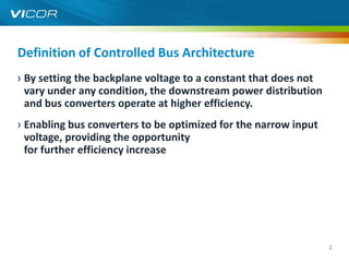
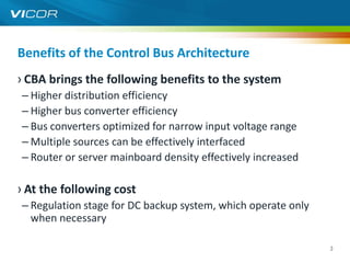
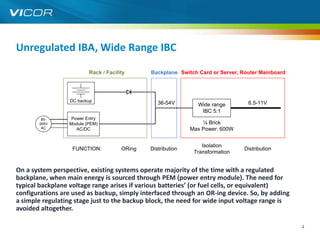
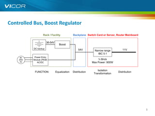
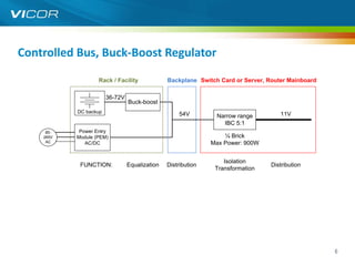
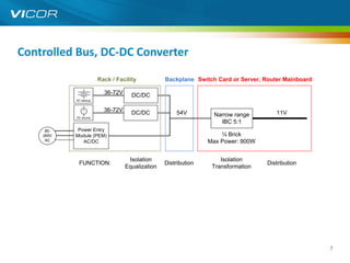
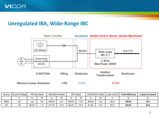
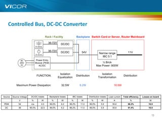
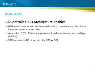
Controlled Bus Architecture


As an alternate to the Intermediate Bus Architecture


                                                       1
Definition of Controlled Bus Architecture
› By setting the backplane voltage to a constant that does not
  vary under any condition, the downstream power distribution
  and bus converters operate at higher efficiency.
› Enabling bus converters to be optimized for the narrow input
  voltage, providing the opportunity
  for further efficiency increase


                                                                 2
Benefits of the Control Bus Architecture
› CBA brings the following benefits to the system
– Higher distribution efficiency
– Higher bus converter efficiency
– Bus converters optimized for narrow input voltage range
– Multiple sources can be effectively interfaced
– Router or server mainboard density effectively increased

› At the following cost
– Regulation stage for DC backup system, which operate only
  when necessary

                                                              3
Unregulated IBA, Wide Range IBC

                         Rack / Facility      Backplane Switch Card or Server, Router Mainboard


                  DC backup
                                                 36-54V        Wide range        6.5-11V
                                                                IBC 5:1
        85-       Power Entry
       265V      Module (PEM)                                    ¼ Brick
        AC          AC/DC                                    Max Power: 600W


                                                                 Isolation
                   FUNCTION:          ORing   Distribution                      Distribution
                                                              Transformation


On a system perspective, existing systems operate majority of the time 43.6Wa regulated
      Maximum power dissipation:      1.4W       13.9W
                                                                            with
backplane, when main energy is sourced through PEM (power entry module). The need for
typical backplane voltage range arises if various batteries’ (or fuel cells, or equivalent)
configurations are used as backup, simply interfaced through an OR-ing device. So, by adding
a simple regulating stage just to the backup block, the need for wide input voltage range is
avoided altogether.

                                                                                                  4
Controlled Bus, Boost Regulator

                        Rack / Facility              Backplane Switch Card or Server, Router Mainboard

                             36-54V
                                         Boost
                 DC backup
                                                         54V          Narrow range          11V
                                                                        IBC 5:1
      85-        Power Entry
     265V       Module (PEM)                                            ¼ Brick
      AC           AC/DC                                            Max Power: 900W


                                                                        Isolation
                  FUNCTION:           Equalization   Distribution                        Distribution
                                                                     Transformation

   Maximum Power Dissipation:           12.6W           6.2W                     16.9W


                                                                                                         5
Controlled Bus, Buck-Boost Regulator

                        Rack / Facility              Backplane Switch Card or Server, Router Mainboard

                             36-72V
                                      Buck-boost
                 DC backup
                                                         54V         Narrow range           11V
                                                                       IBC 5:1
      85-        Power Entry
     265V       Module (PEM)                                            ¼ Brick
      AC           AC/DC                                            Max Power: 900W


                                                                        Isolation
                  FUNCTION:           Equalization   Distribution                        Distribution
                                                                     Transformation

   Maximum Power Dissipation:           15.8W           6.2W                     16.9W


                                                                                                         6
Controlled Bus, DC-DC Converter

                             Rack / Facility           Backplane Switch Card or Server, Router Mainboard

                               36-72V     DC/DC
                 DC backup


                     +
                     -
                               36-72V     DC/DC            54V                                11V
                 DC source
                                                                        Narrow range
                                                                          IBC 5:1
      85-        Power Entry
     265V       Module (PEM)                                              ¼ Brick
      AC           AC/DC                                              Max Power: 900W


                                         Isolation                        Isolation
                  FUNCTION:                            Distribution                        Distribution
                                        Equalization                   Transformation

   Maximum Power Dissipation:             32.5W           6.2W                     16.9W


                                                                                                           7
Test Case


            8
Assumptions this test case

› Load power: 600 W
› Backplane total interconnect resistance: 50 mW
› Intermediate Bus total distribution resistance: 1.9 mW
› OR-ing resistance: 5 mW


                                                           9
Unregulated IBA, Wide-Range IBC

                                            Rack / Facility                Backplane Switch Card or Server, Router Mainboard


                                 DC backup
                                                                              36-54V               Wide range                 6.5-11V
                                                                                                    IBC 5:1
                 85-              Power Entry
                265V             Module (PEM)                                                      ¼ Brick
                 AC                 AC/DC                                                      Max Power: 600W


                                                                                                    Isolation
                                  FUNCTION:                ORing           Distribution                                     Distribution
                                                                                                 Transformation

             Maximum power dissipation:                     1.4W             13.9W                                43.6W


Source   Source Voltage    OR-ing losses        Backplane losses     IBC losses        Distribution losses   Load current   Total efficiency   Losses on board
               V           %          W           %        W        %          W          %         W             A                %                 W
PEM           54           n/a        0.0       99.0%      6.2     98.0%      12.2     99.0%        5.9         55.6            96.0%               18.2
 DC           36          99.8%       1.4       97.7%     13.9     95.2%      30.3     97.8%       13.4         83.3            90.8%               43.6


                                                                                                                                                         10
Controlled Bus, Boost Regulator

                                            Rack / Facility                 Backplane Switch Card or Server, Router Mainboard

                                              36-54V
                                                            Boost
                                 DC backup
                                                                                54V               Narrow range                   11V
                                                                                                    IBC 5:1
                 85-              Power Entry
                265V             Module (PEM)                                                      ¼ Brick
                 AC                 AC/DC                                                      Max Power: 900W


                                                                                                    Isolation
                                  FUNCTION:             Equalization        Distribution                                    Distribution
                                                                                                 Transformation

            Maximum Power Dissipation:                     12.6W               6.2W                               16.9W


Source   Source Voltage    Boost losses         Backplane losses       IBC losses      Distribution losses   Load current   Total efficiency   Losses on board
               V           %          W           %        W         %          W          %        W             A                %                 W
PEM           54           n/a        0.0       99.0%      6.2      98.2%      11.0    99.0%        5.9         55.6            96.2%               16.9
 DC           36          98.0%      12.6       99.0%      6.2      98.2%      11.0    99.0%        5.9         55.6            94.3%               16.9


                                                                                                                                                         11
Controlled Bus, Buck-Boost Regulator

                                            Rack / Facility                Backplane Switch Card or Server, Router Mainboard

                                              36-72V
                                                        Buck-boost
                                 DC backup
                                                                                54V              Narrow range                   11V
                                                                                                   IBC 5:1
                 85-              Power Entry
                265V             Module (PEM)                                                     ¼ Brick
                 AC                 AC/DC                                                     Max Power: 900W


                                                                                                   Isolation
                                  FUNCTION:             Equalization       Distribution                                    Distribution
                                                                                                Transformation

            Maximum Power Dissipation:                     15.8W              6.2W                               16.9W


Source   Source Voltage   Buck-boost losses     Backplane losses       IBC losses     Distribution losses   Load current   Total efficiency   Losses on board
               V            %         W           %        W        %          W          %        W             A                %                 W
PEM           54           n/a        0.0       99.0%      6.2     98.2%      11.0    99.0%        5.9         55.6            96.2%               16.9
 DC           36          97.5%      15.8       99.0%      6.2     98.2%      11.0    99.0%        5.9         55.6            93.8%               16.9


                                                                                                                                                        12
Controlled Bus, DC-DC Converter

                                                Rack / Facility               Backplane Switch Card or Server, Router Mainboard

                                                  36-72V      DC/DC
                                 DC backup


                                     +
                                     -
                                                  36-72V      DC/DC                54V                                             11V
                                 DC source
                                                                                                    Narrow range
                                                                                                      IBC 5:1
                 85-              Power Entry
                265V             Module (PEM)                                                        ¼ Brick
                 AC                 AC/DC                                                        Max Power: 900W


                                                            Isolation                                 Isolation
                                  FUNCTION:                                   Distribution                                    Distribution
                                                           Equalization                            Transformation

            Maximum Power Dissipation:                        32.5W              6.2W                               16.9W


Source   Source Voltage    DC/DC losses            Backplane losses       IBC losses     Distribution losses   Load current   Total efficiency   Losses on board
               V           %             W           %        W        %          W          %        W             A                %                 W
PEM           54           n/a           0.0       99.0%      6.2     98.2%      11.0    99.0%        5.9         55.6            96.2%               16.9
 DC           36          95.0%          32.5      99.0%      6.2     98.2%      11.0    99.0%        5.9         55.6            91.4%               16.9


                                                                                                                                                           13
Conclusions

› A Controlled Bus Architecture enables:
– 61% reduction in worst case intermediate bus conversion and distribution
  losses on server / router board
– As much as 3.5% efficiency improvement under worst case input voltage
  (36 Vdc)
– 50% increase in IBC power density (900 W QB)


                                                                             14

Controlled Bus Architecture (CBA)

  • 1.
    Controlled Bus Architecture Asan alternate to the Intermediate Bus Architecture 1
  • 2.
    Definition of ControlledBus Architecture › By setting the backplane voltage to a constant that does not vary under any condition, the downstream power distribution and bus converters operate at higher efficiency. › Enabling bus converters to be optimized for the narrow input voltage, providing the opportunity for further efficiency increase 2
  • 3.
    Benefits of theControl Bus Architecture › CBA brings the following benefits to the system – Higher distribution efficiency – Higher bus converter efficiency – Bus converters optimized for narrow input voltage range – Multiple sources can be effectively interfaced – Router or server mainboard density effectively increased › At the following cost – Regulation stage for DC backup system, which operate only when necessary 3
  • 4.
    Unregulated IBA, WideRange IBC Rack / Facility Backplane Switch Card or Server, Router Mainboard DC backup 36-54V Wide range 6.5-11V IBC 5:1 85- Power Entry 265V Module (PEM) ¼ Brick AC AC/DC Max Power: 600W Isolation FUNCTION: ORing Distribution Distribution Transformation On a system perspective, existing systems operate majority of the time 43.6Wa regulated Maximum power dissipation: 1.4W 13.9W with backplane, when main energy is sourced through PEM (power entry module). The need for typical backplane voltage range arises if various batteries’ (or fuel cells, or equivalent) configurations are used as backup, simply interfaced through an OR-ing device. So, by adding a simple regulating stage just to the backup block, the need for wide input voltage range is avoided altogether. 4
  • 5.
    Controlled Bus, BoostRegulator Rack / Facility Backplane Switch Card or Server, Router Mainboard 36-54V Boost DC backup 54V Narrow range 11V IBC 5:1 85- Power Entry 265V Module (PEM) ¼ Brick AC AC/DC Max Power: 900W Isolation FUNCTION: Equalization Distribution Distribution Transformation Maximum Power Dissipation: 12.6W 6.2W 16.9W 5
  • 6.
    Controlled Bus, Buck-BoostRegulator Rack / Facility Backplane Switch Card or Server, Router Mainboard 36-72V Buck-boost DC backup 54V Narrow range 11V IBC 5:1 85- Power Entry 265V Module (PEM) ¼ Brick AC AC/DC Max Power: 900W Isolation FUNCTION: Equalization Distribution Distribution Transformation Maximum Power Dissipation: 15.8W 6.2W 16.9W 6
  • 7.
    Controlled Bus, DC-DCConverter Rack / Facility Backplane Switch Card or Server, Router Mainboard 36-72V DC/DC DC backup + - 36-72V DC/DC 54V 11V DC source Narrow range IBC 5:1 85- Power Entry 265V Module (PEM) ¼ Brick AC AC/DC Max Power: 900W Isolation Isolation FUNCTION: Distribution Distribution Equalization Transformation Maximum Power Dissipation: 32.5W 6.2W 16.9W 7
  • 8.
  • 9.
    Assumptions this testcase › Load power: 600 W › Backplane total interconnect resistance: 50 mW › Intermediate Bus total distribution resistance: 1.9 mW › OR-ing resistance: 5 mW 9
  • 10.
    Unregulated IBA, Wide-RangeIBC Rack / Facility Backplane Switch Card or Server, Router Mainboard DC backup 36-54V Wide range 6.5-11V IBC 5:1 85- Power Entry 265V Module (PEM) ¼ Brick AC AC/DC Max Power: 600W Isolation FUNCTION: ORing Distribution Distribution Transformation Maximum power dissipation: 1.4W 13.9W 43.6W Source Source Voltage OR-ing losses Backplane losses IBC losses Distribution losses Load current Total efficiency Losses on board V % W % W % W % W A % W PEM 54 n/a 0.0 99.0% 6.2 98.0% 12.2 99.0% 5.9 55.6 96.0% 18.2 DC 36 99.8% 1.4 97.7% 13.9 95.2% 30.3 97.8% 13.4 83.3 90.8% 43.6 10
  • 11.
    Controlled Bus, BoostRegulator Rack / Facility Backplane Switch Card or Server, Router Mainboard 36-54V Boost DC backup 54V Narrow range 11V IBC 5:1 85- Power Entry 265V Module (PEM) ¼ Brick AC AC/DC Max Power: 900W Isolation FUNCTION: Equalization Distribution Distribution Transformation Maximum Power Dissipation: 12.6W 6.2W 16.9W Source Source Voltage Boost losses Backplane losses IBC losses Distribution losses Load current Total efficiency Losses on board V % W % W % W % W A % W PEM 54 n/a 0.0 99.0% 6.2 98.2% 11.0 99.0% 5.9 55.6 96.2% 16.9 DC 36 98.0% 12.6 99.0% 6.2 98.2% 11.0 99.0% 5.9 55.6 94.3% 16.9 11
  • 12.
    Controlled Bus, Buck-BoostRegulator Rack / Facility Backplane Switch Card or Server, Router Mainboard 36-72V Buck-boost DC backup 54V Narrow range 11V IBC 5:1 85- Power Entry 265V Module (PEM) ¼ Brick AC AC/DC Max Power: 900W Isolation FUNCTION: Equalization Distribution Distribution Transformation Maximum Power Dissipation: 15.8W 6.2W 16.9W Source Source Voltage Buck-boost losses Backplane losses IBC losses Distribution losses Load current Total efficiency Losses on board V % W % W % W % W A % W PEM 54 n/a 0.0 99.0% 6.2 98.2% 11.0 99.0% 5.9 55.6 96.2% 16.9 DC 36 97.5% 15.8 99.0% 6.2 98.2% 11.0 99.0% 5.9 55.6 93.8% 16.9 12
  • 13.
    Controlled Bus, DC-DCConverter Rack / Facility Backplane Switch Card or Server, Router Mainboard 36-72V DC/DC DC backup + - 36-72V DC/DC 54V 11V DC source Narrow range IBC 5:1 85- Power Entry 265V Module (PEM) ¼ Brick AC AC/DC Max Power: 900W Isolation Isolation FUNCTION: Distribution Distribution Equalization Transformation Maximum Power Dissipation: 32.5W 6.2W 16.9W Source Source Voltage DC/DC losses Backplane losses IBC losses Distribution losses Load current Total efficiency Losses on board V % W % W % W % W A % W PEM 54 n/a 0.0 99.0% 6.2 98.2% 11.0 99.0% 5.9 55.6 96.2% 16.9 DC 36 95.0% 32.5 99.0% 6.2 98.2% 11.0 99.0% 5.9 55.6 91.4% 16.9 13
  • 14.
    Conclusions › A ControlledBus Architecture enables: – 61% reduction in worst case intermediate bus conversion and distribution losses on server / router board – As much as 3.5% efficiency improvement under worst case input voltage (36 Vdc) – 50% increase in IBC power density (900 W QB) 14