Downloaded 209 times
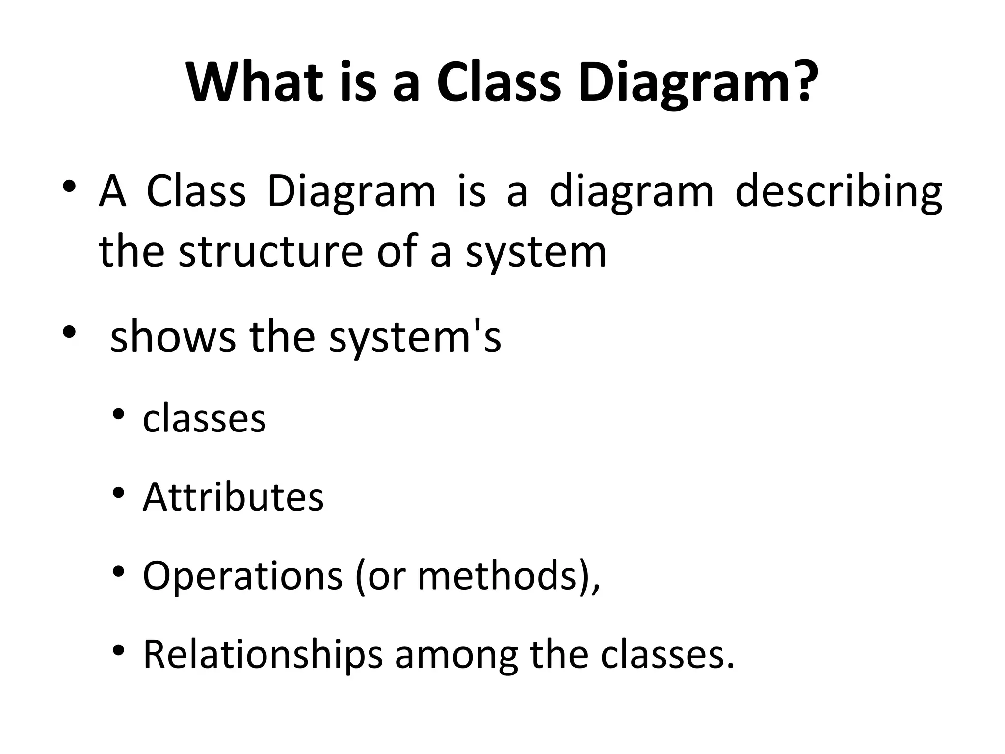
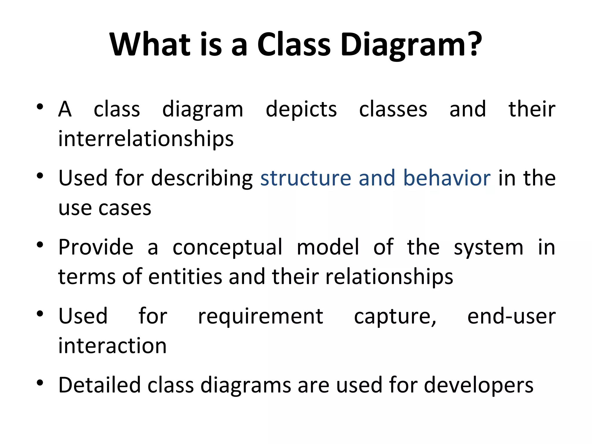
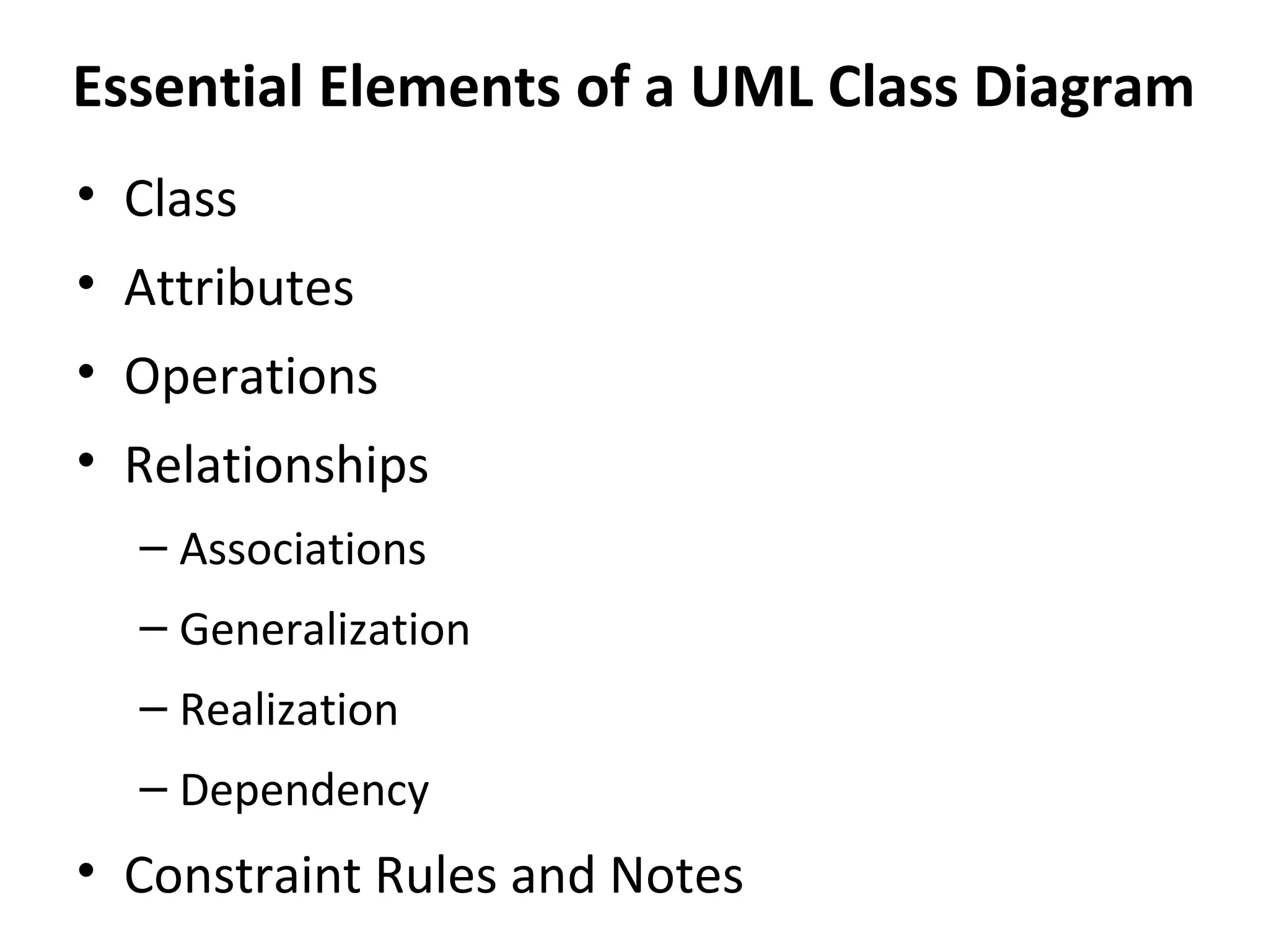
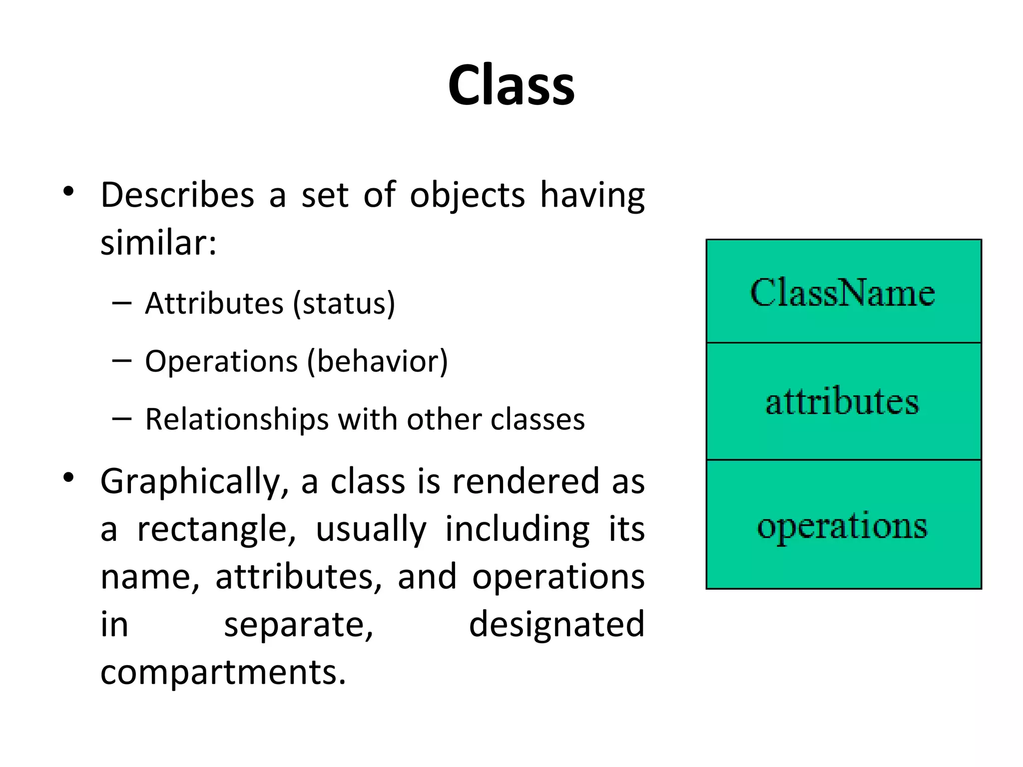
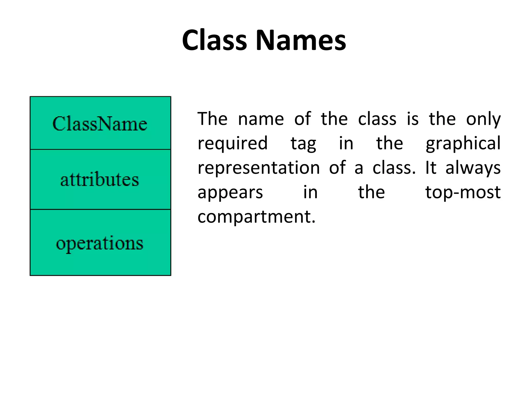
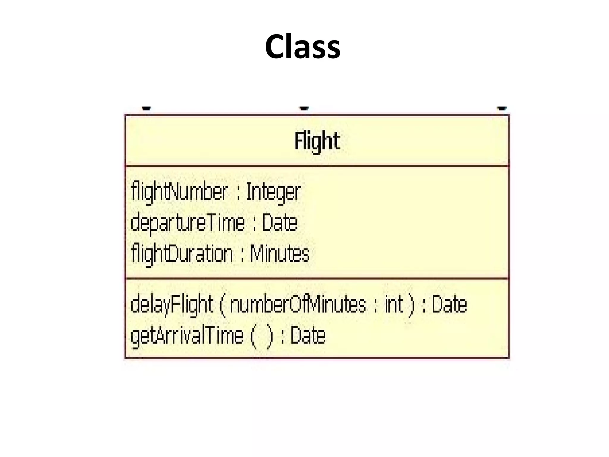

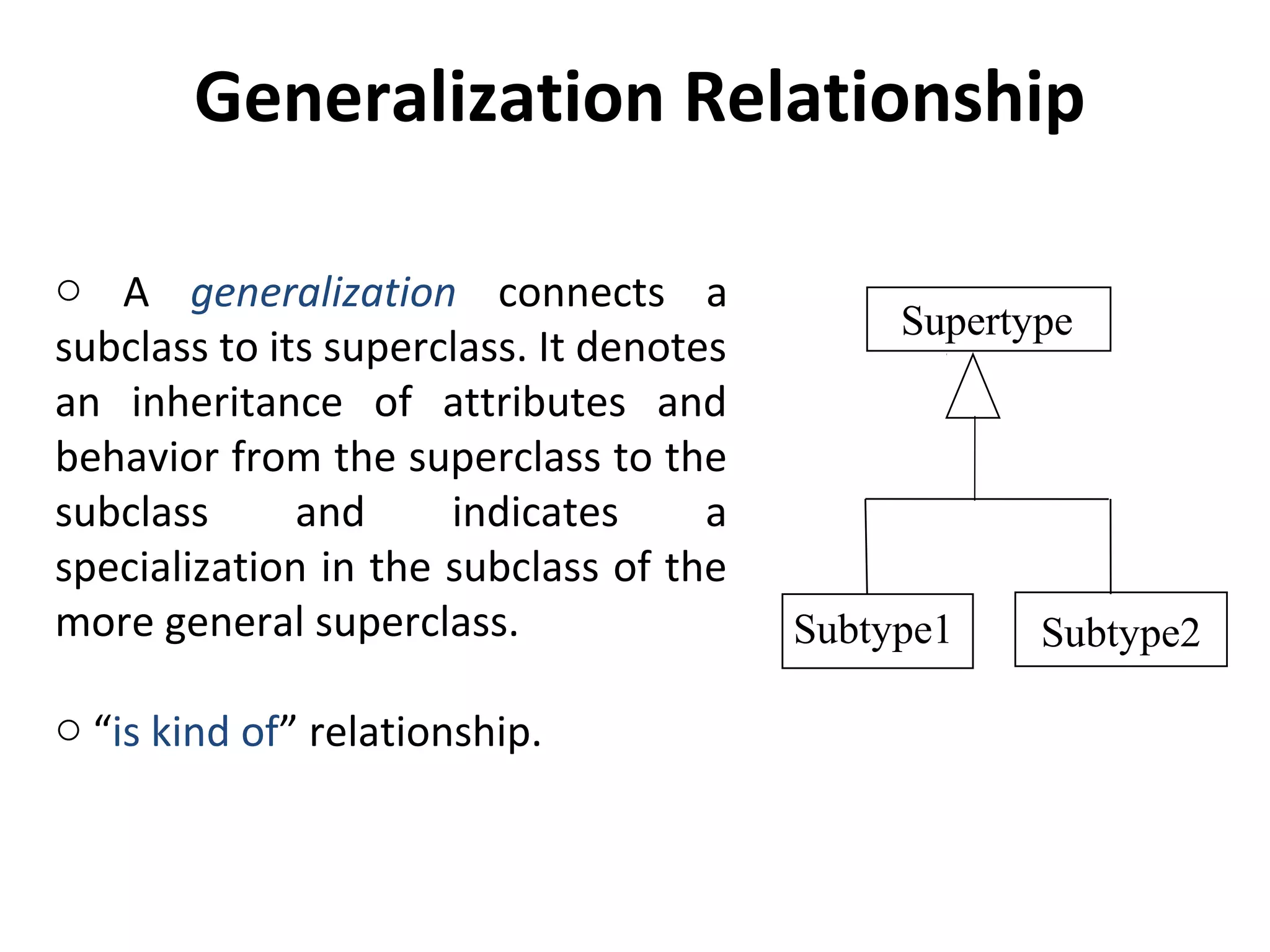
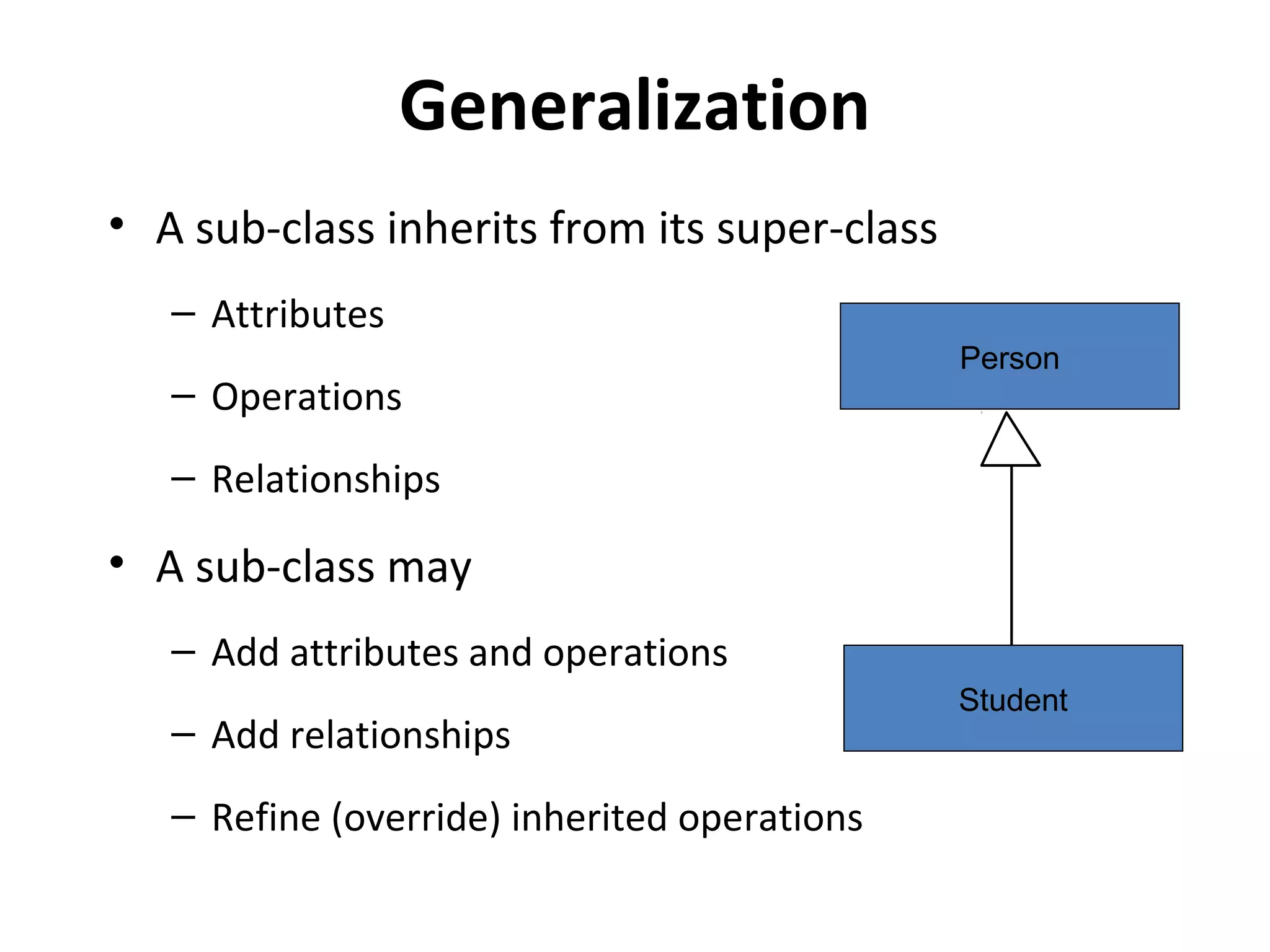
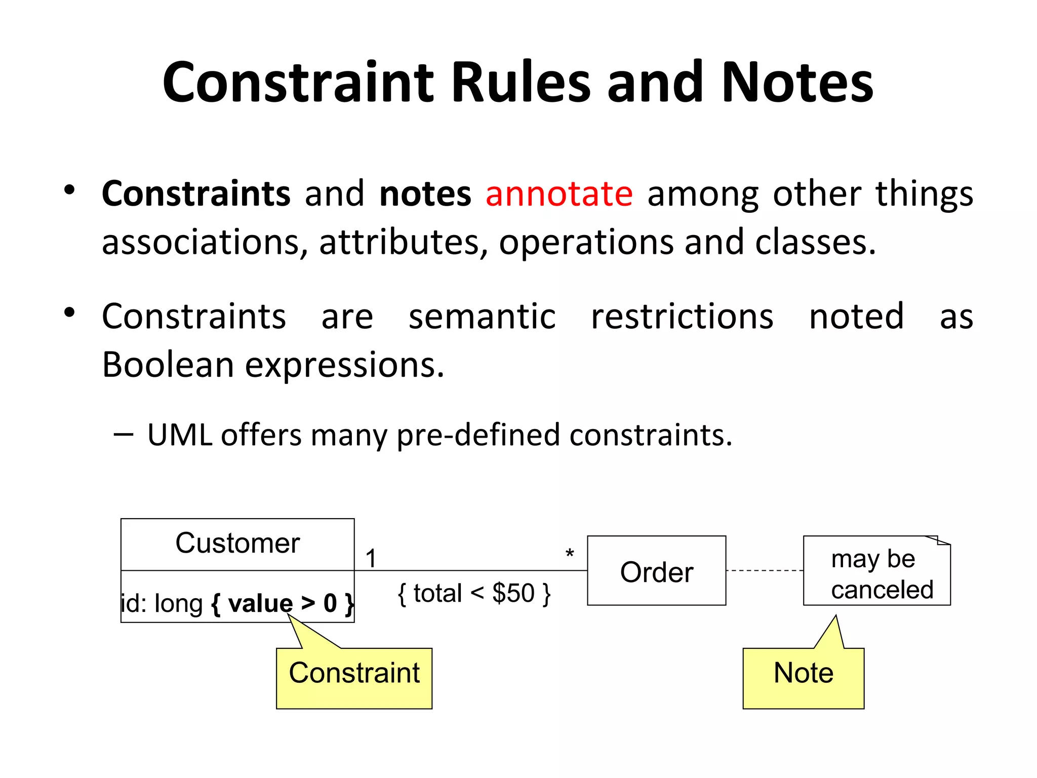
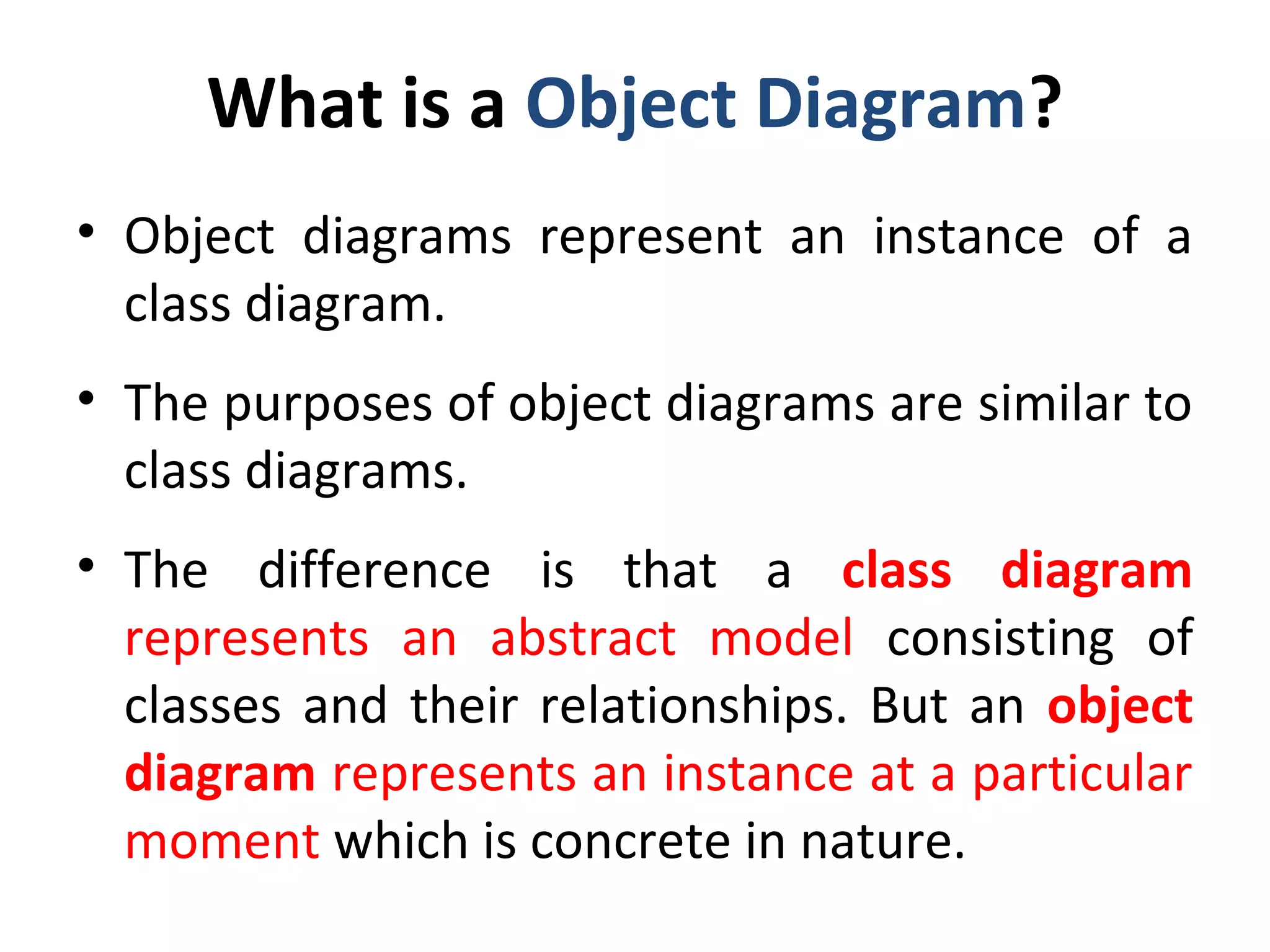
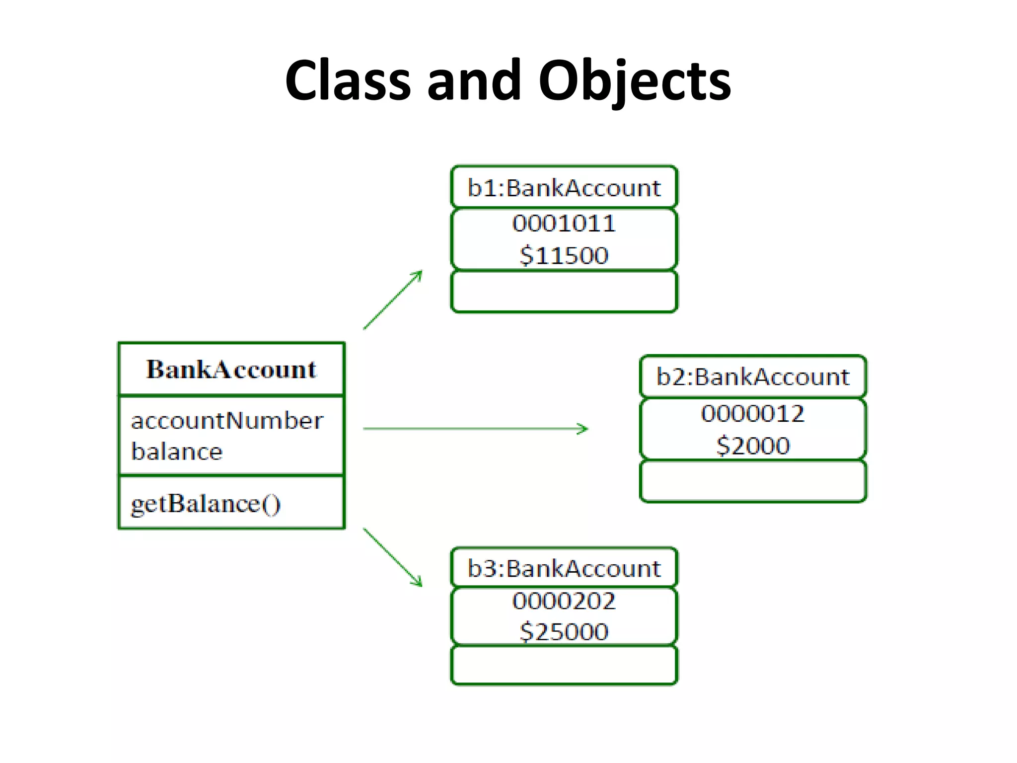

A class diagram shows the structure of a system by depicting classes, their attributes, operations, and relationships between classes. It is used for requirement capture, end-user interaction, and development. A class diagram depicts classes and their interrelationships through associations like generalization, aggregation, and composition. It also shows constraints and notes. An object diagram represents a concrete instance of a class diagram at a particular moment by showing specific objects.