CLASS DIAGRAMS IN OBJECT ORIENTED ANALYSIS AND DESIGN
1.
CLASS DIAGRAMS
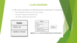
• InUML classes and objects are depicted by boxes comprising of 3 compartments.
The top displays the name of the class or object.
The center displays the attributes and
the bottom displays the operations.
2.
RELATIONSHIP IN CLASSDIAGRAMS
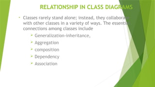
• Classes rarely stand alone; instead, they collaborate
with other classes in a variety of ways. The essential
connections among classes include
Generalization-inheritance,
Aggregation
composition
Dependency
Association
3.
INHERITANCE
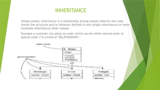
Simply stated, inheritanceis a relationship among classes wherein one class
shares the structure and/or behavior defined in one (single inheritance) or more
(multiple inheritance) other classes.
Example a customer can place an order which can be either normal order or
special order ("is-a-kind-of" RELATIONSHIP)
4.
AGGREGATION
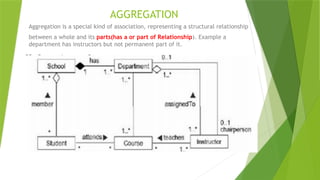
Aggregation is aspecial kind of association, representing a structural relationship
between a whole and its parts(has a or part of Relationship). Example a
department has instructors but not permanent part of it.
5.
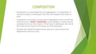
COMPOSITION
• Composition isa specialized form of aggregation. In composition, if
the parent object is destroyed, then the child objects also cease to
exist
• Composition is actually a strong type of aggregation and is sometimes
referred to as a “death” relationship. As an example, a house may be
composed of one or more rooms. If the house is destroyed, then all of
the rooms that are part of the house are also destroyed.
• Example the school has departments and can’t exist without the
departments and vice versa.
6.
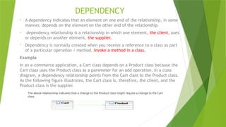
DEPENDENCY
• A dependencyindicates that an element on one end of the relationship, in some
manner, depends on the element on the other end of the relationship.
• dependency relationship is a relationship in which one element, the client, uses
or depends on another element, the supplier.
• Dependency is normally created when you receive a reference to a class as part
of a particular operation / method. Invoke a method in a class.
Example
In an e-commerce application, a Cart class depends on a Product class because the
Cart class uses the Product class as a parameter for an add operation. In a class
diagram, a dependency relationship points from the Cart class to the Product class.
As the following figure illustrates, the Cart class is, therefore, the client, and the
Product class is the supplier.
The above relationship indicates that a change to the Product class might require a change to the Cart
class.
7.
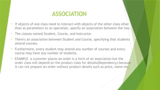
ASSOCIATION
• if objectsof one class need to interact with objects of the other class other
than as parameters to an operation, specify an association between the two.
• The classes named Student, Course, and Instructor.
• There's an association between Student and Course, specifying that students
attend courses.
• Furthermore, every student may attend any number of courses and every
course may have any number of students.
• EXAMPLE a customer places an order is a form of an association but the
order class will depend on the product class for details(Dependency) because
it can not prepare an order without product details such as price, name etc.
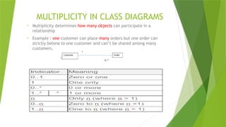
MULTIPLICITY IN CLASSDIAGRAMS
• Multiplicity determines how many objects can participate in a
relationship
• Example : one customer can place many orders but one order can
strictly belong to one customer and can’t be shared among many
customers.
10.
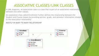
ASSOCIATIVE CLASSES/LINK CLASSES
InUML diagrams, an association class is a class that is part of an association relationship
between two other classes.
An association class called Enrollment further defines the relationship between the
Student and Course classes by providing section, grade, and semester information related
to the association relationship.
MOSTLY IN MANY TO MANY RELATIONSHIP
11.
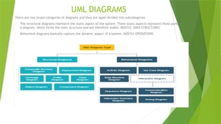
UML DIAGRAMS
There aretwo broad categories of diagrams and they are again divided into subcategories
o The structural diagrams represent the static aspect of the system. These static aspects represent those parts of
a diagram, which forms the main structure and are therefore stable. MOSTLY DATA STRUCTURES
o Behavioral diagrams basically capture the dynamic aspect of a system. MOSTLY OPERATIONS
12.
UML DIAGRAMS
A usecase represents a particular functionality of a system. Hence, use case diagram is
used to describe the relationships among the functionalities and their internal/external
controllers.
A sequence diagram is an interaction diagram. From the name, it is clear that the
diagram deals with some sequences, which are the sequence of messages flowing from
one object to another.
Any real-time system is expected to be reacted by some kind of internal/external events.
These events are responsible for state change of the system.
State chart diagram is used to represent the event driven state change of a system
Activity diagram describes the flow of control in a system. It consists of activities and
links. The flow can be sequential, concurrent, or branched. Activities are nothing but the
functions of a system. Numbers of activity diagrams are prepared to capture the entire
flow in a system
13.
CLASS EXERCISE
TO BEEMAILED TODAY.
KINDLY DO IT IN YOUR RESPECTIVE GROUPS
MAX 4 IN A GROUP