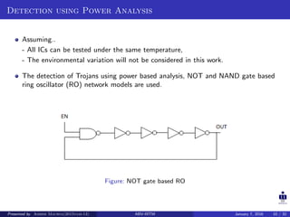
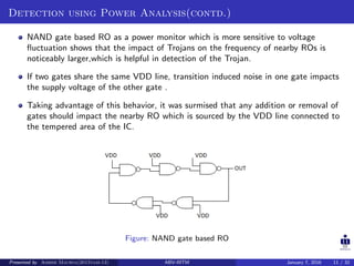
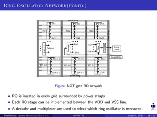
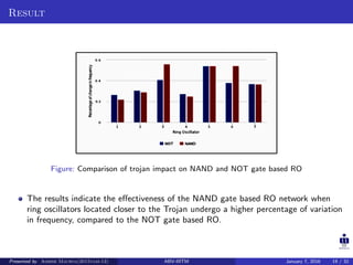
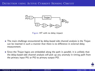
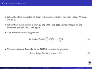
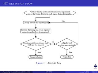
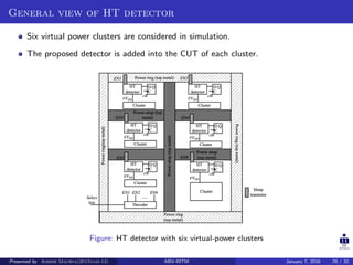
Detection of Hardware Trojans using Side Channel
Analysis
Presented by
Ashish Maurya
(2015vlsi-13)
ABV-Indian Institute of Information Technology and Management Gwalior,
Morena Link Road, Gwalior, Madhya Pradesh, INDIA - 474015.
January 7, 2016
Presented by Ashish Maurya(2015vlsi-13) ABV-IIITM January 7, 2016 1 / 32
Contents
1 Introduction
2 Detection Techniques
3 Conclusion
4 References
Presented by Ashish Maurya(2015vlsi-13) ABV-IIITM January 7, 2016 2 / 32
Introduction
Electronic systems available in today’s commercial, industrial and military sectors are
massive networks of ICs.
A part or whole of the IC supply chain is situated on different land, which is not
under surveillance.
This provides an opportunity for an adversary to embed functionality not stated in
the specification of the device.
With HT an adversary can extract the secret information by exploiting a physical
modality i.e.
- Power consumption,
- Delay,
- Electromagnetic emission
of the hardware that executes the target application.
Presented by Ashish Maurya(2015vlsi-13) ABV-IIITM January 7, 2016 3 / 32
Introduction(contd.)
Figure: General structure of Hardware Trojan
The trigger acts like a sensing circuitry, which activates a Trojan to perform a
specific task.
The payload is responsible for the malicious activity of the Trojan or effect of the
Trojan.
Presented by Ashish Maurya(2015vlsi-13) ABV-IIITM January 7, 2016 4 / 32
Introduction(contd.)
Figure: Different Payload insertion approaches
Presented by Ashish Maurya(2015vlsi-13) ABV-IIITM January 7, 2016 5 / 32
Introduction(contd.)
Figure: Trojans with capability of leaking secret information from inside a crypto chip through
power side channels
MOLES circuit is designed to consume data-dependent power as a power
side-channel to leak multi-bit secret keys.
Presented by Ashish Maurya(2015vlsi-13) ABV-IIITM January 7, 2016 6 / 32
Introduction(contd.)
Side-channels are the inherent physical properties of a running IC, including timing,
power consumption, electromagnetic radiation and even sound wave.
During testing or normal operation, for a very brief period of time the Trojan circuit
may receive input patterns which activate some of its gates.
Occurrence of signal transition at the input of the Trojan gates is very likely to cause
power or delay variation.
Side channel analysis though promising, must deal with major challenges due to rare
activating nets in the circuit, process variations, and measurement noise.
Presented by Ashish Maurya(2015vlsi-13) ABV-IIITM January 7, 2016 7 / 32
Introduction(contd.)
To improve the effectiveness of these detection methods, ICs must be designed with
some detection strategies in mind.
Trust must be considered as an important design criterion in the design flow of
modern ICs instead of being an afterthought.
A golden or Trojan free IC signature is required for comparison purpose in many of
these side channel analysis.
Such signature might be obtained by destructive reverse engineering approach or
from the software simulation of the original design.
Presented by Ashish Maurya(2015vlsi-13) ABV-IIITM January 7, 2016 8 / 32
Detection Techniques
DETECTION USING POWER ANALYSIS
Source: Assessment of NAND based ring oscillator for hardware Trojan detection,
IEEE 58th International Midwest Symposium 2015 Circuits and Systems
(MWSCAS), 2015
DETECTION USING ACTIVE CURRENT SENSING CIRCUIT
Source: A Cluster-Based Distributed Active Current Sensing Circuit for Hardware
Trojan Detection, IEEE Transactions on Information Forensics and Security, VOL. 9,
NO. 12, DECEMBER 2014
Presented by Ashish Maurya(2015vlsi-13) ABV-IIITM January 7, 2016 9 / 32
Detection using Power Analysis
Assuming..
- All ICs can be tested under the same temperature,
- The environmental variation will not be considered in this work.
The detection of Trojans using power based analysis, NOT and NAND gate based
ring oscillator (RO) network models are used.
Figure: NOT gate based RO
Presented by Ashish Maurya(2015vlsi-13) ABV-IIITM January 7, 2016 10 / 32
Detection using Power Analysis(contd.)
NAND gate based RO as a power monitor which is more sensitive to voltage
fluctuation shows that the impact of Trojans on the frequency of nearby ROs is
noticeably larger,which is helpful in detection of the Trojan.
If two gates share the same VDD line, transition induced noise in one gate impacts
the supply voltage of the other gate .
Taking advantage of this behavior, it was surmised that any addition or removal of
gates should impact the nearby RO which is sourced by the VDD line connected to
the tempered area of the IC.
Figure: NAND gate based RO
Presented by Ashish Maurya(2015vlsi-13) ABV-IIITM January 7, 2016 11 / 32
Detection using Power Analysis (contd.)
The delay of each gate varies according to parameters such as temperature, supply
voltage (VDD), load capacitance (CL), threshold voltage (Vth),channel length (L),
oxide thickness (Tox), and transistor channel width (W).
Power suppy noise which is also called voltage drop impacts the delay of gates.
f =
1
2 ∗ n ∗ td
(1)
The delay of the gates will change when voltage fluctuate.
This change in delay results some effect on oscillation frequency.
So for same input pattern, power supply noise will affect differently to Trojan free IC
and having Trojan IC.
Presented by Ashish Maurya(2015vlsi-13) ABV-IIITM January 7, 2016 12 / 32
Adopted Trojan circuit for analysis
Figure: Single stage of trojan design
Four similar stages constitute the Trojan design, these 20 Trojan gates are placed in
the 10 empty slices that were kept empty in the Trojan Free version of CUA.
The first stage of the Trojan obtains input from the LFSR and the rest of the stages
are supplied by the output of the previous stage.
Such design of Trojan guarantees partial activation during the circuit operation
which should impact the nearby ROs.
Presented by Ashish Maurya(2015vlsi-13) ABV-IIITM January 7, 2016 13 / 32
Experimental Setup and RO controller
Figure: Experimental Setup
Figure: RO controller
Presented by Ashish Maurya(2015vlsi-13) ABV-IIITM January 7, 2016 14 / 32
Ring Oscillator Network
Figure: RO network implemented over CUA on FPGA
Presented by Ashish Maurya(2015vlsi-13) ABV-IIITM January 7, 2016 15 / 32
Ring Oscillator Network(contd.)
Figure: NOT gate RO network
RO is inserted in every grid surrounded by power straps.
Each RO stage can be implemented between the VDD and VSS line.
A decoder and multiplexer are used to select which ring oscillator is measured.
Presented by Ashish Maurya(2015vlsi-13) ABV-IIITM January 7, 2016 16 / 32
Ring Oscillator Network(contd.)
RON is developed with the ability to detect Trojans that cause power fluctuations,
thereby uncovering the malicious inclusion.
A number of ring oscillators (ROs) acting as power monitors, distributed across the
entire IC.
The output of each ring oscillator represents one part of the power signature of the
entire IC.
The number of ring oscillators, N-RO, could be adjusted according to the size of the
IC and sensitivity to Trojans.
The output of RON in Trojan-free ICs generates a power signature.
Data analysis is used to effectively distinguish the power differences caused by
Trojans from those of process variations, and identifies hardware Trojans inserted
into the IC.
Presented by Ashish Maurya(2015vlsi-13) ABV-IIITM January 7, 2016 17 / 32
HT detection Flow
Figure: Flow Graph
Presented by Ashish Maurya(2015vlsi-13) ABV-IIITM January 7, 2016 18 / 32
Result
Figure: Comparison of trojan impact on NAND and NOT gate based RO
The results indicate the effectiveness of the NAND gate based RO network when
ring oscillators located closer to the Trojan undergo a higher percentage of variation
in frequency, compared to the NOT gate based RO.
Presented by Ashish Maurya(2015vlsi-13) ABV-IIITM January 7, 2016 19 / 32
DETECTION USING ACTIVE CURRENT SENSING CIRCUIT
Source: A Cluster-Based Distributed Active Current Sensing Circuit for Hardware Trojan
Detection, IEEE Transactions on Information Forensics and Security, VOL. 9, NO. 12,
DECEMBER 2014
Presented by Ashish Maurya(2015vlsi-13) ABV-IIITM January 7, 2016 20 / 32
Detection using Active Current Sensing Circuit
Figure: HT with no delay impact
The main challenge encountered by delay-based side channel analysis is the Trojan
can be inserted in such a manner that there is no difference in external delay
measurement.
Since the Trojan logics are embedded along the path in parallel, it is unlikely that
the delay-based side channel analysis will pick up any anomaly in timing path from
the primary input PI1 or PI2 to primary output PO.
Presented by Ashish Maurya(2015vlsi-13) ABV-IIITM January 7, 2016 21 / 32
Detection using Active Current Sensing Circuit(contd.)
Figure: HT with no switching power impact
Figure shows an AND gate whose inputs are from the most significant bits of a
counter.
The Trojan can be triggered only after the counter has run for a much longer time
than any standard test time.
To realize the triggering mechanism, the inputs of the Trojan are connected to some
existing logic nodes of the original design.
It increase the path delay and switching activity duration even if the Trojan remains
dormant, this can be considered as a special case of Trojan with low switching
activity.
Presented by Ashish Maurya(2015vlsi-13) ABV-IIITM January 7, 2016 22 / 32
Current Sensing Circuit
Active current sensing circuit is used to extract a signature that encapsulates both
the timing and amplitude of switching activity from the transient power supply
current for HT detection.
Figure: Schematic of the current sensing to path delay monitoring circuit
Presented by Ashish Maurya(2015vlsi-13) ABV-IIITM January 7, 2016 23 / 32
Current Sensing Circuit(contd.)
The current sensing detector is built with a calibrator to adjust the current
comparator threshold against process variations.
When the current sensing HT is activated during normal circuit operation, the
measured characteristics of the power trace will change dramatically to alert for
anomalies.
Presented by Ashish Maurya(2015vlsi-13) ABV-IIITM January 7, 2016 24 / 32
Current Sensing Circuit(contd.)
The dynamic IR-drop across the on-resistance R(on) of the sleep transistor M(sleep)
can be sensed to provide the visibility of the active current for the CUT.
The dynamic current is mirrored to a current comparator to produce two voltage
transitions that will mark the path delay.
The comparator output is latched into a scannable flip-flop.
The latched output is propagated to an external output pin by daisy chaining the
scan flip-flops of all detectors.
The delay transition of the comparator output from each detector can be determined
from the corresponding scanned output by varying the phase shift between the
system clock and the sampling clock of the scan chain in the detectors.
Presented by Ashish Maurya(2015vlsi-13) ABV-IIITM January 7, 2016 25 / 32
Current mirror
When the sleep transistor M(sleep) is turned on initially, the gate voltage V(sleep)
will be 0.
When there is no current drawn by the CUT, the gate-source voltages of the
transistor pair (M1-M2) are equal.
The mirrored current is given by:
Im ≈ Ron(2µpCox
W
L
I1
3
)
1
2 (1 +
Icut
I1
) (1)
The on-resistance Formula for an NMOS transistor is given by:
Ron = 1/(µnCOX W /L)(VGS − Vt ) (2)
Presented by Ashish Maurya(2015vlsi-13) ABV-IIITM January 7, 2016 26 / 32
Current comparator
The current comparator compares the mirrored current against the quiescent current
comparator threshold to produce a high output voltage level.
The response time is improved at the expense of a reduced output voltage swing.
Therefore, an inverting stage is needed to restore its rail-to-rail output.
Figure: Schematic of the current comparator circuit
Presented by Ashish Maurya(2015vlsi-13) ABV-IIITM January 7, 2016 27 / 32
HT detection flow
Figure: HT detection flow
Presented by Ashish Maurya(2015vlsi-13) ABV-IIITM January 7, 2016 28 / 32
General view of HT detector
Six virtual power clusters are considered in simulation.
The proposed detector is added into the CUT of each cluster.
Figure: HT detector with six virtual-power clusters
Presented by Ashish Maurya(2015vlsi-13) ABV-IIITM January 7, 2016 29 / 32
Conclusion
It is inherently difficult for an attacker to remove the ring oscillator network, due to
(i) Its distributed placement throughout the entire IC and
(ii) The expected measurement results from each ring oscillator.
One major advantage of side channel analysis is the Trojans can be detected without
being fully triggered.
The circuit containing large no. of paths, trojan cannot be detected by these
detectors.
One of the critical issues regarding the side channel analysis method is the effect of
process and environmental variation and measurement noise.
Presented by Ashish Maurya(2015vlsi-13) ABV-IIITM January 7, 2016 30 / 32
References
Y. Cao, C.-H. Chang, and S. Chen, “A cluster-based distributed active current
sensing circuit for hardware trojan detection,” Information Forensics and Security,
IEEE Transactions on, vol. 9, no. 12, pp. 2220–2231, Dec 2014.
T. Hoque, M. Mustapa, F. Amsaad, and M. Niamat, “Assessment of nand based
ring oscillator for hardware trojan detection,” in Circuits and Systems (MWSCAS),
2015 IEEE 58th International Midwest Symposium on, Aug 2015, pp. 1–4.
A. Ferraiuolo, X. Zhang, and M. Tehranipoor, “Experimental analysis of a ring
oscillator network for hardware trojan detection in a 90nm asic,” in Computer-Aided
Design (ICCAD), 2012 IEEE/ACM International Conference on, Nov 2012, pp.
37–42.
S. K. Haider, C. Jin, M. Ahmad, D. M. Shila, O. Khan, and M. van Dijk, “Hatch: A
formal framework of hardware trojan design and detection,” Cryptology ePrint
Archive, Report 2014/943, 2014, http://eprint.iacr.org/.
Presented by Ashish Maurya(2015vlsi-13) ABV-IIITM January 7, 2016 31 / 32
Thank You
Presented by Ashish Maurya(2015vlsi-13) ABV-IIITM January 7, 2016 32 / 32

Hardware trojan detection technique using side channel analysis for hardware security

  • 1.
    Detection of HardwareTrojans using Side Channel Analysis Presented by Ashish Maurya (2015vlsi-13) ABV-Indian Institute of Information Technology and Management Gwalior, Morena Link Road, Gwalior, Madhya Pradesh, INDIA - 474015. January 7, 2016 Presented by Ashish Maurya(2015vlsi-13) ABV-IIITM January 7, 2016 1 / 32
  • 2.
    Contents 1 Introduction 2 DetectionTechniques 3 Conclusion 4 References Presented by Ashish Maurya(2015vlsi-13) ABV-IIITM January 7, 2016 2 / 32
  • 3.
    Introduction Electronic systems availablein today’s commercial, industrial and military sectors are massive networks of ICs. A part or whole of the IC supply chain is situated on different land, which is not under surveillance. This provides an opportunity for an adversary to embed functionality not stated in the specification of the device. With HT an adversary can extract the secret information by exploiting a physical modality i.e. - Power consumption, - Delay, - Electromagnetic emission of the hardware that executes the target application. Presented by Ashish Maurya(2015vlsi-13) ABV-IIITM January 7, 2016 3 / 32
  • 4.
    Introduction(contd.) Figure: General structureof Hardware Trojan The trigger acts like a sensing circuitry, which activates a Trojan to perform a specific task. The payload is responsible for the malicious activity of the Trojan or effect of the Trojan. Presented by Ashish Maurya(2015vlsi-13) ABV-IIITM January 7, 2016 4 / 32
  • 5.
    Introduction(contd.) Figure: Different Payloadinsertion approaches Presented by Ashish Maurya(2015vlsi-13) ABV-IIITM January 7, 2016 5 / 32
  • 6.
    Introduction(contd.) Figure: Trojans withcapability of leaking secret information from inside a crypto chip through power side channels MOLES circuit is designed to consume data-dependent power as a power side-channel to leak multi-bit secret keys. Presented by Ashish Maurya(2015vlsi-13) ABV-IIITM January 7, 2016 6 / 32
  • 7.
    Introduction(contd.) Side-channels are theinherent physical properties of a running IC, including timing, power consumption, electromagnetic radiation and even sound wave. During testing or normal operation, for a very brief period of time the Trojan circuit may receive input patterns which activate some of its gates. Occurrence of signal transition at the input of the Trojan gates is very likely to cause power or delay variation. Side channel analysis though promising, must deal with major challenges due to rare activating nets in the circuit, process variations, and measurement noise. Presented by Ashish Maurya(2015vlsi-13) ABV-IIITM January 7, 2016 7 / 32
  • 8.
    Introduction(contd.) To improve theeffectiveness of these detection methods, ICs must be designed with some detection strategies in mind. Trust must be considered as an important design criterion in the design flow of modern ICs instead of being an afterthought. A golden or Trojan free IC signature is required for comparison purpose in many of these side channel analysis. Such signature might be obtained by destructive reverse engineering approach or from the software simulation of the original design. Presented by Ashish Maurya(2015vlsi-13) ABV-IIITM January 7, 2016 8 / 32
  • 9.
    Detection Techniques DETECTION USINGPOWER ANALYSIS Source: Assessment of NAND based ring oscillator for hardware Trojan detection, IEEE 58th International Midwest Symposium 2015 Circuits and Systems (MWSCAS), 2015 DETECTION USING ACTIVE CURRENT SENSING CIRCUIT Source: A Cluster-Based Distributed Active Current Sensing Circuit for Hardware Trojan Detection, IEEE Transactions on Information Forensics and Security, VOL. 9, NO. 12, DECEMBER 2014 Presented by Ashish Maurya(2015vlsi-13) ABV-IIITM January 7, 2016 9 / 32
  • 10.
    Detection using PowerAnalysis Assuming.. - All ICs can be tested under the same temperature, - The environmental variation will not be considered in this work. The detection of Trojans using power based analysis, NOT and NAND gate based ring oscillator (RO) network models are used. Figure: NOT gate based RO Presented by Ashish Maurya(2015vlsi-13) ABV-IIITM January 7, 2016 10 / 32
  • 11.
    Detection using PowerAnalysis(contd.) NAND gate based RO as a power monitor which is more sensitive to voltage fluctuation shows that the impact of Trojans on the frequency of nearby ROs is noticeably larger,which is helpful in detection of the Trojan. If two gates share the same VDD line, transition induced noise in one gate impacts the supply voltage of the other gate . Taking advantage of this behavior, it was surmised that any addition or removal of gates should impact the nearby RO which is sourced by the VDD line connected to the tempered area of the IC. Figure: NAND gate based RO Presented by Ashish Maurya(2015vlsi-13) ABV-IIITM January 7, 2016 11 / 32
  • 12.
    Detection using PowerAnalysis (contd.) The delay of each gate varies according to parameters such as temperature, supply voltage (VDD), load capacitance (CL), threshold voltage (Vth),channel length (L), oxide thickness (Tox), and transistor channel width (W). Power suppy noise which is also called voltage drop impacts the delay of gates. f = 1 2 ∗ n ∗ td (1) The delay of the gates will change when voltage fluctuate. This change in delay results some effect on oscillation frequency. So for same input pattern, power supply noise will affect differently to Trojan free IC and having Trojan IC. Presented by Ashish Maurya(2015vlsi-13) ABV-IIITM January 7, 2016 12 / 32
  • 13.
    Adopted Trojan circuitfor analysis Figure: Single stage of trojan design Four similar stages constitute the Trojan design, these 20 Trojan gates are placed in the 10 empty slices that were kept empty in the Trojan Free version of CUA. The first stage of the Trojan obtains input from the LFSR and the rest of the stages are supplied by the output of the previous stage. Such design of Trojan guarantees partial activation during the circuit operation which should impact the nearby ROs. Presented by Ashish Maurya(2015vlsi-13) ABV-IIITM January 7, 2016 13 / 32
  • 14.
    Experimental Setup andRO controller Figure: Experimental Setup Figure: RO controller Presented by Ashish Maurya(2015vlsi-13) ABV-IIITM January 7, 2016 14 / 32
  • 15.
    Ring Oscillator Network Figure:RO network implemented over CUA on FPGA Presented by Ashish Maurya(2015vlsi-13) ABV-IIITM January 7, 2016 15 / 32
  • 16.
    Ring Oscillator Network(contd.) Figure:NOT gate RO network RO is inserted in every grid surrounded by power straps. Each RO stage can be implemented between the VDD and VSS line. A decoder and multiplexer are used to select which ring oscillator is measured. Presented by Ashish Maurya(2015vlsi-13) ABV-IIITM January 7, 2016 16 / 32
  • 17.
    Ring Oscillator Network(contd.) RONis developed with the ability to detect Trojans that cause power fluctuations, thereby uncovering the malicious inclusion. A number of ring oscillators (ROs) acting as power monitors, distributed across the entire IC. The output of each ring oscillator represents one part of the power signature of the entire IC. The number of ring oscillators, N-RO, could be adjusted according to the size of the IC and sensitivity to Trojans. The output of RON in Trojan-free ICs generates a power signature. Data analysis is used to effectively distinguish the power differences caused by Trojans from those of process variations, and identifies hardware Trojans inserted into the IC. Presented by Ashish Maurya(2015vlsi-13) ABV-IIITM January 7, 2016 17 / 32
  • 18.
    HT detection Flow Figure:Flow Graph Presented by Ashish Maurya(2015vlsi-13) ABV-IIITM January 7, 2016 18 / 32
  • 19.
    Result Figure: Comparison oftrojan impact on NAND and NOT gate based RO The results indicate the effectiveness of the NAND gate based RO network when ring oscillators located closer to the Trojan undergo a higher percentage of variation in frequency, compared to the NOT gate based RO. Presented by Ashish Maurya(2015vlsi-13) ABV-IIITM January 7, 2016 19 / 32
  • 20.
    DETECTION USING ACTIVECURRENT SENSING CIRCUIT Source: A Cluster-Based Distributed Active Current Sensing Circuit for Hardware Trojan Detection, IEEE Transactions on Information Forensics and Security, VOL. 9, NO. 12, DECEMBER 2014 Presented by Ashish Maurya(2015vlsi-13) ABV-IIITM January 7, 2016 20 / 32
  • 21.
    Detection using ActiveCurrent Sensing Circuit Figure: HT with no delay impact The main challenge encountered by delay-based side channel analysis is the Trojan can be inserted in such a manner that there is no difference in external delay measurement. Since the Trojan logics are embedded along the path in parallel, it is unlikely that the delay-based side channel analysis will pick up any anomaly in timing path from the primary input PI1 or PI2 to primary output PO. Presented by Ashish Maurya(2015vlsi-13) ABV-IIITM January 7, 2016 21 / 32
  • 22.
    Detection using ActiveCurrent Sensing Circuit(contd.) Figure: HT with no switching power impact Figure shows an AND gate whose inputs are from the most significant bits of a counter. The Trojan can be triggered only after the counter has run for a much longer time than any standard test time. To realize the triggering mechanism, the inputs of the Trojan are connected to some existing logic nodes of the original design. It increase the path delay and switching activity duration even if the Trojan remains dormant, this can be considered as a special case of Trojan with low switching activity. Presented by Ashish Maurya(2015vlsi-13) ABV-IIITM January 7, 2016 22 / 32
  • 23.
    Current Sensing Circuit Activecurrent sensing circuit is used to extract a signature that encapsulates both the timing and amplitude of switching activity from the transient power supply current for HT detection. Figure: Schematic of the current sensing to path delay monitoring circuit Presented by Ashish Maurya(2015vlsi-13) ABV-IIITM January 7, 2016 23 / 32
  • 24.
    Current Sensing Circuit(contd.) Thecurrent sensing detector is built with a calibrator to adjust the current comparator threshold against process variations. When the current sensing HT is activated during normal circuit operation, the measured characteristics of the power trace will change dramatically to alert for anomalies. Presented by Ashish Maurya(2015vlsi-13) ABV-IIITM January 7, 2016 24 / 32
  • 25.
    Current Sensing Circuit(contd.) Thedynamic IR-drop across the on-resistance R(on) of the sleep transistor M(sleep) can be sensed to provide the visibility of the active current for the CUT. The dynamic current is mirrored to a current comparator to produce two voltage transitions that will mark the path delay. The comparator output is latched into a scannable flip-flop. The latched output is propagated to an external output pin by daisy chaining the scan flip-flops of all detectors. The delay transition of the comparator output from each detector can be determined from the corresponding scanned output by varying the phase shift between the system clock and the sampling clock of the scan chain in the detectors. Presented by Ashish Maurya(2015vlsi-13) ABV-IIITM January 7, 2016 25 / 32
  • 26.
    Current mirror When thesleep transistor M(sleep) is turned on initially, the gate voltage V(sleep) will be 0. When there is no current drawn by the CUT, the gate-source voltages of the transistor pair (M1-M2) are equal. The mirrored current is given by: Im ≈ Ron(2µpCox W L I1 3 ) 1 2 (1 + Icut I1 ) (1) The on-resistance Formula for an NMOS transistor is given by: Ron = 1/(µnCOX W /L)(VGS − Vt ) (2) Presented by Ashish Maurya(2015vlsi-13) ABV-IIITM January 7, 2016 26 / 32
  • 27.
    Current comparator The currentcomparator compares the mirrored current against the quiescent current comparator threshold to produce a high output voltage level. The response time is improved at the expense of a reduced output voltage swing. Therefore, an inverting stage is needed to restore its rail-to-rail output. Figure: Schematic of the current comparator circuit Presented by Ashish Maurya(2015vlsi-13) ABV-IIITM January 7, 2016 27 / 32
  • 28.
    HT detection flow Figure:HT detection flow Presented by Ashish Maurya(2015vlsi-13) ABV-IIITM January 7, 2016 28 / 32
  • 29.
    General view ofHT detector Six virtual power clusters are considered in simulation. The proposed detector is added into the CUT of each cluster. Figure: HT detector with six virtual-power clusters Presented by Ashish Maurya(2015vlsi-13) ABV-IIITM January 7, 2016 29 / 32
  • 30.
    Conclusion It is inherentlydifficult for an attacker to remove the ring oscillator network, due to (i) Its distributed placement throughout the entire IC and (ii) The expected measurement results from each ring oscillator. One major advantage of side channel analysis is the Trojans can be detected without being fully triggered. The circuit containing large no. of paths, trojan cannot be detected by these detectors. One of the critical issues regarding the side channel analysis method is the effect of process and environmental variation and measurement noise. Presented by Ashish Maurya(2015vlsi-13) ABV-IIITM January 7, 2016 30 / 32
  • 31.
    References Y. Cao, C.-H.Chang, and S. Chen, “A cluster-based distributed active current sensing circuit for hardware trojan detection,” Information Forensics and Security, IEEE Transactions on, vol. 9, no. 12, pp. 2220–2231, Dec 2014. T. Hoque, M. Mustapa, F. Amsaad, and M. Niamat, “Assessment of nand based ring oscillator for hardware trojan detection,” in Circuits and Systems (MWSCAS), 2015 IEEE 58th International Midwest Symposium on, Aug 2015, pp. 1–4. A. Ferraiuolo, X. Zhang, and M. Tehranipoor, “Experimental analysis of a ring oscillator network for hardware trojan detection in a 90nm asic,” in Computer-Aided Design (ICCAD), 2012 IEEE/ACM International Conference on, Nov 2012, pp. 37–42. S. K. Haider, C. Jin, M. Ahmad, D. M. Shila, O. Khan, and M. van Dijk, “Hatch: A formal framework of hardware trojan design and detection,” Cryptology ePrint Archive, Report 2014/943, 2014, http://eprint.iacr.org/. Presented by Ashish Maurya(2015vlsi-13) ABV-IIITM January 7, 2016 31 / 32
  • 32.
    Thank You Presented byAshish Maurya(2015vlsi-13) ABV-IIITM January 7, 2016 32 / 32