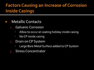
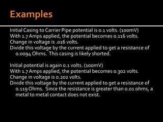
 ElectricalTests – Identify Problem & Prevent
Damage
1. Potential Survey
2. IsolationTester
3. Internal ResistanceTest
4. Four (4)Wire IR DropTest
5. Cycling RectifierTest
6. Casing DepolarizationTest
▪ Panhandle EasternTest
 Instrumented Pigs (Smart Pigs) – Problem
Identified, DamageAlready Done
1. Magnetic Flux
2. Ultrasonic
 Leakage Surveys –
Problem Identified,
Damage Already
Done
1. Visual Inspection
2. Instrumented Surveys
▪ Vent Sniffing
▪ Gas Detection Survey
 Coating Deterioration
1. Age
▪ Pipelines are getting older
2. Physical Damage
▪ Heat Damage
▪ Installation Damage
 Shielding
1. Spacers
▪ Dielectric Material in contact with Pipeline
2. Insulators
▪ Dielectric Material in contact with Pipeline
3. Coating
▪ Casing Coated or Non-metallic Material
 Metallic Contacts
1. Galvanic Corrosion
▪ Allow to occur at coating holiday inside casing
▪ No CP inside casing
2. Drain on CP System
▪ Large Bare Metal Surface added to CP System
3. Stress Concentrator
 Criteria
 Generally, a shorted casing may exist if the Pipe-
to-Soil versus Casing-to-Soil potential versus a
Copper-Copper Sulfate Electrode is less than
100mV
 Monitoring
 ElectricalTesting should be considered if the
potential difference is less than 100mV
Potential Survey
▪ Typically, this is the first test run
▪ Typically, done during Annual Survey
▪ RequiresVoltmeter and Reference Cell
▪ Only determines whether a shorted casing may
exist
Internal ResistanceTest
▪ Determines whether metal to metal contact exists
▪ Typically done as follow-up to Potential Survey
▪ RequiresVoltmeter and Reference Cell, plus battery,
shunt and variable resistor
▪ When Change inVoltage is divided by current flow, a
metal to metal contact may exist if less than .01 ohm
Initial Casing to Carrier Pipe potential is 0.1 volts. (100mV)
With 1.7Amps applied, the potential becomes 0.116 volts.
Change in voltage is .016 volts.
Divide this voltage by the current applied to get a resistance of
0.0094 Ohms. This casing is likely shorted.
Initial potential is again 0.1 volts. (100mV)
With 1.7Amps applied, the potential becomes 0.302 volts.
Change in voltage is 0.202 volts.
Divide this voltage by the current applied to get a resistance of
0.119 Ohms. Since the resistance is greater than 0.01 ohms, a
metal to metal contact does not exist.
Four (4)Wire IR DropTest
▪ Determines whether metal to metal contact exists
and demonstrates where the short is located
▪ Typically done as follow-up to OtherTests Prior to
Repair
▪ RequiresVoltmeter, plus battery, variable resistor,
probe bars, and pipe tables
▪ More complicated test
Measure mV potential from probe bars while passing measured current to
vents.
Determine change in voltage
0.465mV before current
1.500mV with current
1.035 Change
Divide current applied by millivolts to get Amp/mV factor
8.695A/mV
Verify ResultsVersus PipeTables and Casing Length for this particular pipe.
Drop Factor = 344.8 A/mV/ft divided by 40 feet
= 8.62A/mV
The results are within 5% (accuracy of this test) so proceed to Step 2.
Measure mV potential from probe bars while passing measured current to between casing and
carrier pipe.
In this example the calculated potential drop is 1.040mV
Multiply this potential drop by the factor calculated in Step 1 and divide this by the current
applied. Multiply the result by 100%
This gives a percent of current passing between terminals
In this example the calculated current is 99.99%
Verify ResultsVersus PipeTables and Casing Length for this particular pipe.
Resistance for Pipe = 2.90 micro ohms/ft
Length from positive terminal = 1.040mV x 10^-3 (makes it volts) divided by 9 Amps x (2.9 x
10^-6 ohms/ft)
= 39.85 ft
These results indicate the short is located at the downstream end of the casing 39.85 feet from
the positive terminal connection and that
99.99 % of the current is passing through the measured span.
Reconfigure current source equipment on downstream side
Measure mV potential from probe bars while passing measured current to
between casing and carrier pipe.
In this example the calculated potential drop is 0.00 mV
Multiply this potential drop by the factor calculated in Step 1 and divide this by
the current applied. Multiply the result by 100%
This gives a percent of current passing between terminals
In this example the calculated current is 0.0%
This result indicates the short is located at the downstream end since no
current passes through the test span. No further calculations are required.
Cycling Rectifier
▪ If casing is isolated no potential change will occur on
the casing with the rectifier cycling
▪ If the casing is shorted, the casing potential will
reflect that of the carrier pipe as the rectifier cycles
▪ Results are not always conclusive
▪ A slight change in casing potential when the carrier
potential changes significantly, may indicate
electrolytic short (Water/Soil in Casing)
▪ RequiresVoltmeter and Reference Cell
Casing DepolarizationTest (Panhandle Eastern )
▪ If a casing is isolated, in this test the potentials for the casing
and the carrier pipe will separate from each other when varying
amounts of current are applied
▪ If the casing is shorted, the casing and carrier pipe potentials will
remain near the same regardless of current applied
▪ RequiresVoltmeter and Reference Cell, plus a adjustable DC
power supply and temporary groundbed materials
1. Casing is Isolated
Carrier P/S CasingC/S Test Current
-1.340 -1.340 0.00Amps
-1.075 -1.070 1.00 Amps
-1.025 -0.790 2.00Amps
-0.910 -0.590 2.70 Amps
2. Casing is Shorted
Carrier P/S CasingC/S Test Current
-1.330 -1.330 0.00Amps
-1.300 -1.290 0.50 Amps
-1.260 -1.250 1.50 Amps
-1.110 -1.090 4.00Amps
Questions and Comments

Shorted Casing Study - Tim Sievert

  • 6.
     ElectricalTests –Identify Problem & Prevent Damage 1. Potential Survey 2. IsolationTester 3. Internal ResistanceTest 4. Four (4)Wire IR DropTest 5. Cycling RectifierTest 6. Casing DepolarizationTest ▪ Panhandle EasternTest
  • 8.
     Instrumented Pigs(Smart Pigs) – Problem Identified, DamageAlready Done 1. Magnetic Flux 2. Ultrasonic
  • 9.
     Leakage Surveys– Problem Identified, Damage Already Done 1. Visual Inspection 2. Instrumented Surveys ▪ Vent Sniffing ▪ Gas Detection Survey
  • 10.
     Coating Deterioration 1.Age ▪ Pipelines are getting older 2. Physical Damage ▪ Heat Damage ▪ Installation Damage
  • 11.
     Shielding 1. Spacers ▪Dielectric Material in contact with Pipeline 2. Insulators ▪ Dielectric Material in contact with Pipeline 3. Coating ▪ Casing Coated or Non-metallic Material
  • 12.
     Metallic Contacts 1.Galvanic Corrosion ▪ Allow to occur at coating holiday inside casing ▪ No CP inside casing 2. Drain on CP System ▪ Large Bare Metal Surface added to CP System 3. Stress Concentrator
  • 13.
     Criteria  Generally,a shorted casing may exist if the Pipe- to-Soil versus Casing-to-Soil potential versus a Copper-Copper Sulfate Electrode is less than 100mV  Monitoring  ElectricalTesting should be considered if the potential difference is less than 100mV
  • 14.
    Potential Survey ▪ Typically,this is the first test run ▪ Typically, done during Annual Survey ▪ RequiresVoltmeter and Reference Cell ▪ Only determines whether a shorted casing may exist
  • 16.
    Internal ResistanceTest ▪ Determineswhether metal to metal contact exists ▪ Typically done as follow-up to Potential Survey ▪ RequiresVoltmeter and Reference Cell, plus battery, shunt and variable resistor ▪ When Change inVoltage is divided by current flow, a metal to metal contact may exist if less than .01 ohm
  • 18.
    Initial Casing toCarrier Pipe potential is 0.1 volts. (100mV) With 1.7Amps applied, the potential becomes 0.116 volts. Change in voltage is .016 volts. Divide this voltage by the current applied to get a resistance of 0.0094 Ohms. This casing is likely shorted. Initial potential is again 0.1 volts. (100mV) With 1.7Amps applied, the potential becomes 0.302 volts. Change in voltage is 0.202 volts. Divide this voltage by the current applied to get a resistance of 0.119 Ohms. Since the resistance is greater than 0.01 ohms, a metal to metal contact does not exist.
  • 19.
    Four (4)Wire IRDropTest ▪ Determines whether metal to metal contact exists and demonstrates where the short is located ▪ Typically done as follow-up to OtherTests Prior to Repair ▪ RequiresVoltmeter, plus battery, variable resistor, probe bars, and pipe tables ▪ More complicated test
  • 21.
    Measure mV potentialfrom probe bars while passing measured current to vents. Determine change in voltage 0.465mV before current 1.500mV with current 1.035 Change Divide current applied by millivolts to get Amp/mV factor 8.695A/mV Verify ResultsVersus PipeTables and Casing Length for this particular pipe. Drop Factor = 344.8 A/mV/ft divided by 40 feet = 8.62A/mV The results are within 5% (accuracy of this test) so proceed to Step 2.
  • 24.
    Measure mV potentialfrom probe bars while passing measured current to between casing and carrier pipe. In this example the calculated potential drop is 1.040mV Multiply this potential drop by the factor calculated in Step 1 and divide this by the current applied. Multiply the result by 100% This gives a percent of current passing between terminals In this example the calculated current is 99.99% Verify ResultsVersus PipeTables and Casing Length for this particular pipe. Resistance for Pipe = 2.90 micro ohms/ft Length from positive terminal = 1.040mV x 10^-3 (makes it volts) divided by 9 Amps x (2.9 x 10^-6 ohms/ft) = 39.85 ft These results indicate the short is located at the downstream end of the casing 39.85 feet from the positive terminal connection and that 99.99 % of the current is passing through the measured span.
  • 27.
    Reconfigure current sourceequipment on downstream side Measure mV potential from probe bars while passing measured current to between casing and carrier pipe. In this example the calculated potential drop is 0.00 mV Multiply this potential drop by the factor calculated in Step 1 and divide this by the current applied. Multiply the result by 100% This gives a percent of current passing between terminals In this example the calculated current is 0.0% This result indicates the short is located at the downstream end since no current passes through the test span. No further calculations are required.
  • 28.
    Cycling Rectifier ▪ Ifcasing is isolated no potential change will occur on the casing with the rectifier cycling ▪ If the casing is shorted, the casing potential will reflect that of the carrier pipe as the rectifier cycles ▪ Results are not always conclusive ▪ A slight change in casing potential when the carrier potential changes significantly, may indicate electrolytic short (Water/Soil in Casing) ▪ RequiresVoltmeter and Reference Cell
  • 29.
    Casing DepolarizationTest (PanhandleEastern ) ▪ If a casing is isolated, in this test the potentials for the casing and the carrier pipe will separate from each other when varying amounts of current are applied ▪ If the casing is shorted, the casing and carrier pipe potentials will remain near the same regardless of current applied ▪ RequiresVoltmeter and Reference Cell, plus a adjustable DC power supply and temporary groundbed materials
  • 31.
    1. Casing isIsolated Carrier P/S CasingC/S Test Current -1.340 -1.340 0.00Amps -1.075 -1.070 1.00 Amps -1.025 -0.790 2.00Amps -0.910 -0.590 2.70 Amps 2. Casing is Shorted Carrier P/S CasingC/S Test Current -1.330 -1.330 0.00Amps -1.300 -1.290 0.50 Amps -1.260 -1.250 1.50 Amps -1.110 -1.090 4.00Amps
  • 39.