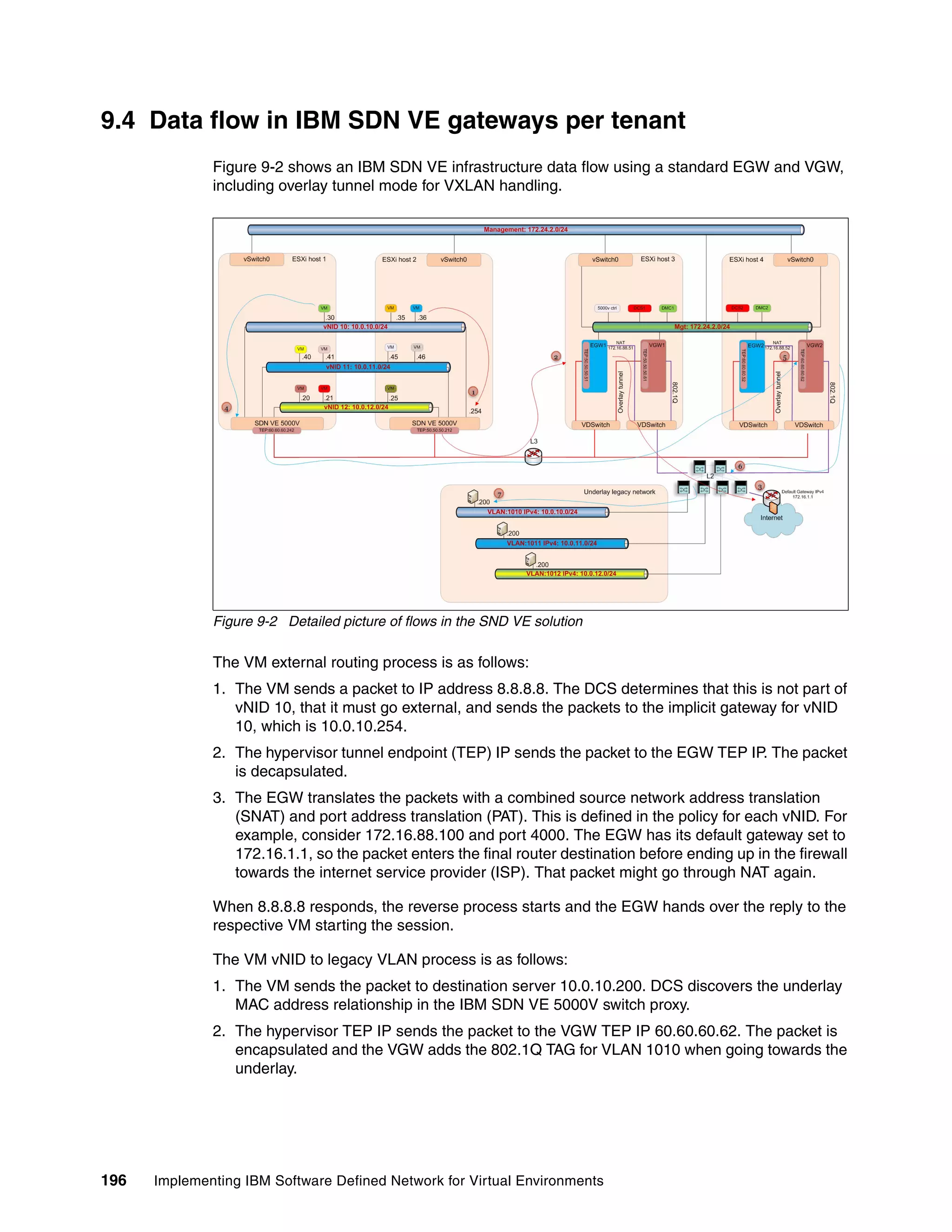
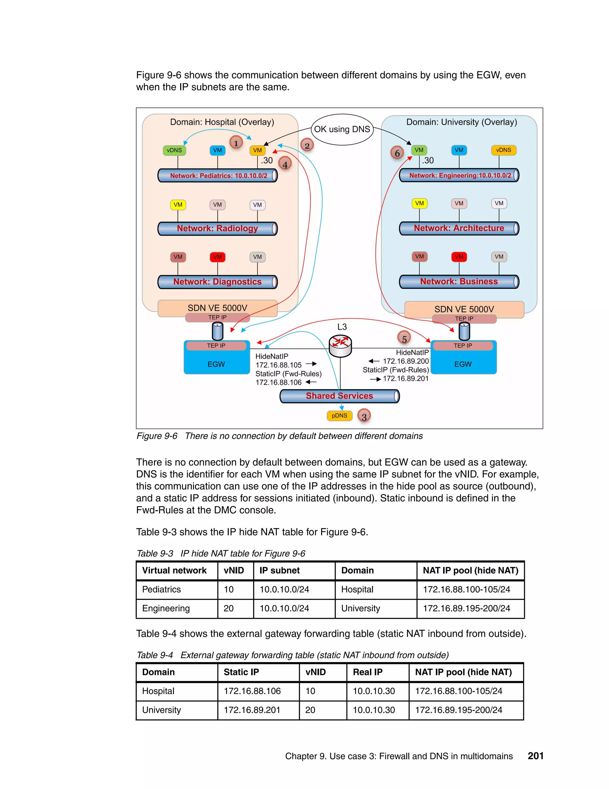
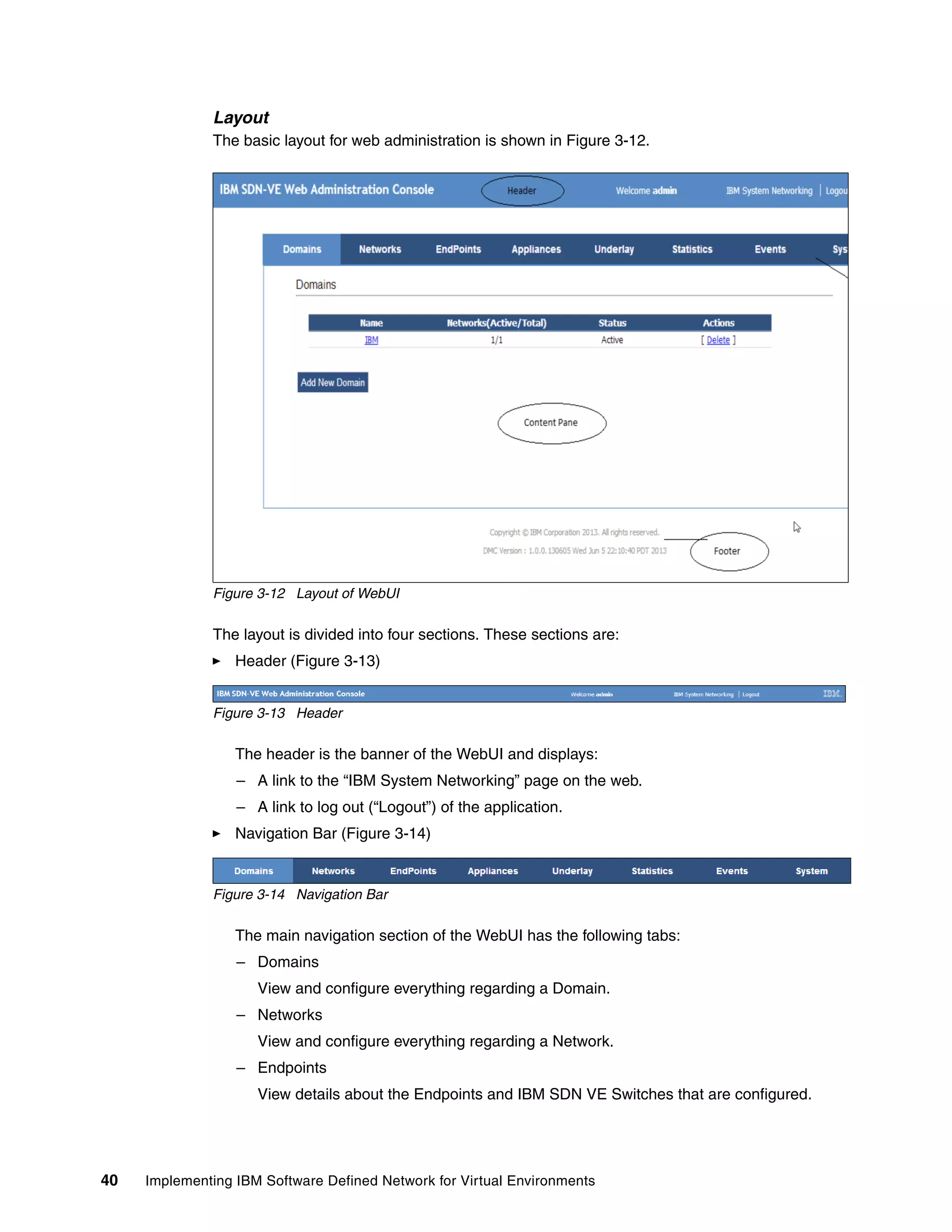
This document provides an overview and introduction to IBM's Software Defined Network for Virtual Environments (SDN VE) solution. It describes the components of SDN VE including the Distributed Services Appliance, Distributed Connectivity Service, Distributed Gateways, and 5000V Host Module. It also explains key concepts such as the overlay network, network encapsulation techniques, and how SDN VE addresses network segmentation challenges in virtualized environments.


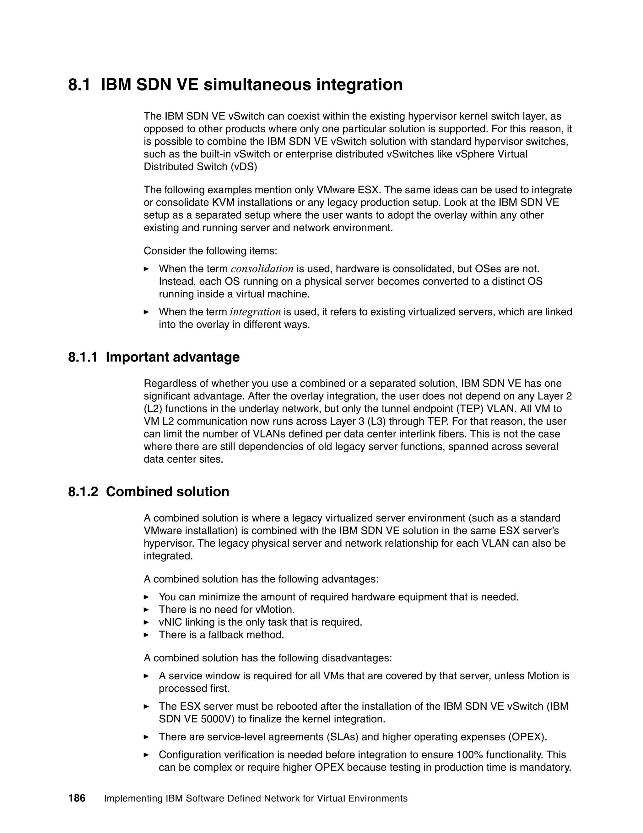
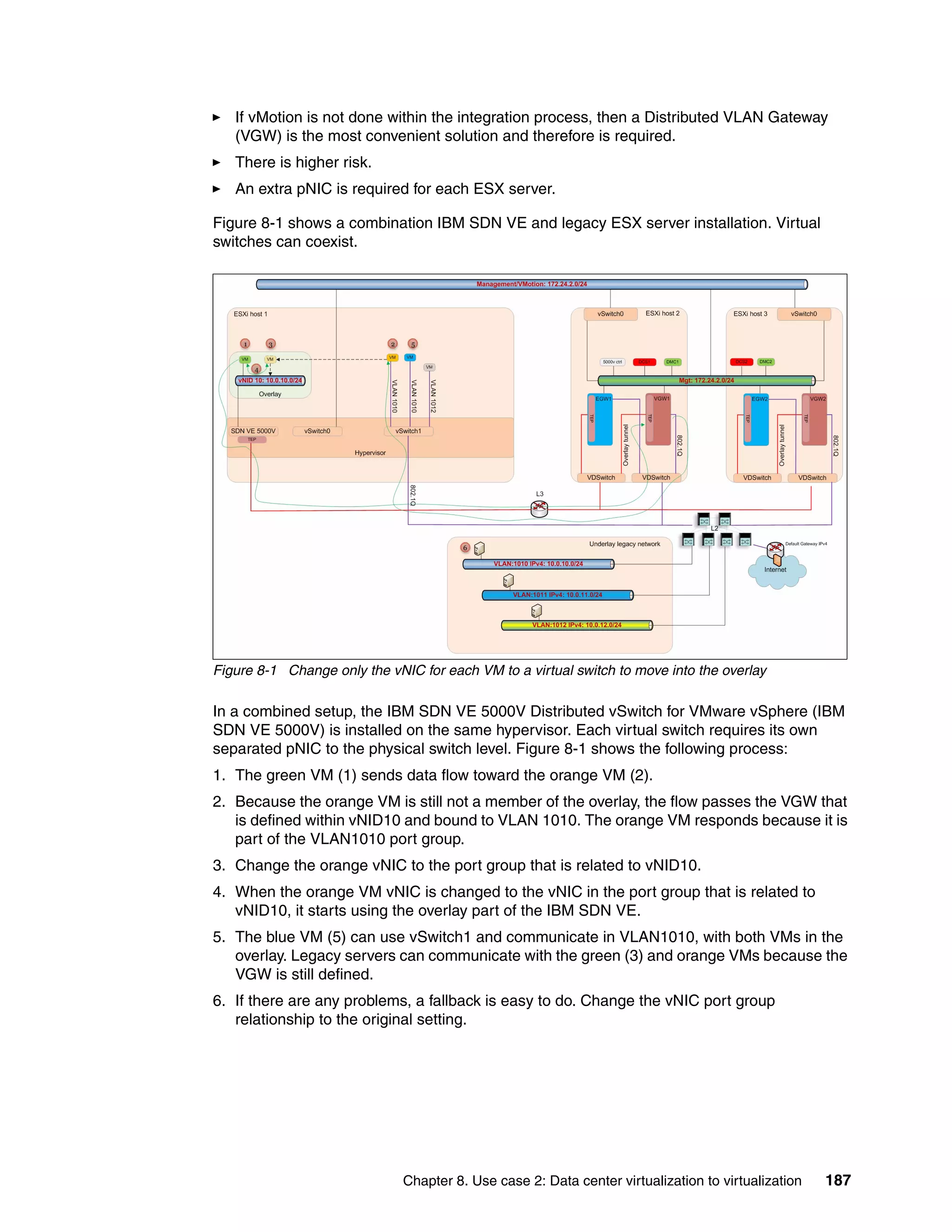
![46 Implementing IBM Software Defined Network for Virtual Environments
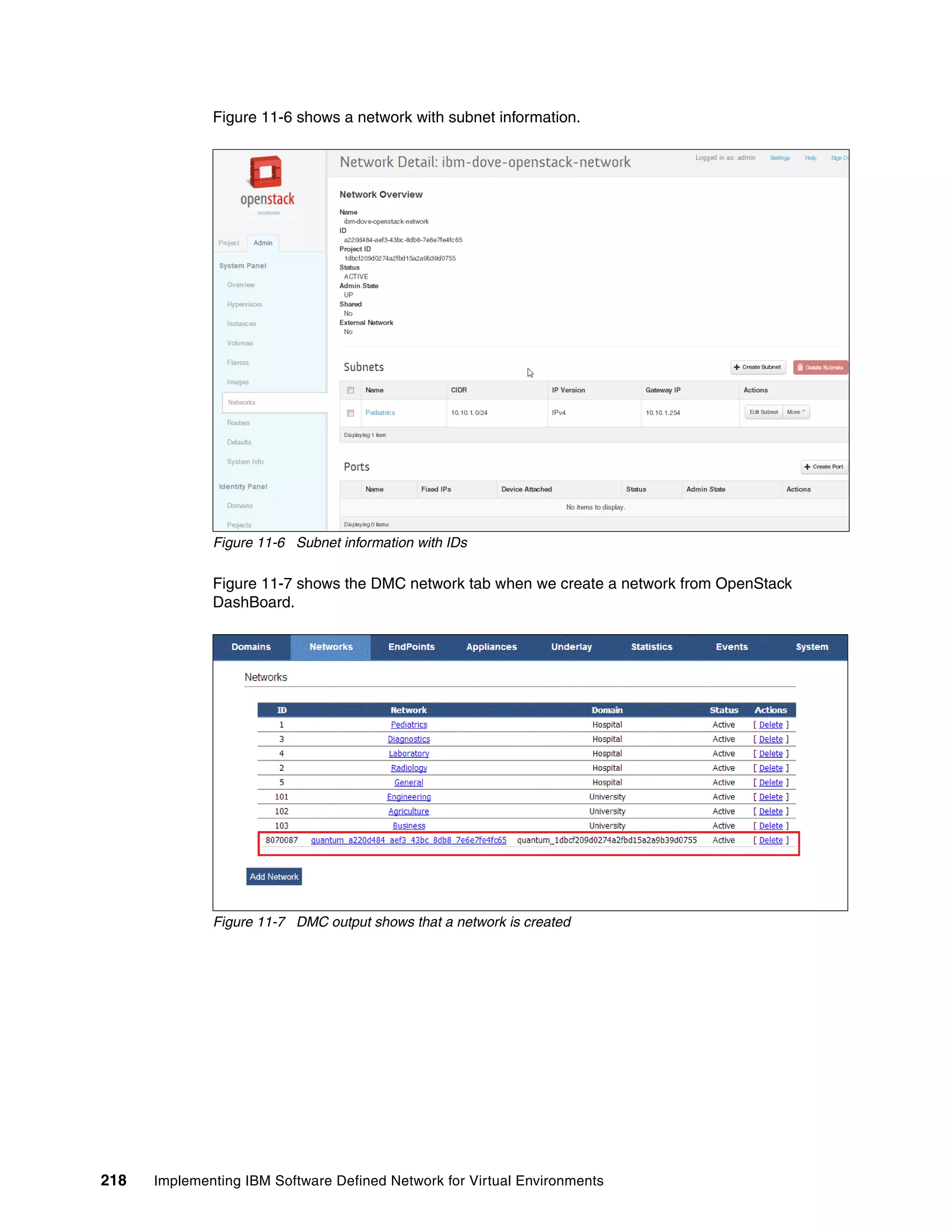
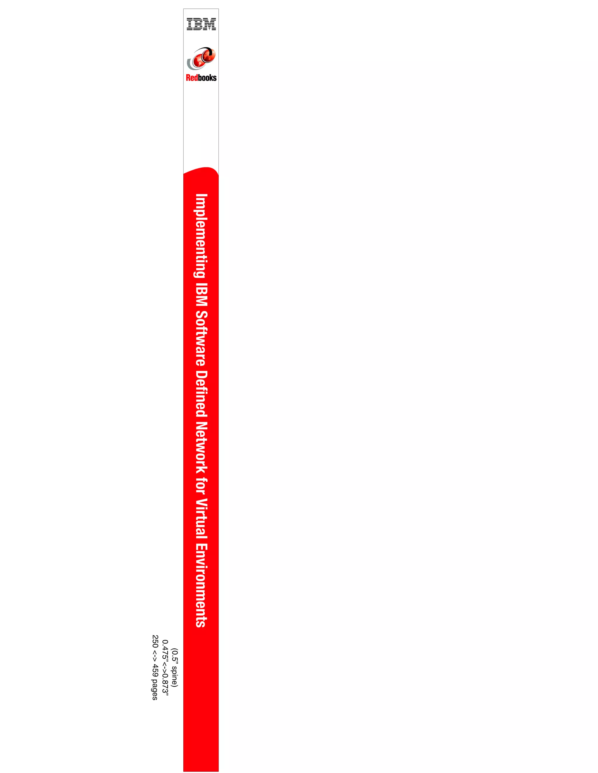
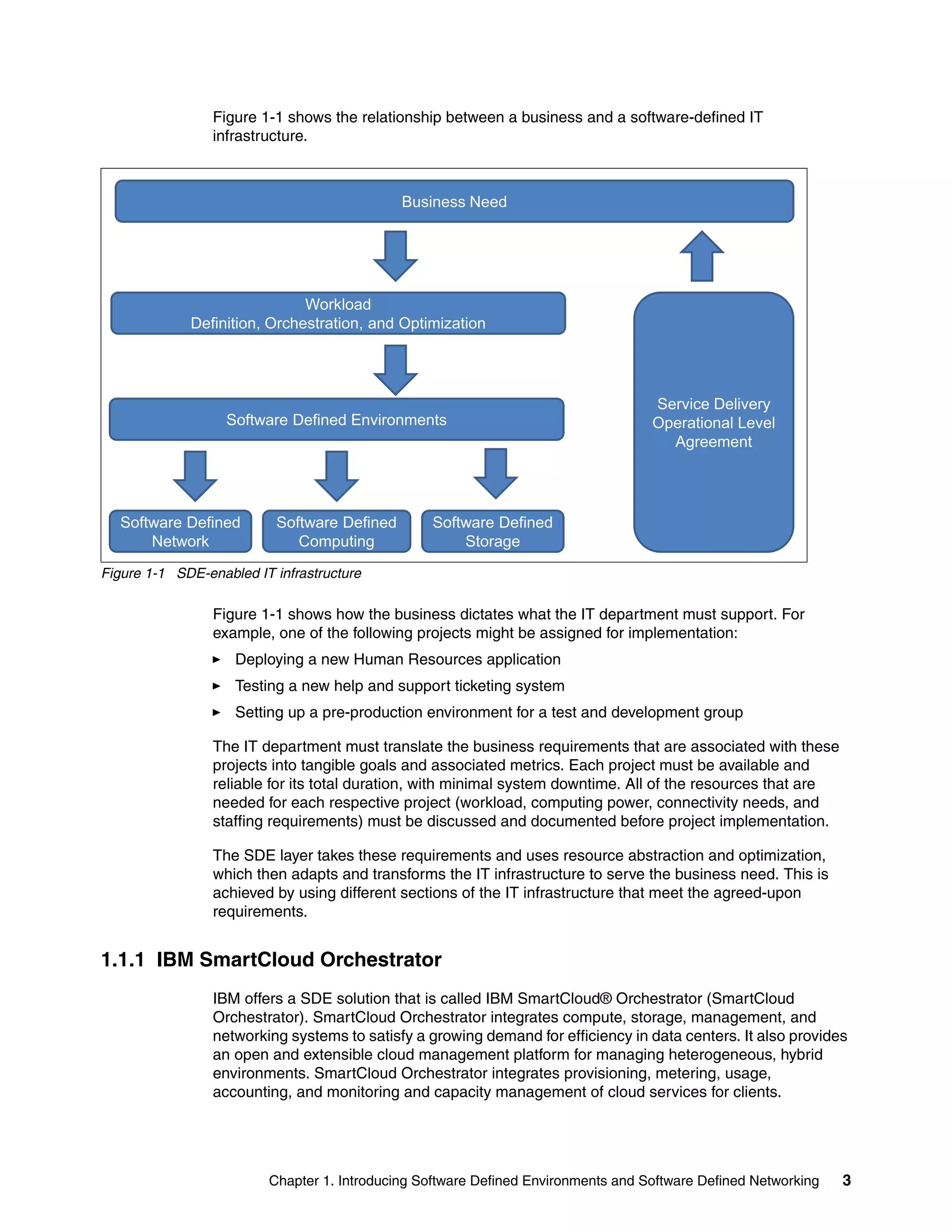
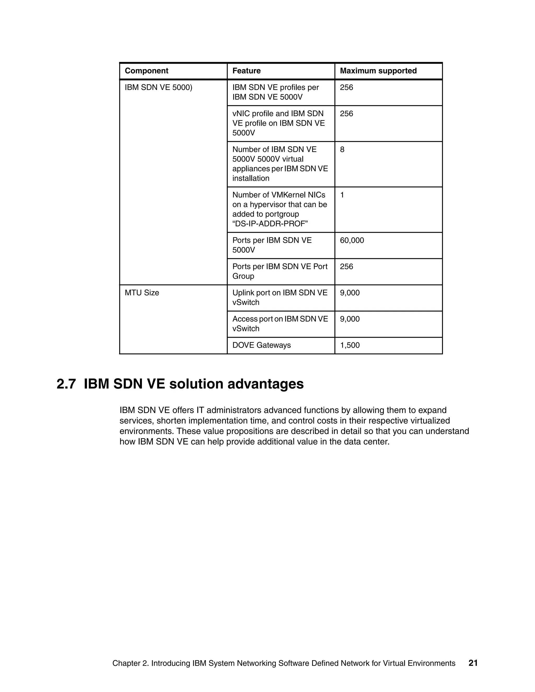
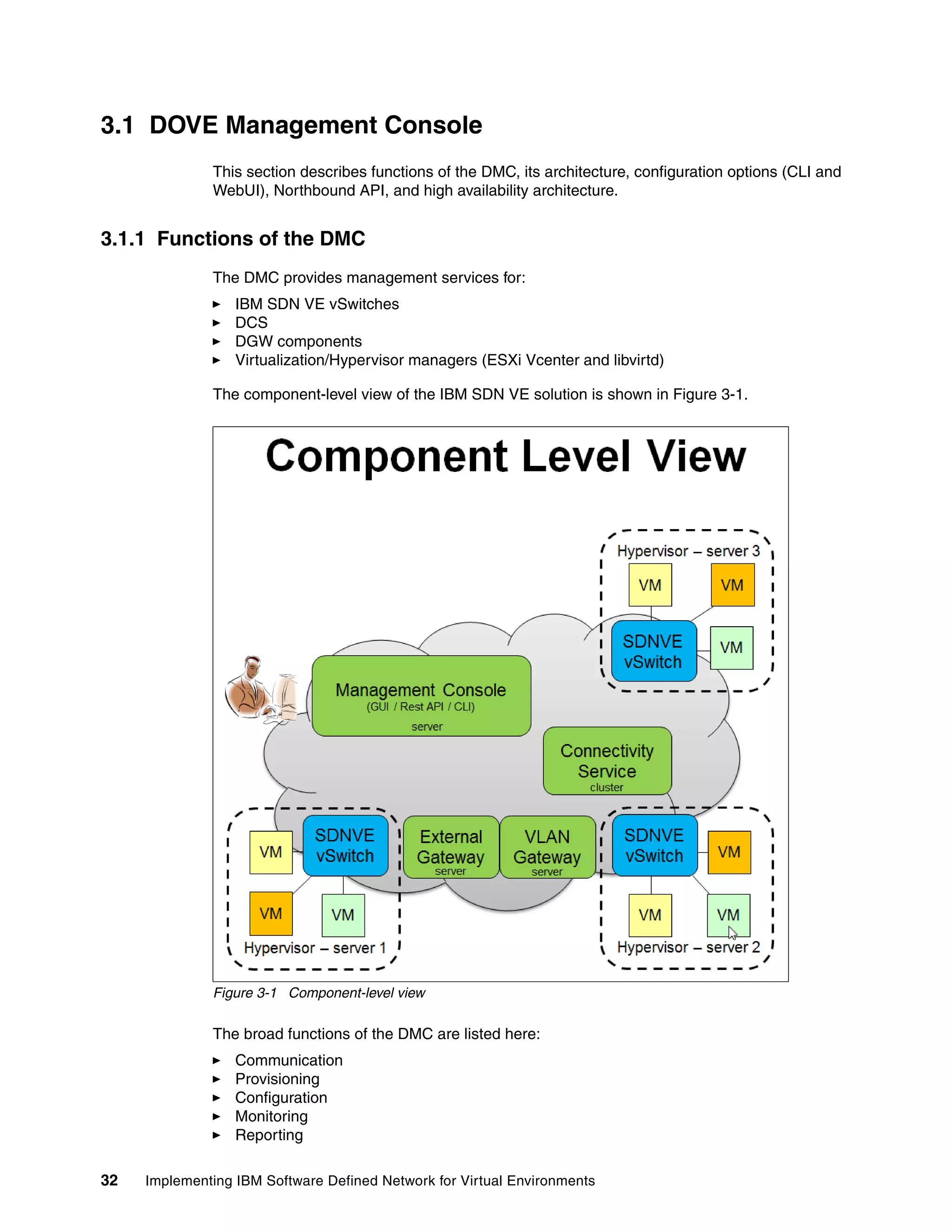
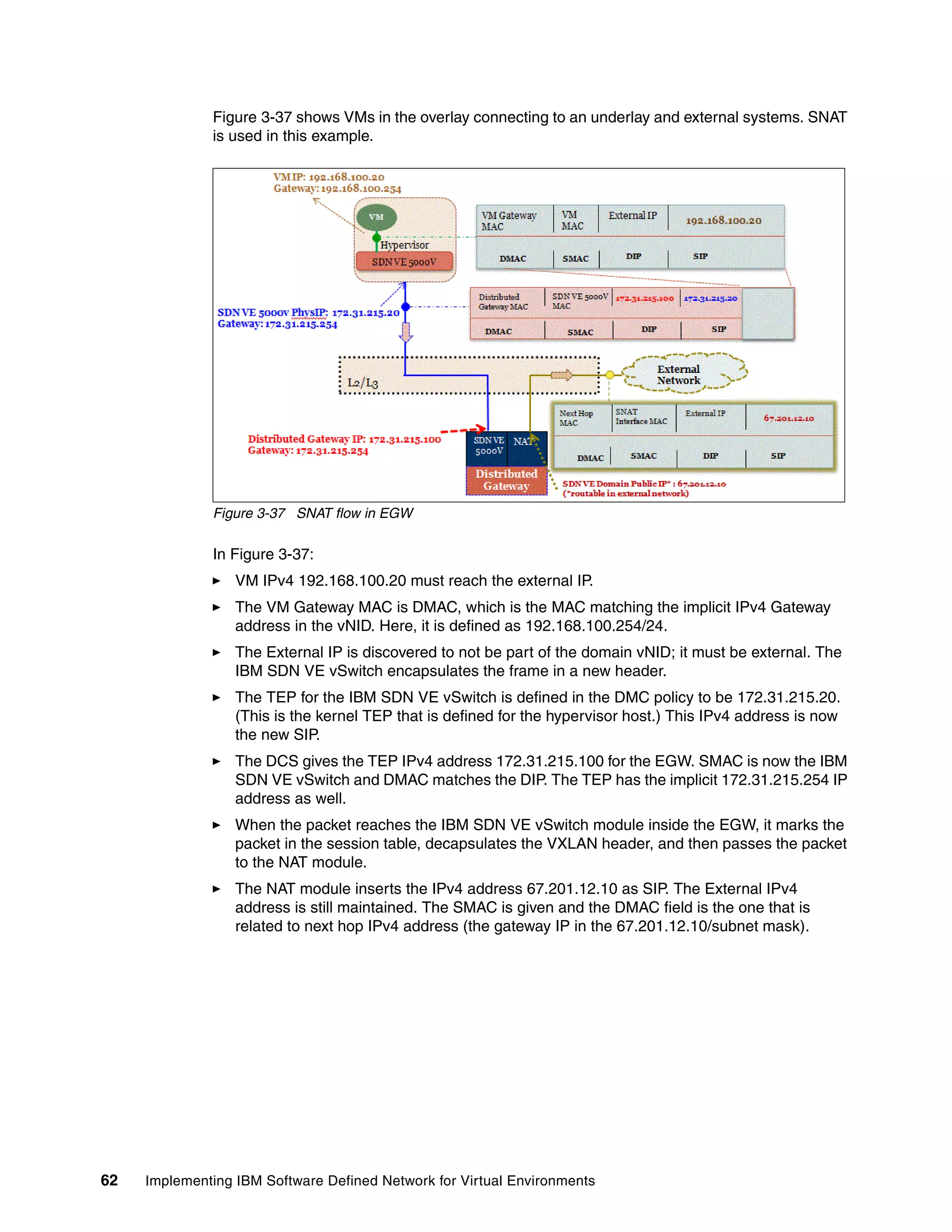
Figure 3-19 shows DCS roles that are assigned for IP addresses 9.70.42.161 - 163.
Figure 3-19 A configuration with three DCSs
The following section explains how the DCS functions as a cluster and how replication works.
It also explains how the DCS controls policies and how it disseminates policies and the
purpose of the field config version in Figure 3-19.
3.3.1 Distributed Connectivity Service cluster formation
This section describes how a DCS cluster is formed. Initially, the DMC’s database is not
populated with DCS information and the DMC has no information about the DCS and its
members. DMC just has registration of DSA and its capabilities (for example, DCS or DGW).
All DSAs have a “CS Role Assigned [N] “from initial setup or start of the setup, as shown in
Figure 3-19.
When the DCS is defined in the DMC as “CS Role Assigned [Y]”, it is synchronized by the
DMC and the database is populated with this information. The DCS member that is recently
assigned for connectivity service requests information from other DCSs in the system from
the DMC. The message exchange is shown in Figure 3-20 on page 47. This is how all DCSs
discover other DCS members in the system.](https://image.slidesharecdn.com/sg248203-150917153659-lva1-app6892/75/Sg248203-62-2048.jpg)


![Chapter 3. Introduction to IBM Software Defined Network for Virtual Environments components 69
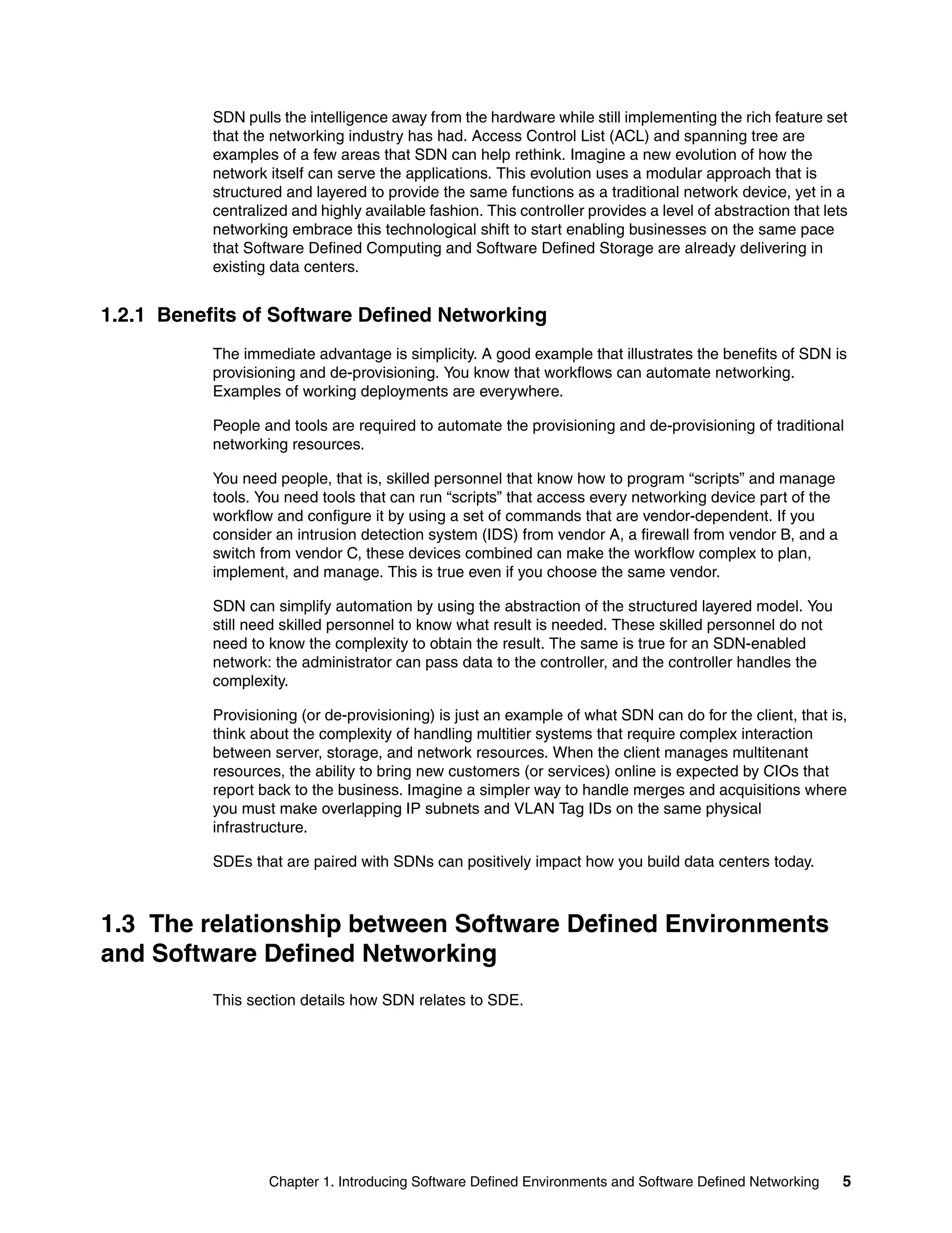
3.7.3 IBM SDN VE vSwitch user module
This module is responsible for IBM SDN VE vSwitch communications between external
agents, such as DMC, DCS, and the IBM SDN VE vSwitch kernel module. The user module
has a local database to store policies, multicast database, location information, and other
information. When the kernel module misses a lookup for data that is handled by its database,
it queries the user module database for the resolution. The database is populated by
interacting with DCS. It supports REST- and TLV-based protocols.
3.7.4 Encapsulation
The IBM SDN VE vSwitch is deployed near endpoints, so it can intercept traffic that originates
in these endpoints and deliver it to them. Because the IBM SDN VE environment spans the IP
network, it uses tunnel encapsulation for packets to send the packets over the IP network.
This encapsulation consists of an IP header and a UDP header followed by a VxLAN header.
3.7.5 Supported protocols
The IBM SDN VE vSwitch supports ARP, DHCP, ICMP, and IGMP. Any other packet is
dropped on receipt.
It supports IGMPv2, ICMP processing, ping processing, and ARP processing.
3.7.6 Communication with other modules
The IBM SDN VE vSwitch communicates with two external entities: the DCS and the DMC.
Host module communication with the DCS is mainly for policy resolution, Multicast Group
Information, Location Information, and so on, and is orchestrated through the DOVE Agent.
DPA communicates with the DMC to get configuration information, send logging information,
and so on.
The IBM SDN VE vSwitch communicates with the DMC to accomplish the following tasks:
Provides VM and port statistics information periodically, and demand-based information to
the controller
Provides log information on demand to the controller
Gets DPS server configuration information from the controller
The IBM SDN VE vSwitch communicates with the DCS to accomplish the following tasks:
Endpoint location query
Policy lookup
Endpoint update [add/invalidate]
Gateway/ARP resolution
The IBM SDN VE vSwitch communicates with the 5000V to accomplish the following tasks:
Provides VM/port statistics information periodically, and provides demand-based
information to the controller
Provide log information on demand to the controller](https://image.slidesharecdn.com/sg248203-150917153659-lva1-app6892/75/Sg248203-85-2048.jpg)


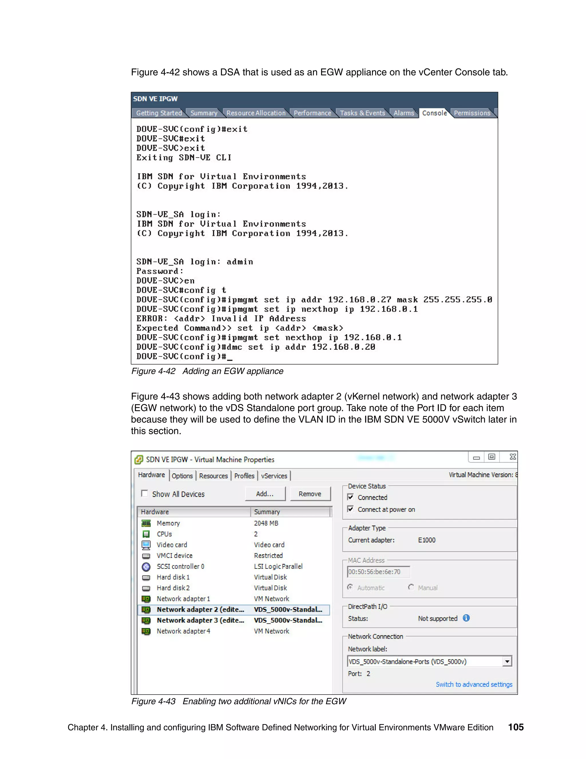
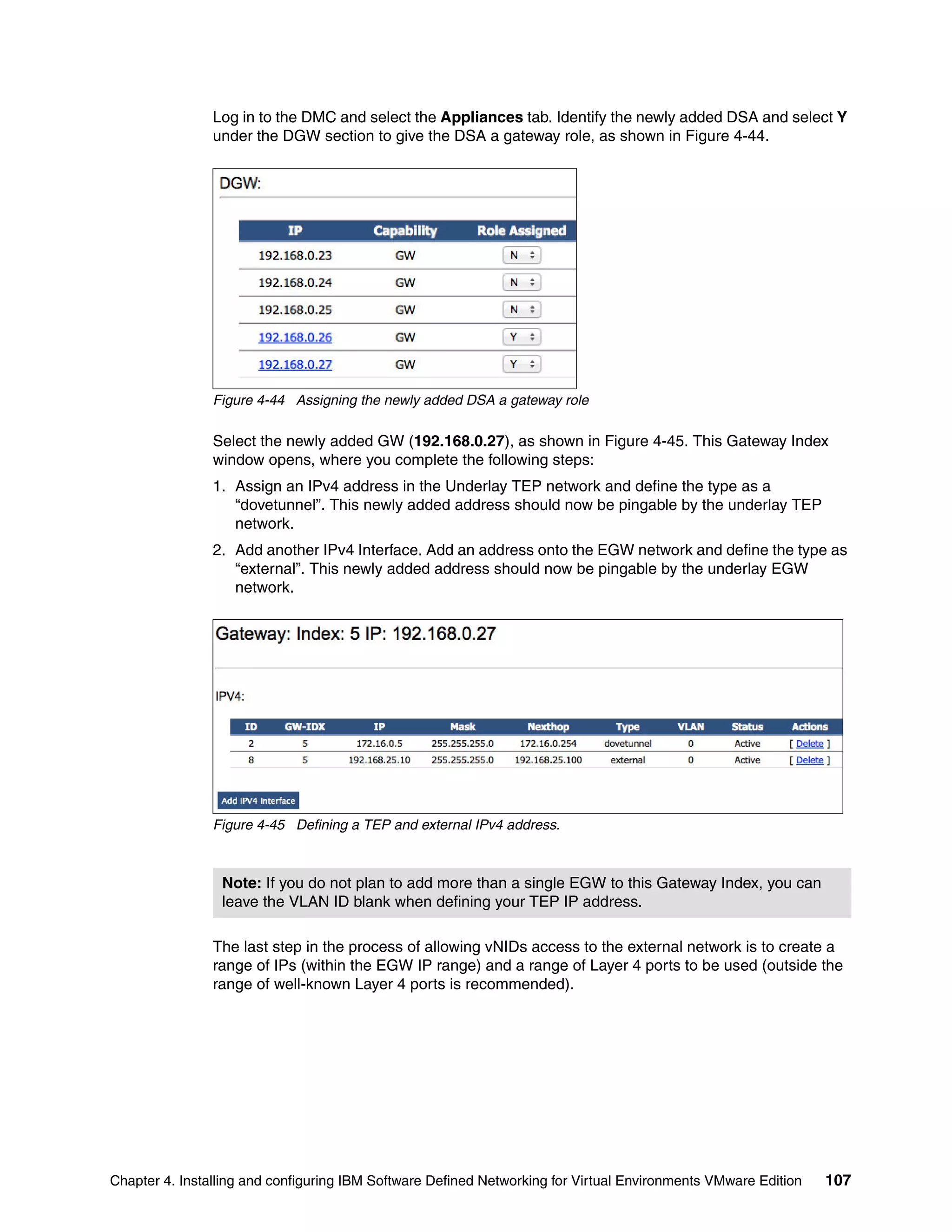
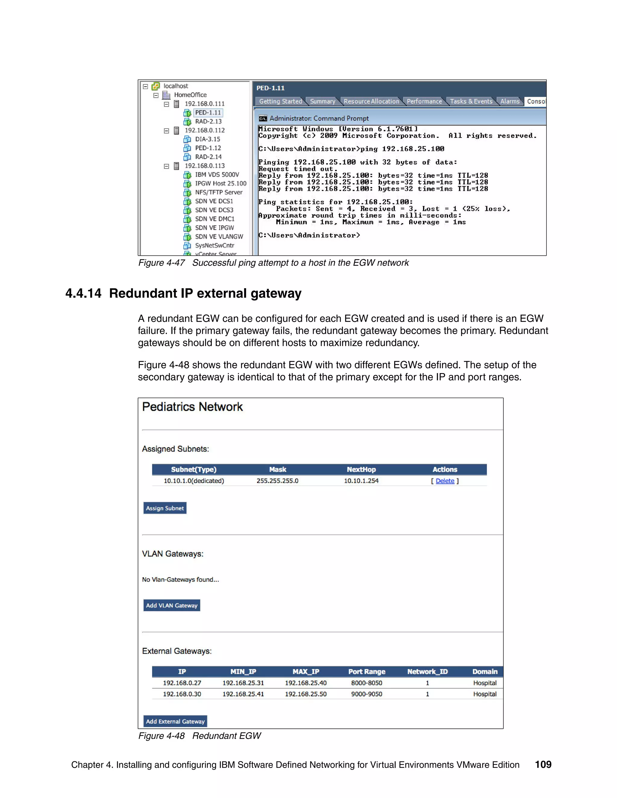
![Chapter 4. Installing and configuring IBM Software Defined Networking for Virtual Environments VMware Edition 89
Example 4-3 IBM SDN VE 5000V vSwitch initial configuration
5000V# configure terminal
5000V(config)# interface ip-mgmt address 192.168.0.28 255.255.255.0 192.168.0.1
5000V(config)# interface ip-mgmt gateway enable
5000V(config)# ssh enable
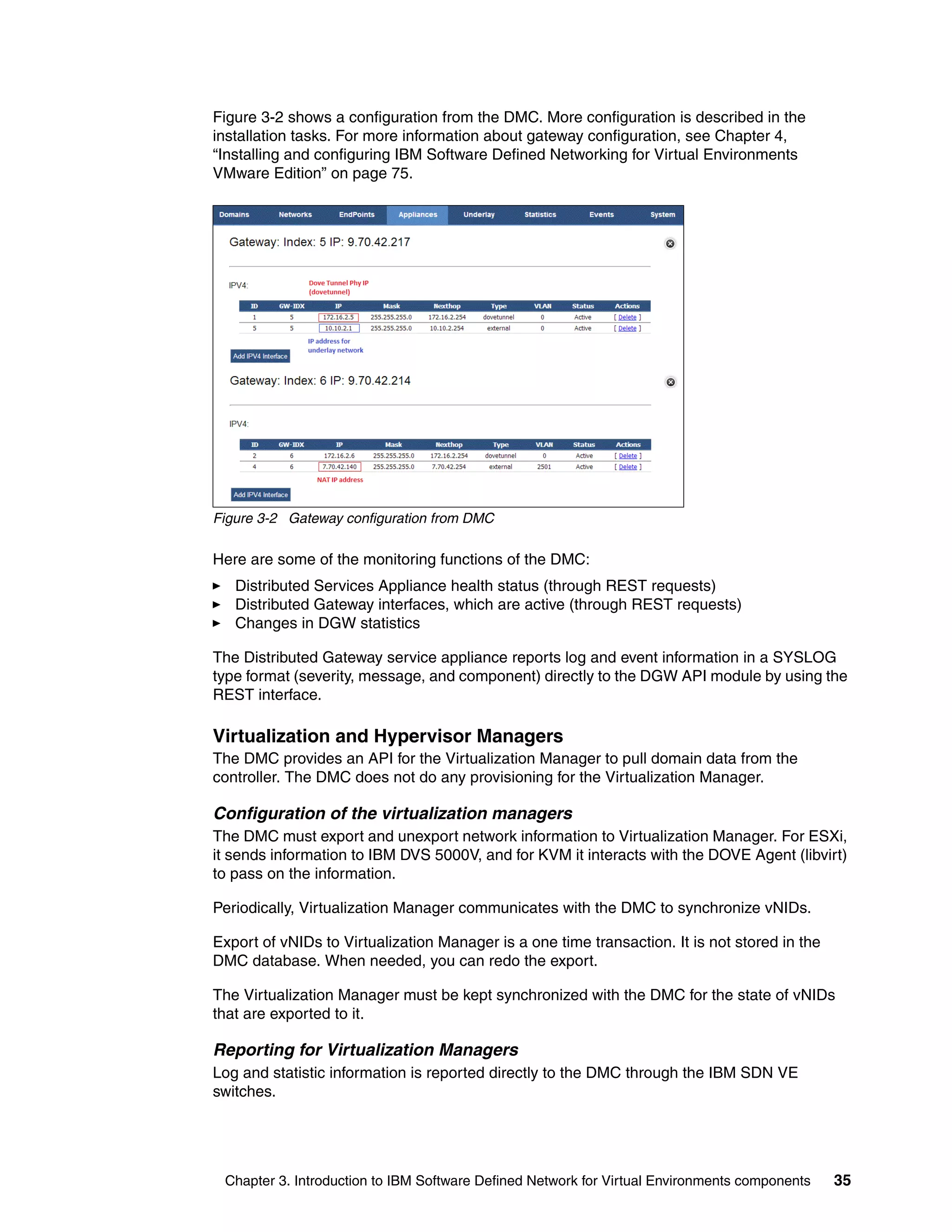
3. Connect the IBM SDN VE 5000V vSwitch to vCenter and create the vDS vSwitch. Point
the IBM SDN VE 5000V vSwitch to the DMC cluster address and save the configuration.
Example 4-4 shows the commands that you run to accomplish these tasks.
Example 4-4 IBM SDN VE 5000V vSwitch connectivity to vCenter and DMC
5000V# configure terminal
5000V(config)# iswitch vcenter 192.168.0.100 root [press the enter key]
5000V(config)# iswitch vds VDS_5000v HomeOffice
5000V(config)# iswitch dmc 192.168.0.20
5000V(config)# copy run start
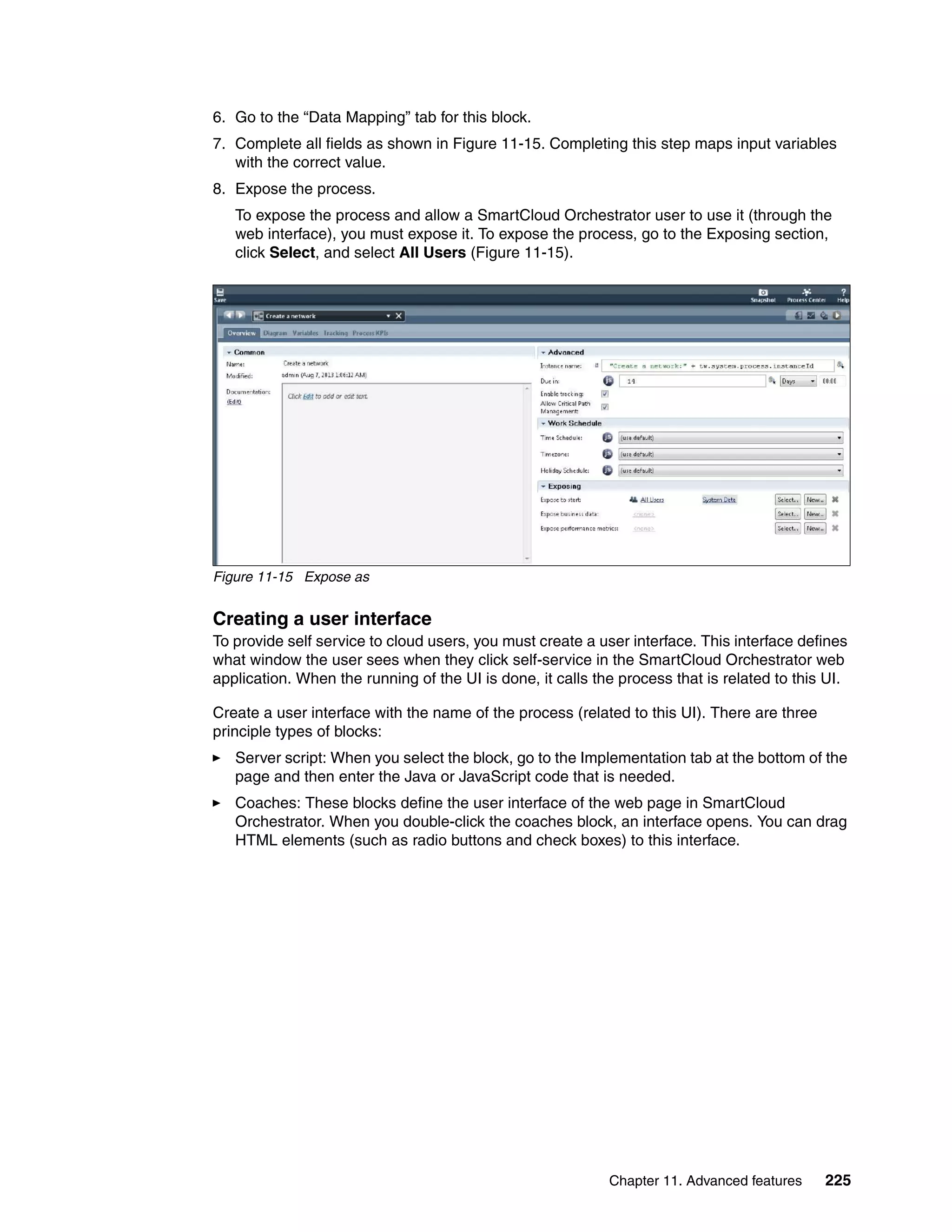
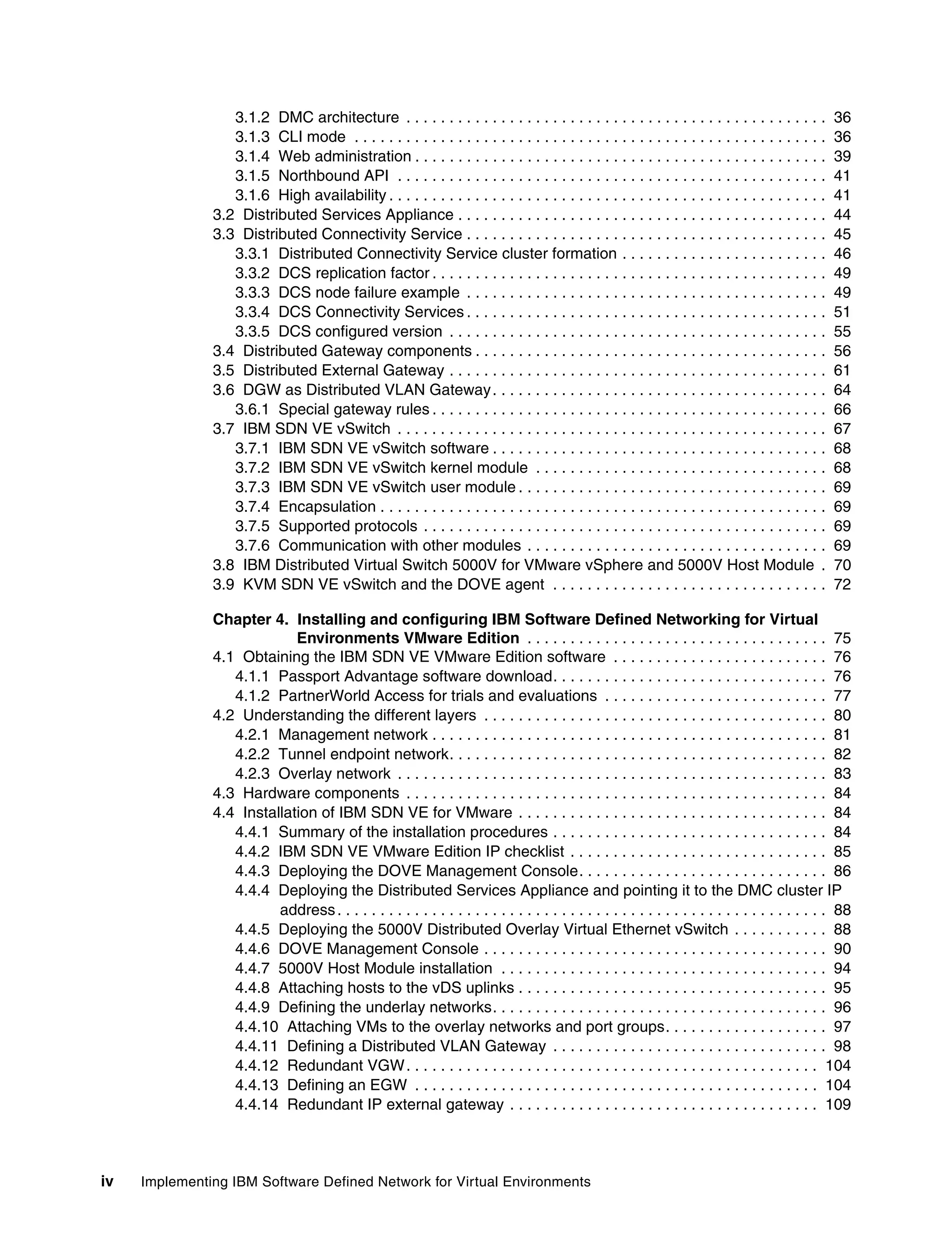
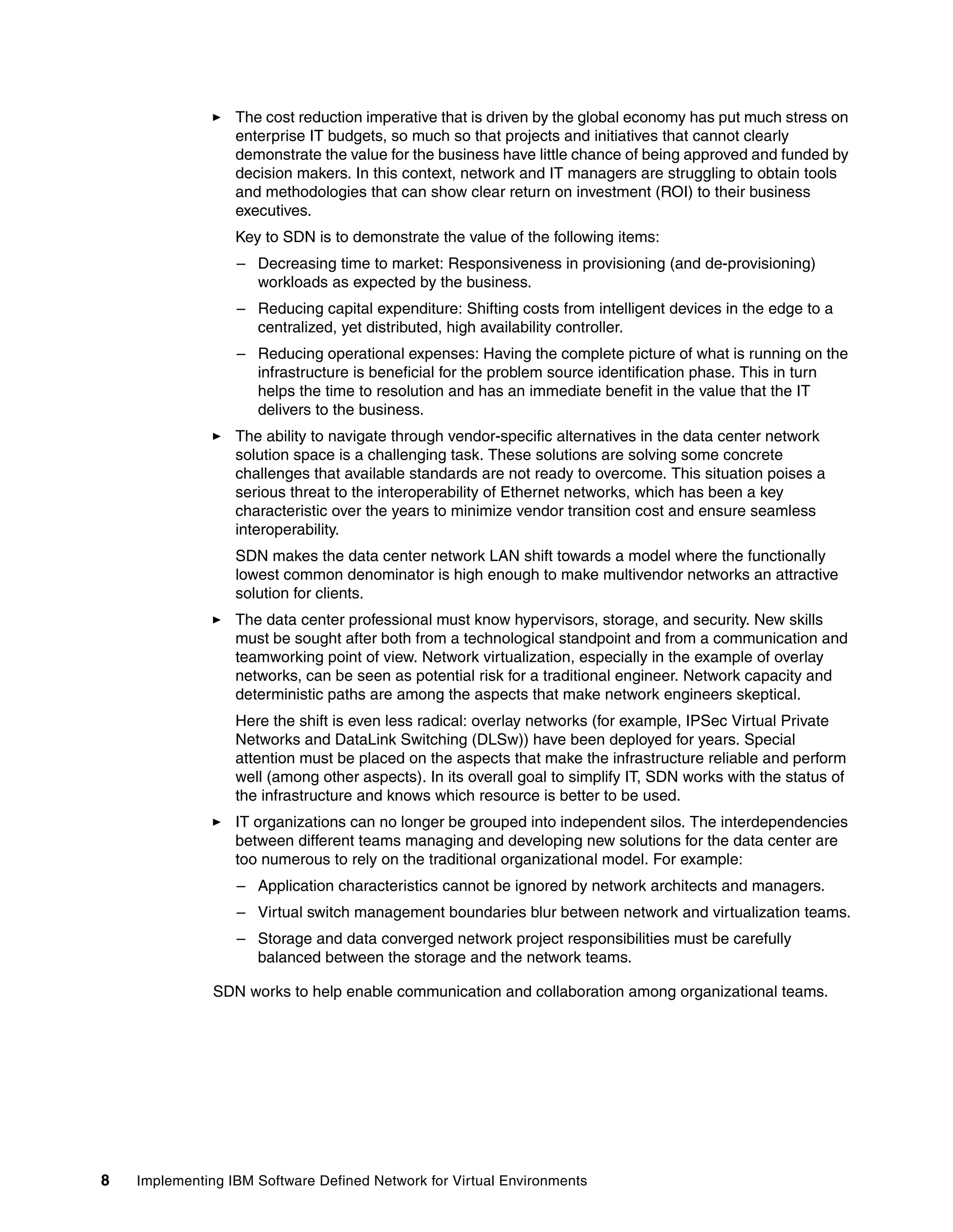
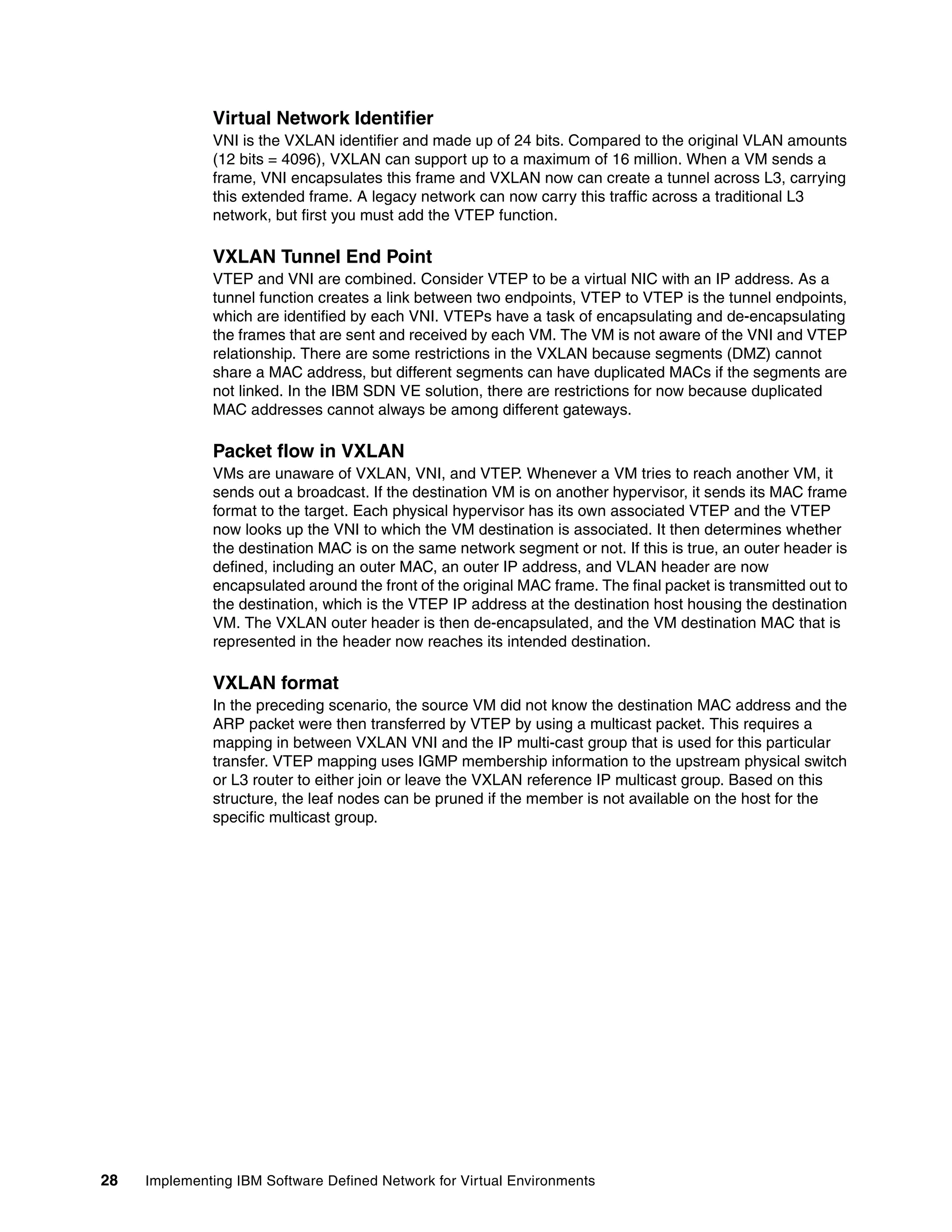
Figure 4-19 shows vCenter networking after the VDS_5000v switch is deployed to vCenter.
Figure 4-19 vCenter networking
The following port groups are created in vCenter:
~Standard-Ports
~Uplink-Defaults
~DS-IP-ADDR-PROF
Note: No other configuration of the VDS 5000V switch is necessary until later in this
chapter (that is, defining the VLAN and EGWs).](https://image.slidesharecdn.com/sg248203-150917153659-lva1-app6892/75/Sg248203-105-2048.jpg)


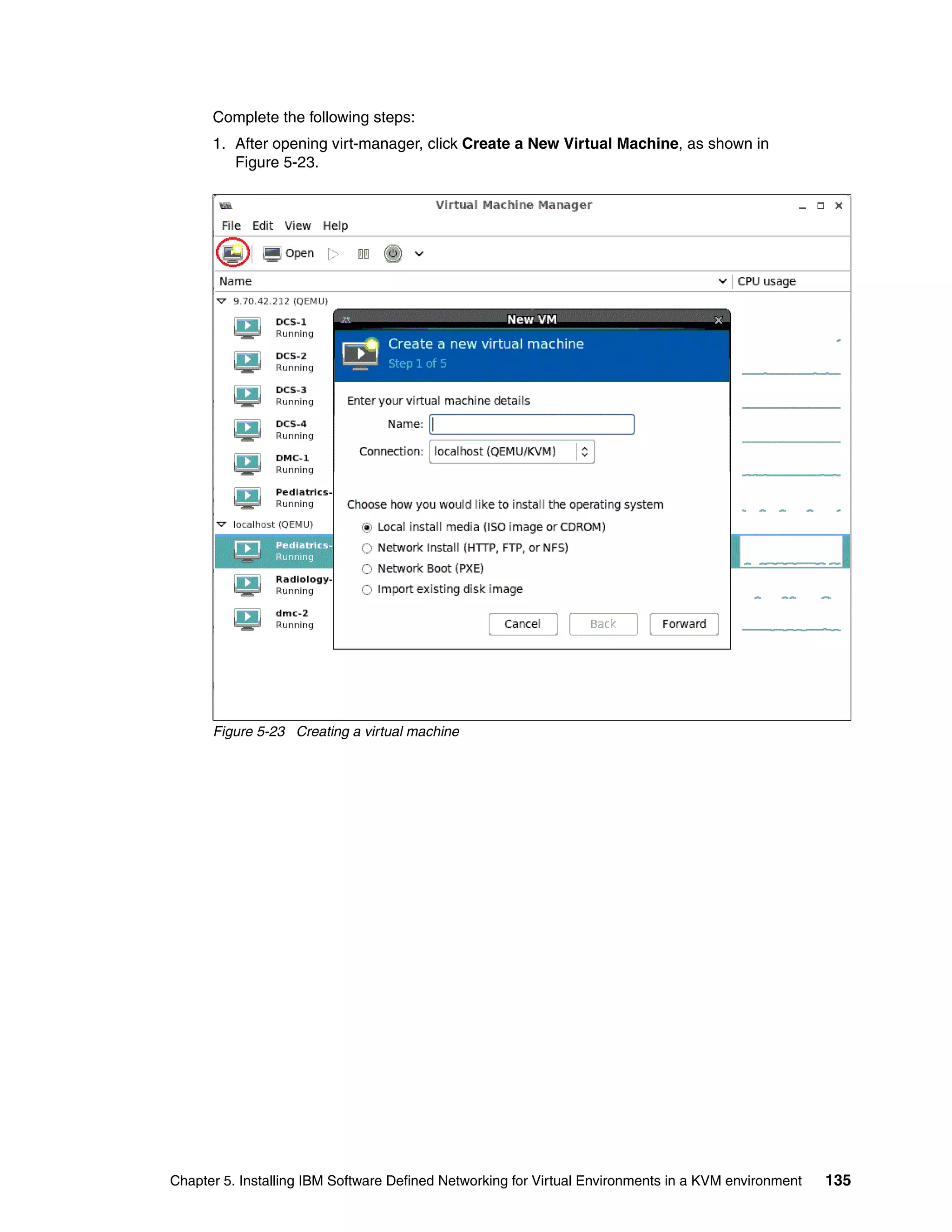
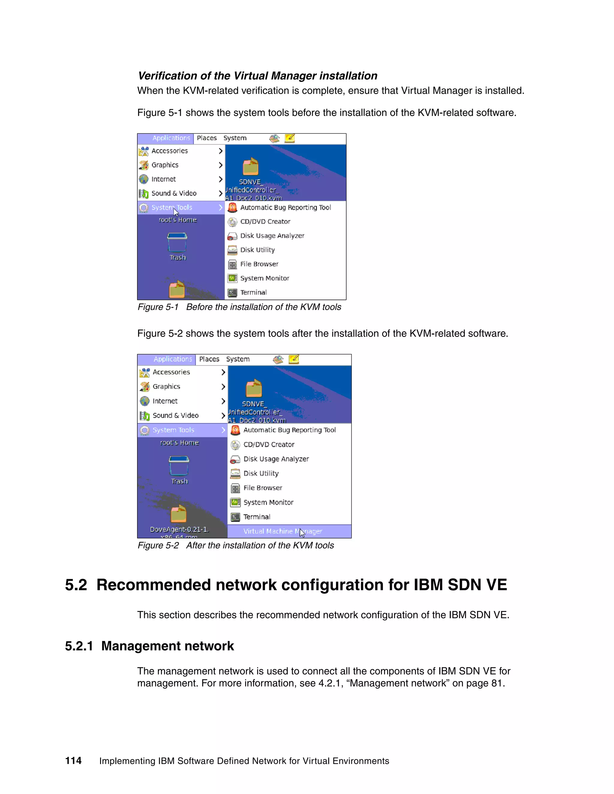
![Chapter 5. Installing IBM Software Defined Networking for Virtual Environments in a KVM environment 113
Loading the KVM module
After the installation of the KVM-related packages, load the KVM modules by running the
following command:
modprobe kvm
Insert the chip-specific KVM modules by running the following commands:
modprobe kvm-intel
modprove kvm-amd
Verify that the module is inserted by running the following command:
lsmod | grep kvm
The output is shown in Example 5-4.
Example 5-4 Command to check whether the module is loaded
[root@sdn-kvm-1 ~]# lsmod | grep kvm
kvm_intel 54157 18
kvm 332884 1 kvm_intel
Starting the libvirt daemon
Run the following command to start the libvirtd daemon:
service libvirtd start
Example 5-5 shows an example of the output of this command.
Example 5-5 Output of libvirtd start
[root@sdn-kvm-1 ~]# service libvirtd start
Starting libvirtd daemon: [ OK ]
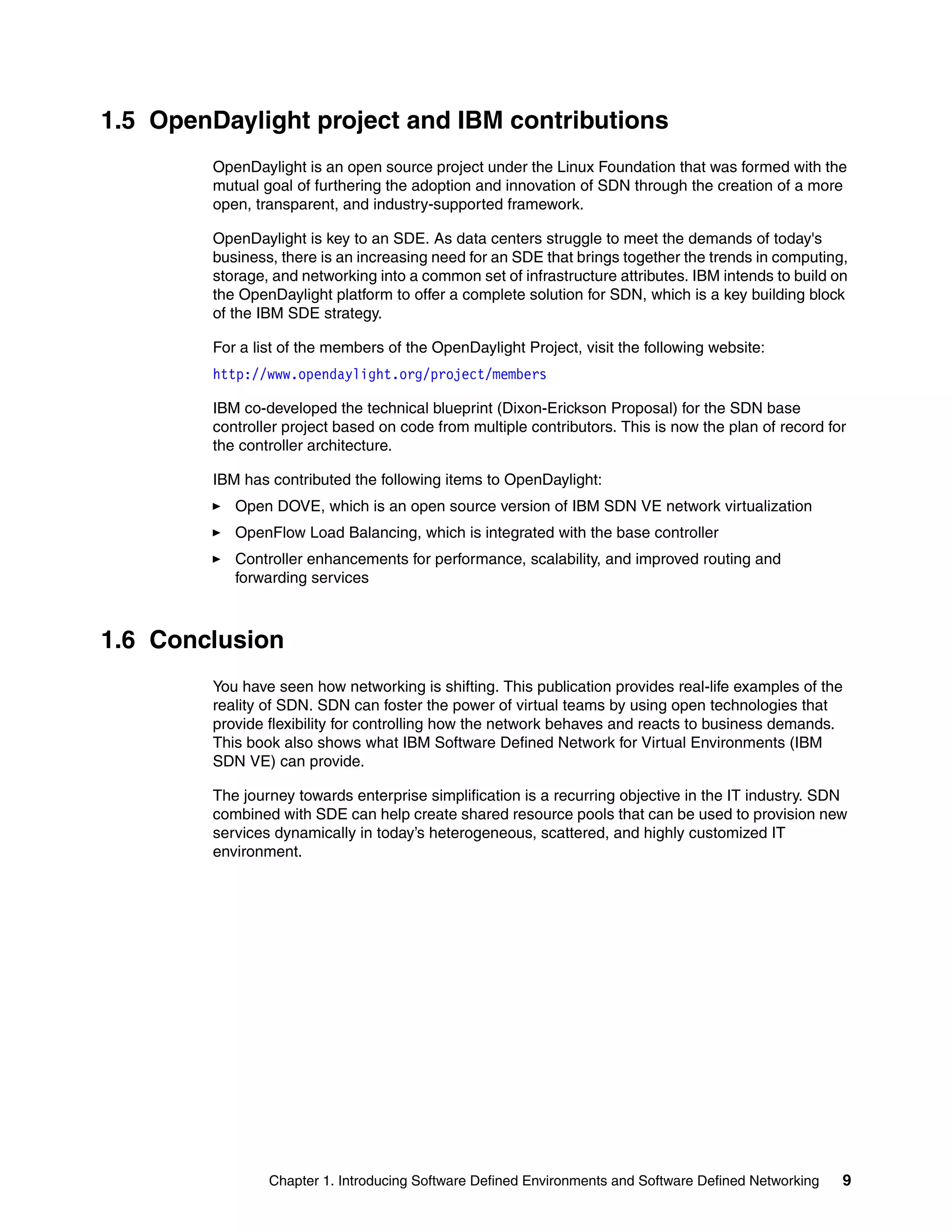
Verifying the default network
To verify that the virtual default network is created, run the following command:
ifconfig virbr0
This default virtual network comes with an isolated virtual bridge device, virbr0, which is set to
the 192.168.122.x subnet by default. The host is assigned the 192.168.122.1 address. You
can assign an address to your guest VM from this subnet by manually setting up your network
during or after operating system installation. This device is shown in Example 5-6.
Example 5-6 Output of ifconfig virbr0
[root@sdn-kvm-1 ~]# ifconfig virbr0
virbr0 Link encap:Ethernet HWaddr 52:54:00:34:9A:58
inet addr:192.168.122.1 Bcast:192.168.122.255 Mask:255.255.255.0
UP BROADCAST RUNNING MULTICAST MTU:1500 Metric:1
RX packets:0 errors:0 dropped:0 overruns:0 frame:0
TX packets:0 errors:0 dropped:0 overruns:0 carrier:0
collisions:0 txqueuelen:0
RX bytes:0 (0.0 b) TX bytes:0 (0.0 b)
When all the preceding steps are verified, the KVM-related software is ready to be used.](https://image.slidesharecdn.com/sg248203-150917153659-lva1-app6892/75/Sg248203-129-2048.jpg)
![Chapter 5. Installing IBM Software Defined Networking for Virtual Environments in a KVM environment 115
5.2.2 Data network
The data network is used to configure the tunnel endpoint, which is used to connect host
modules and gateways. For more information, see 4.2.2, “Tunnel endpoint network” on
page 82.
5.2.3 EXT network
This is the network that is used to connect to the outside network using network address
translation (NAT) functions, and so on. For more information, see 4.2.3, “Overlay network” on
page 83.
5.3 Installation of the Unified Controller
This section covers installation of the Unified Controller.
5.3.1 Images for the Unified Controller
Download the image, which is in the .kvm format, from the IBM website. The image has a
name similar to SDNVE_UnifiedController_GA1_Dpc2_001.kvm.
The software can be downloaded from Passport Advantage. For more information, see 4.1,
“Obtaining the IBM SDN VE VMware Edition software” on page 76.
Extract the image and store the contents on the host where you want to deploy the DMC in
the /var/lib/libvirt/images path. The commands to extract the image and copy it are
shown in Example 5-7.
Example 5-7 Commands to extract and copy
[root@sdn-kvm-1 Desktop]# tar -xvf SDNVE_UnifiedController_GA1_Dpc2_010.kvm
ibmDOVE-disk1.qcow2
ibmDOVE-disk2.qcow2
[root@sdn-kvm-1 Desktop]# cp ibmDOVE-disk* /var/lib/libvirt/images/
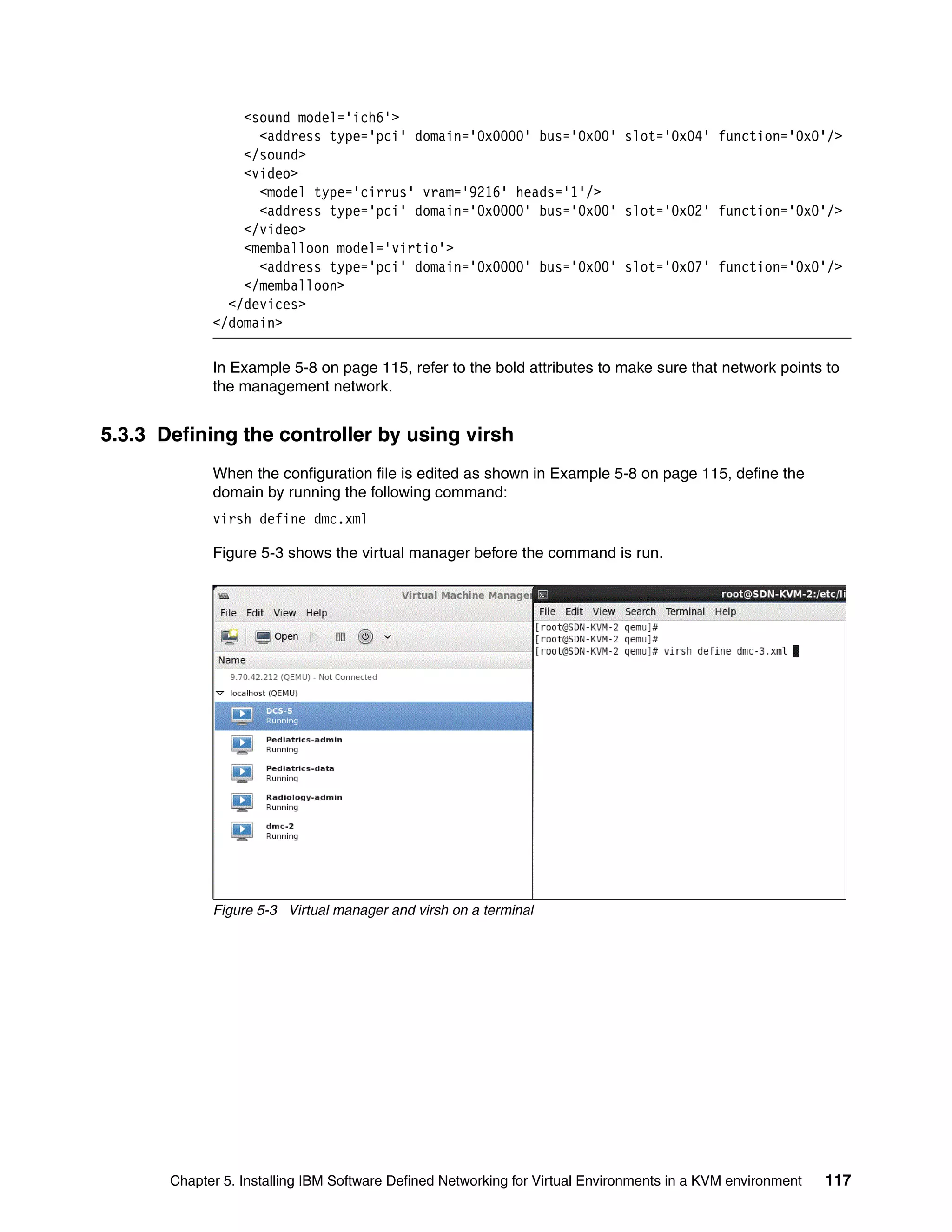
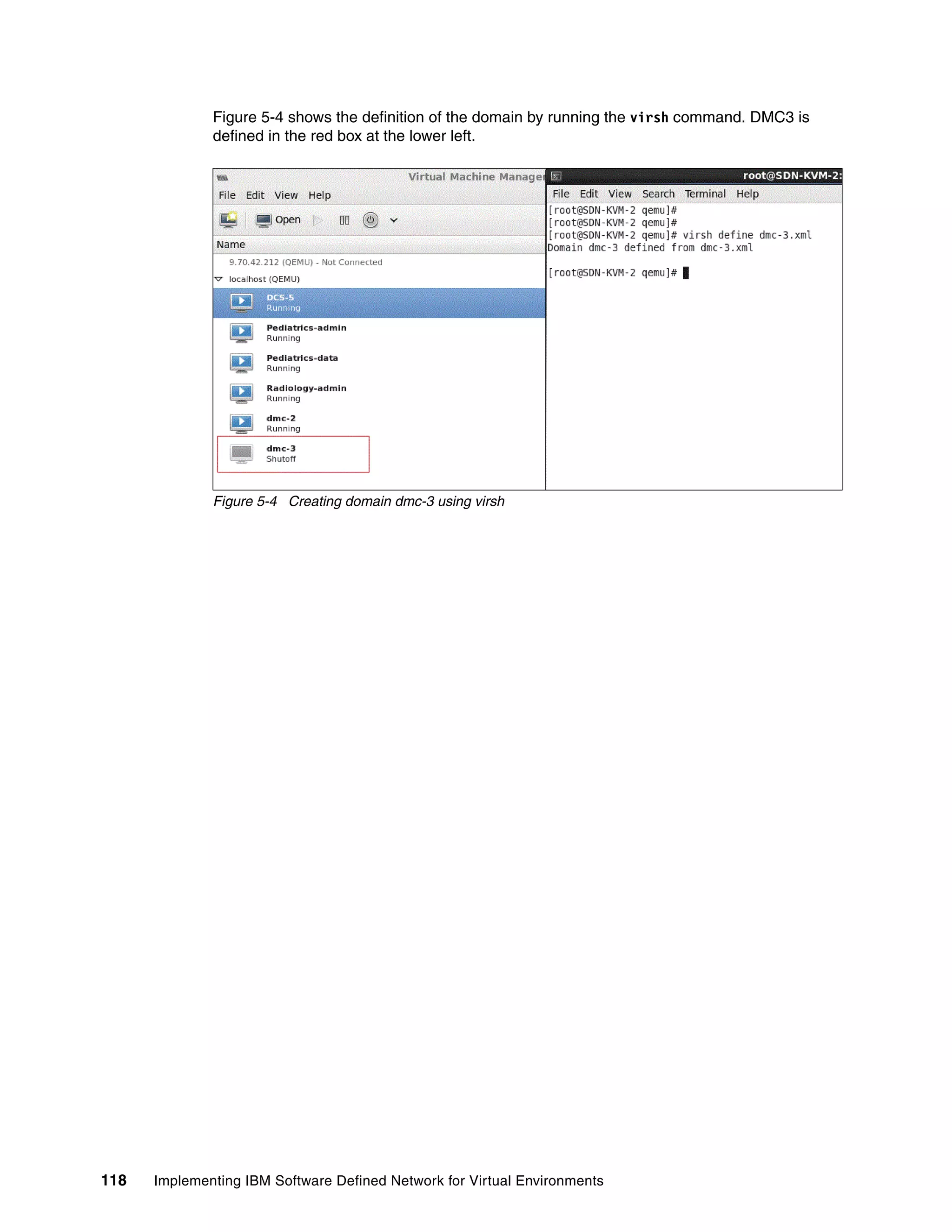
5.3.2 Configuration file that is used to create a virtual machine
Create a configuration file in the /etc/libvirt/qemu directory. An example configuration file is
shown in Example 5-8.
Example 5-8 Example configuration file
<!--
WARNING: THIS IS AN AUTO-GENERATED FILE. CHANGES TO IT ARE LIKELY TO BE
OVERWRITTEN AND LOST. Changes to this xml configuration should be made using:
Note: The file name/image name might change. It is delivered as a file name with the .kvm
extension.
Note: The file name/image name might change at the time of general availability. It is
delivered as a file name with the .qcow2 extension.](https://image.slidesharecdn.com/sg248203-150917153659-lva1-app6892/75/Sg248203-131-2048.jpg)


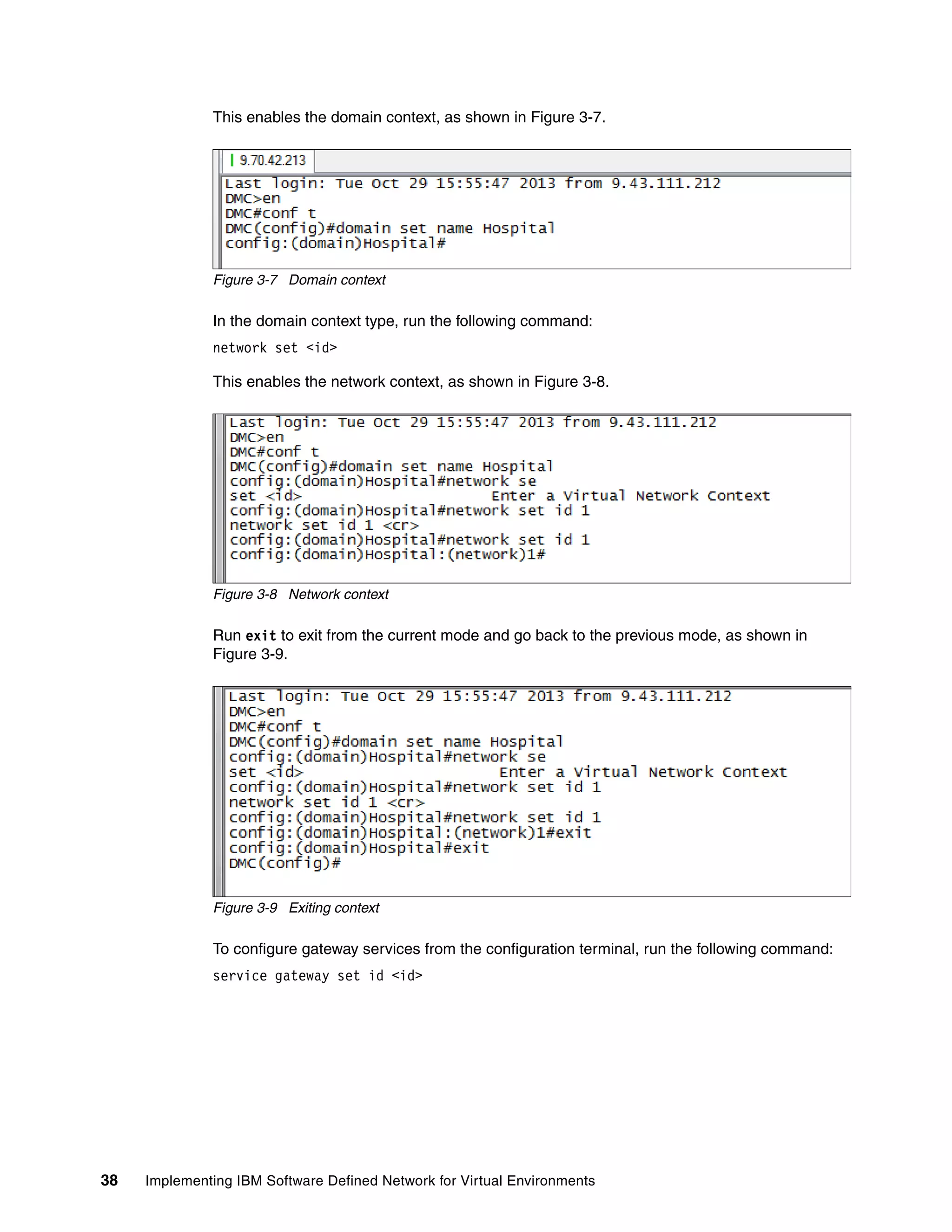
![Chapter 5. Installing IBM Software Defined Networking for Virtual Environments in a KVM environment 125
After the license is accepted and installed properly, your license information can be viewed by
clicking Administration System tools. The successful installation is shown in
Figure 5-12.
Figure 5-12 License acceptance
5.5 Installation of Distributed Services Appliances
This section explains the installation of DSAs.
5.5.1 Images for the Distributed Services Appliance
Download the image, which is in .kvm format, from the IBM website. The image has a name
such as SDNVE_ibmdovesvc.kvm.
Extract the image and store it on the host where you want to deploy the DSA in to the
/var/lib/libvirt/images path. The command to extract the image and copy it are shown in
Example 5-9.
Example 5-9 Extracting the .kvm file and copying its contents
[root@SDN-KVM-2 Desktop]# tar -xvf ibmDOVEsvc.kvm
ibmDOVEsvc-disk1.qcow2
ibmDOVEsvc-disk2.qcow2
[root@SDN-KVM-2 Desktop]# cp ibmDOVEsvc-disk* /var/lib/libvirt/images/
Note: The file name or image name might change. However, it has a file name with the
.kvm extension.](https://image.slidesharecdn.com/sg248203-150917153659-lva1-app6892/75/Sg248203-141-2048.jpg)