Downloaded 17 times


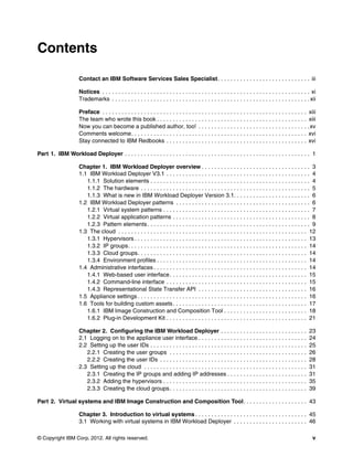
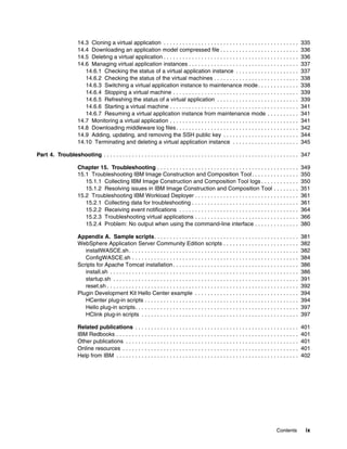


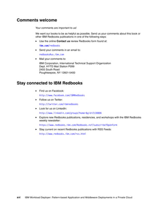

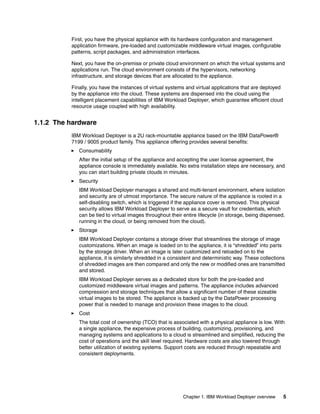
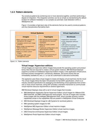
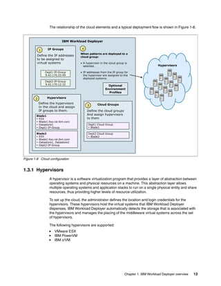
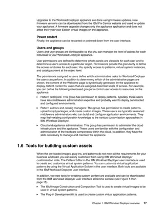
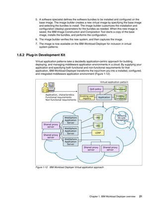
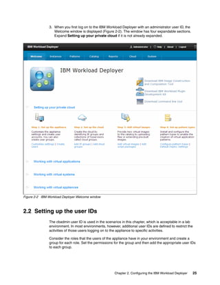
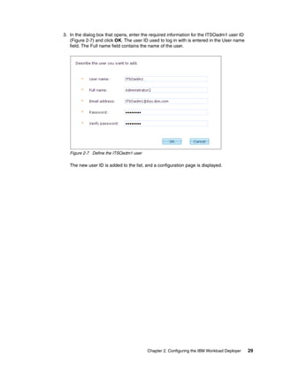
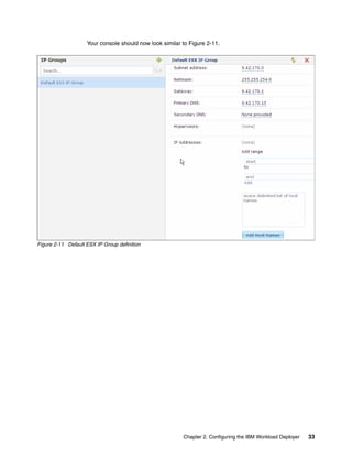
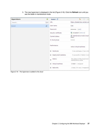
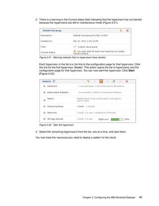


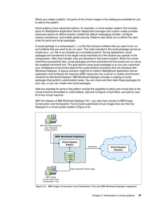
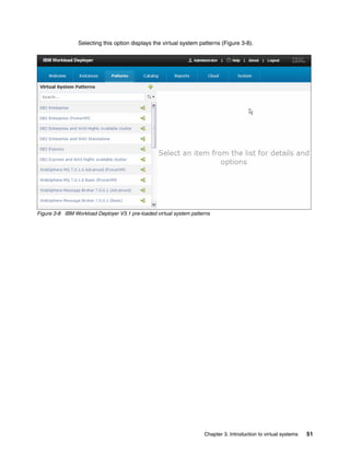
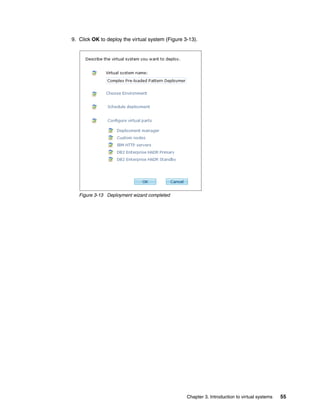
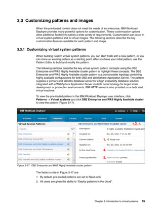
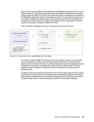
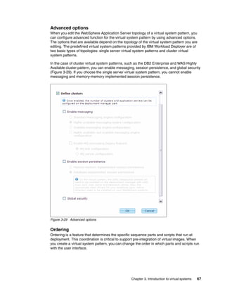
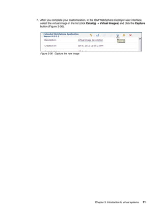

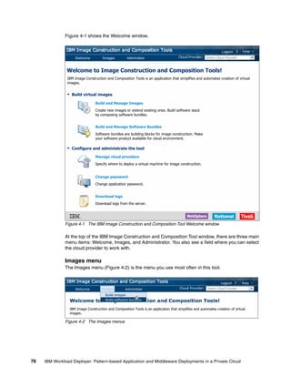
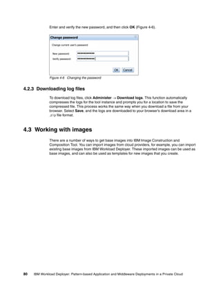
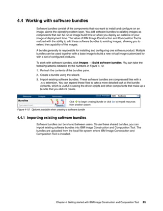
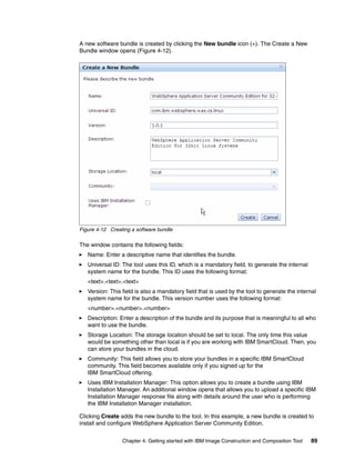
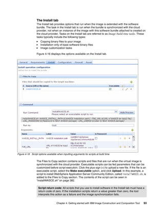
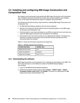
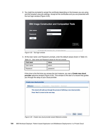
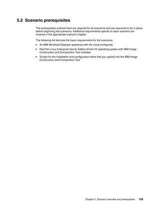
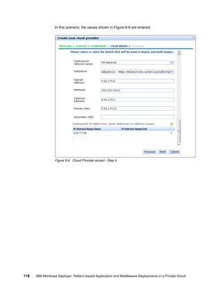
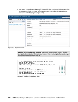
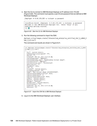
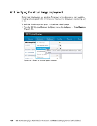
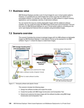
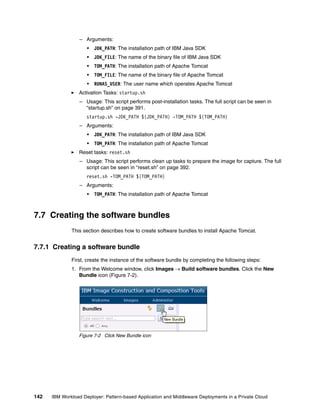
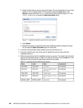
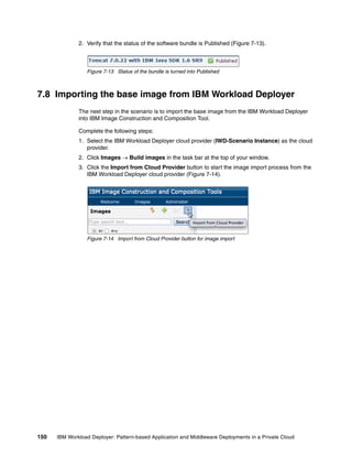
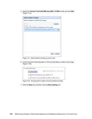
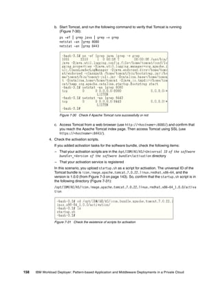
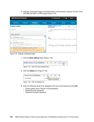
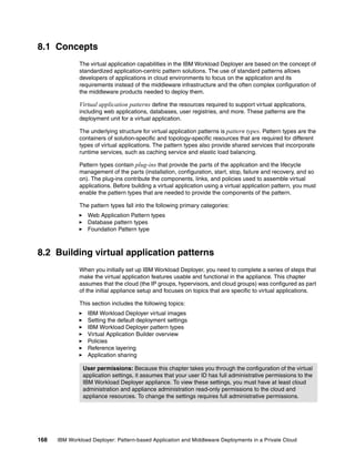
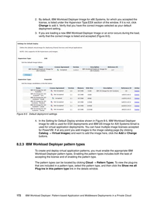
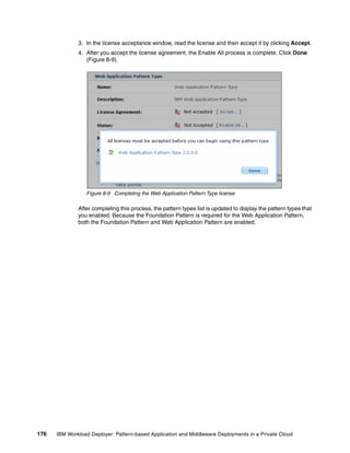
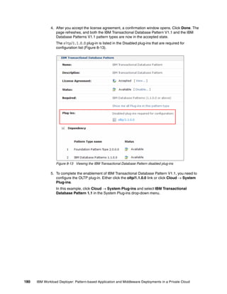
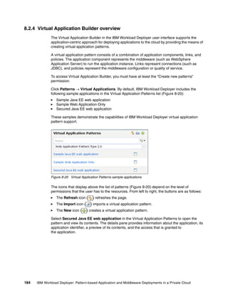
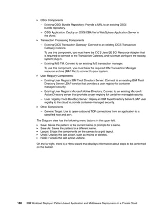
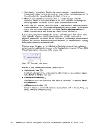
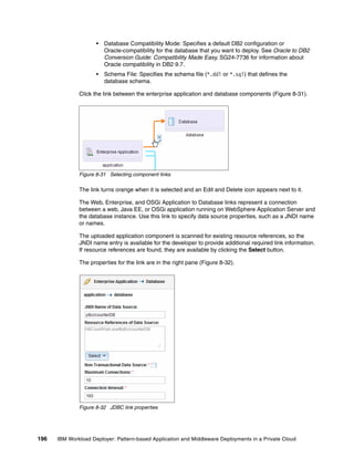
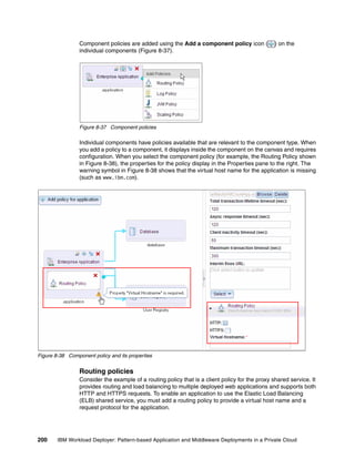
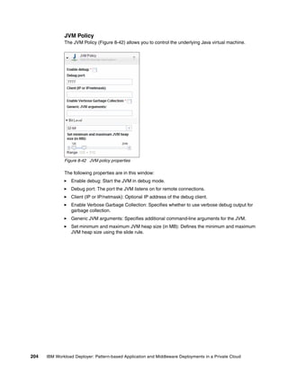
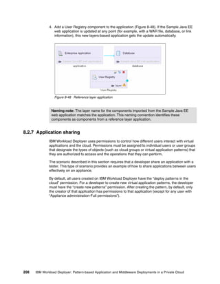
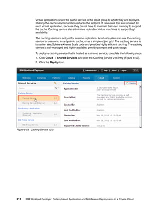
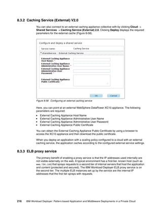
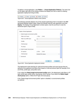
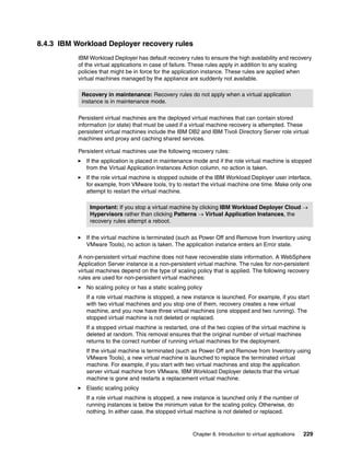
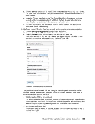
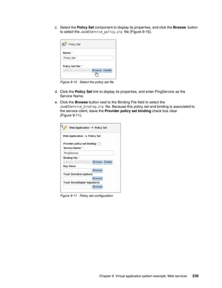
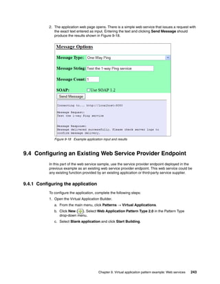
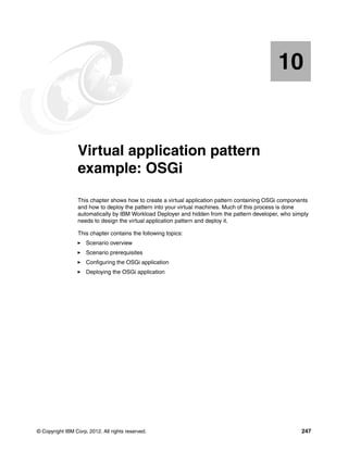
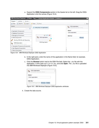
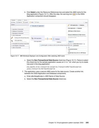
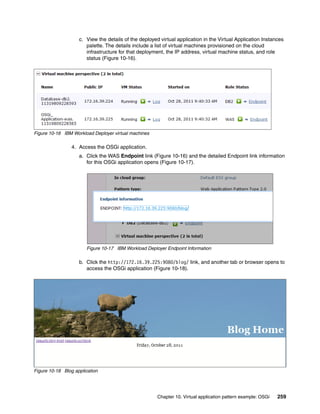
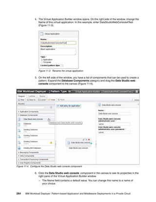
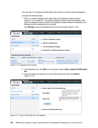
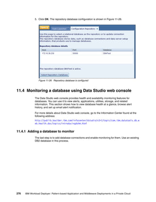
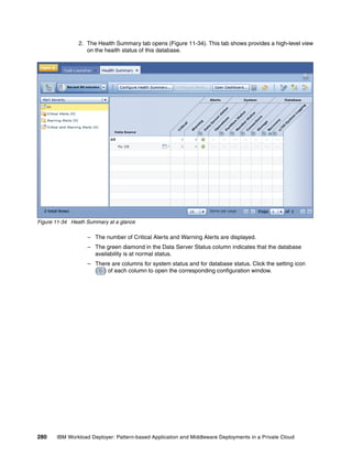
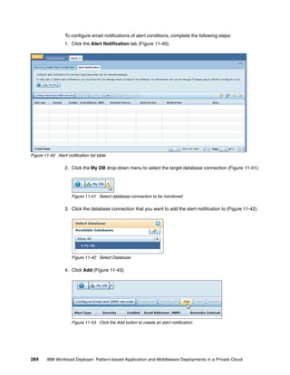
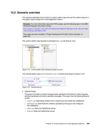
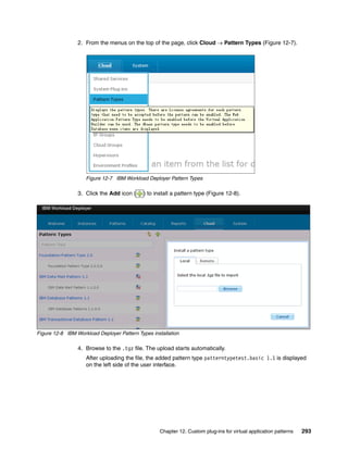
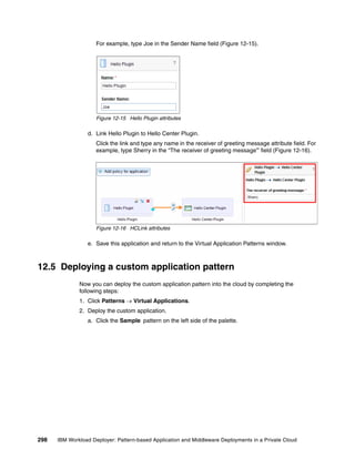
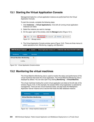
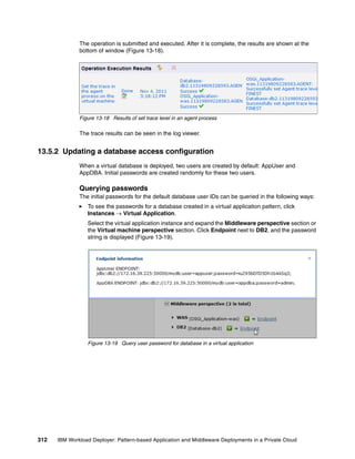
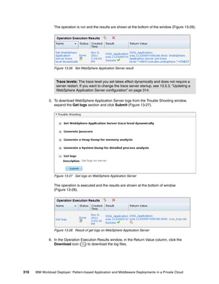
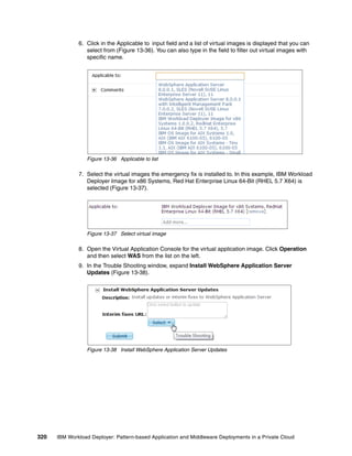
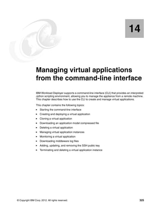
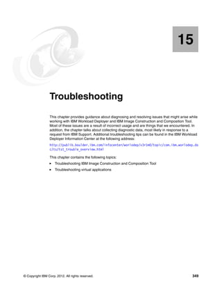
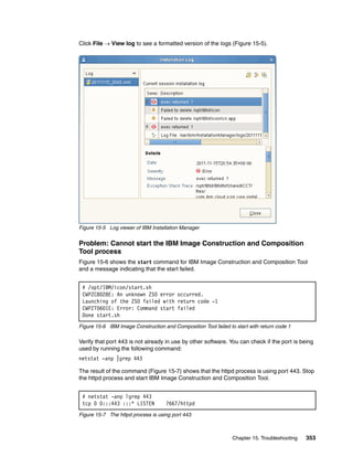
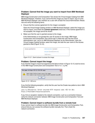
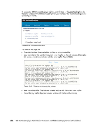
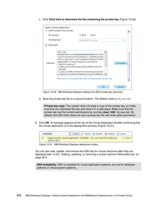
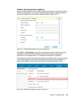
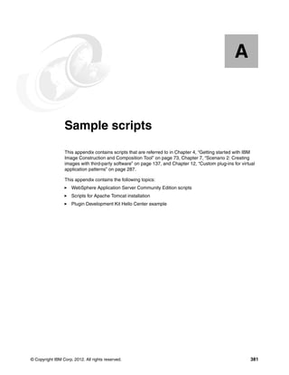
![To edit an image in IBM Image Construction and Composition Tool, click Images Build
images. Select the image and then click the Start Editing icon. You can extend the image by
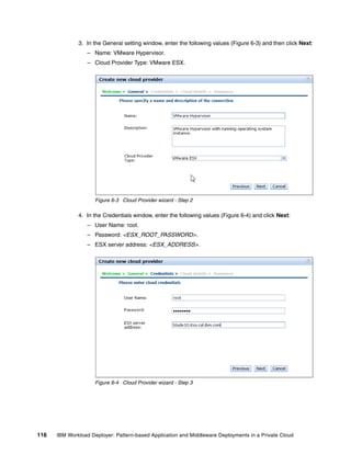
updating the sections shown in Figure 4-9.
Software Bundles:
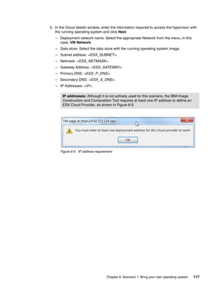
Sort: Alphabetically By install order
Add bundle
Red Hat Enterprise Linux (RHEL) [5.7]
Products:
Red Hat Enterprise Linux Red Hat Enterprise Linux
5.7
(RHEL) (RHEL)
Hardware:
Minimum memory (MB)
2048
Minimum vCPUs
1
Virtual System:
No Virtual System is active at this time
License:
Add License
Figure 4-9 Using the edit option on your virtual image
In Figure 4-9:
Click Add bundle, and select the software bundles to add.
The Products section shows the products that are associated with this image.
You can adjust the minimum memory and the amount of virtual processors that are
associated with this image in this window. When you adjust these values, it is assumed
that sufficient resources are available on the hypervisor where an instance of this image
is deployed.
The license allows you to copy and paste software product licenses that might be required
for your virtual image. These license files are deployed with the instance that is created
from this image.
When an image is deployed for synchronization, a virtual system is created on the cloud
provider. The Virtual System section provides information about the virtual system,
including the IP address.
84 IBM Workload Deployer: Pattern-based Application and Middleware Deployments in a Private Cloud](https://image.slidesharecdn.com/sg248011-121226042448-phpapp02/85/IBM-Workload-Deployer-102-320.jpg)
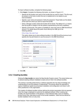
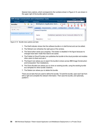
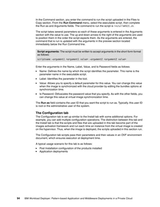

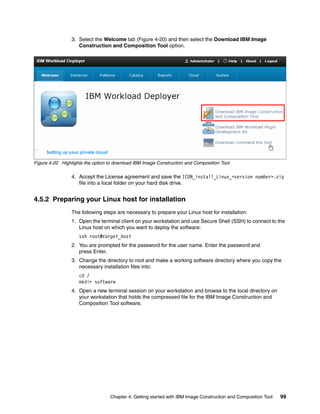
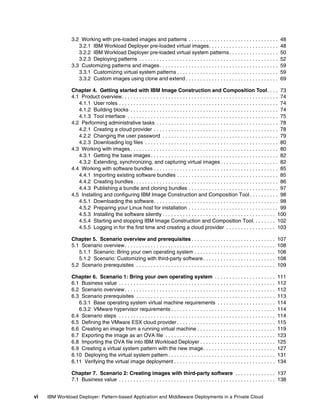
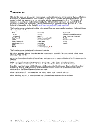
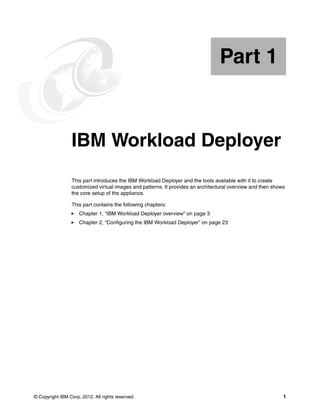
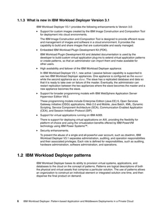
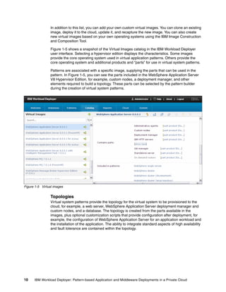
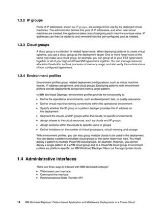
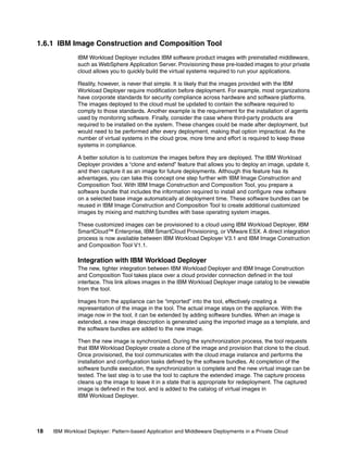
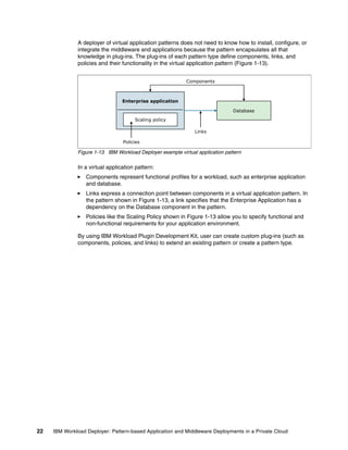
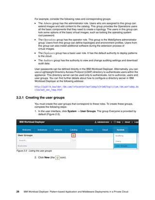
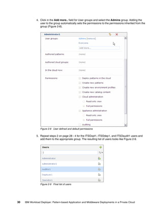
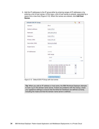
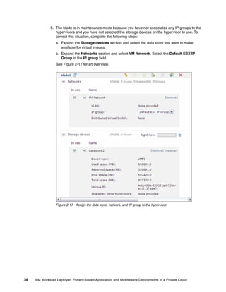
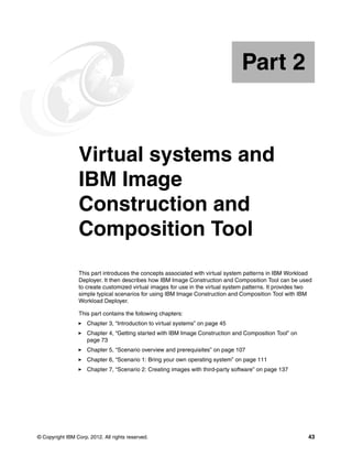
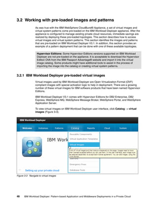
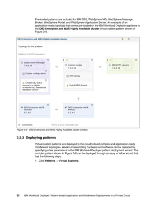
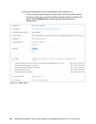
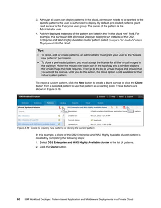
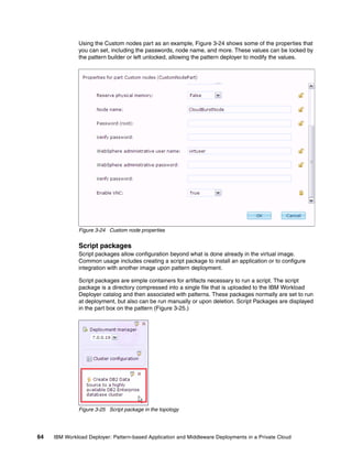
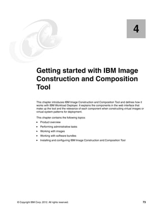
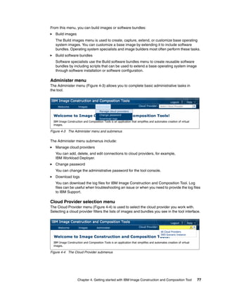
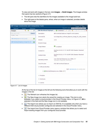
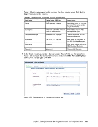
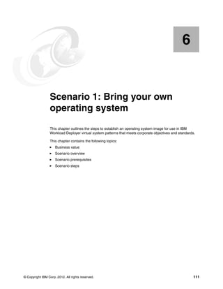
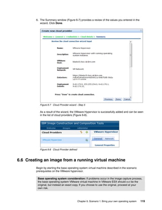
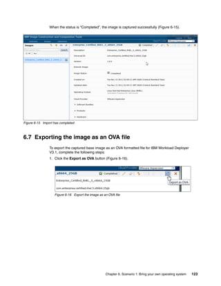
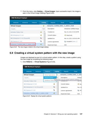
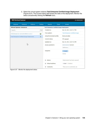
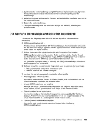
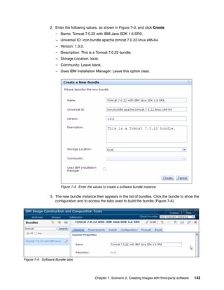
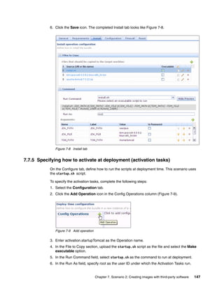
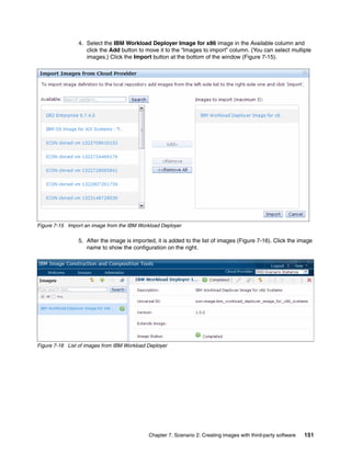
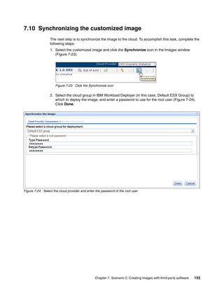
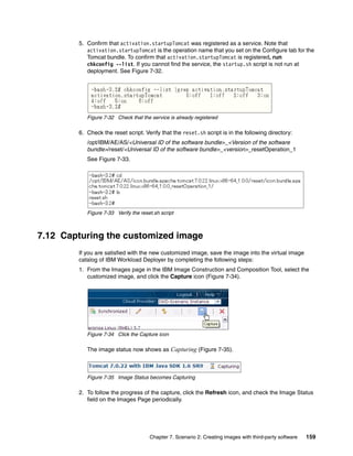
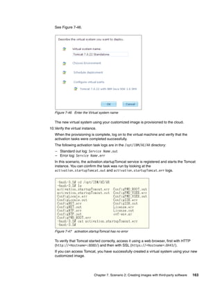
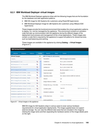
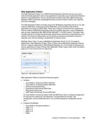
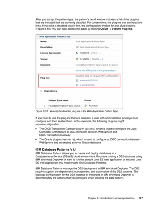
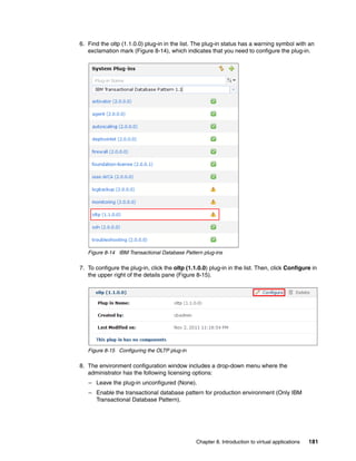
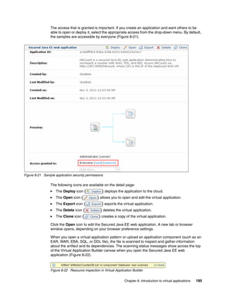
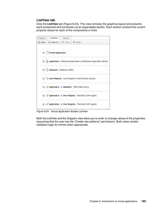
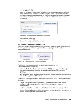
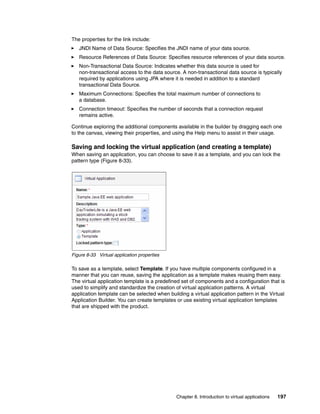
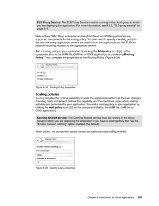
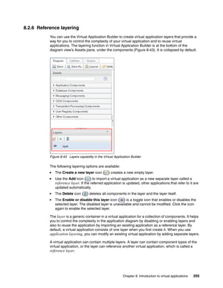
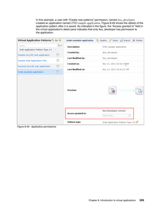
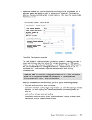
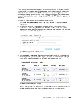
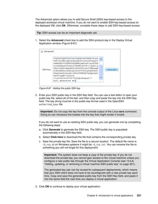
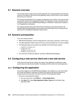
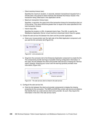
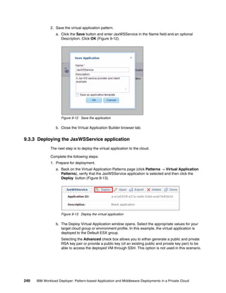
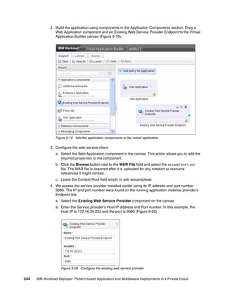
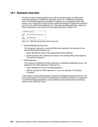
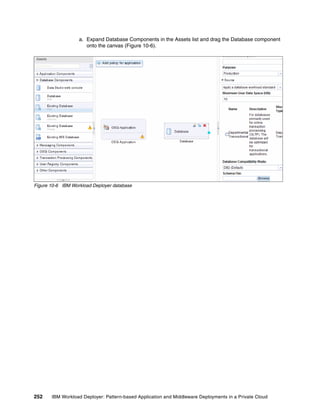
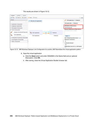
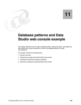
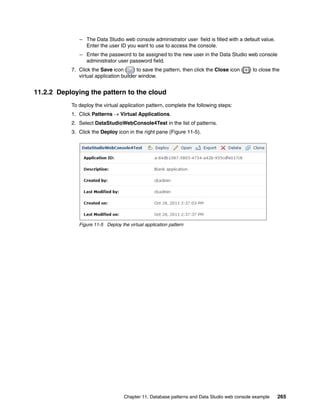
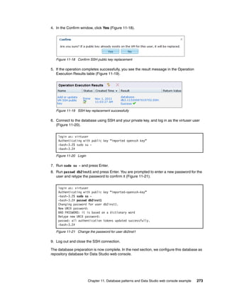
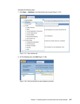
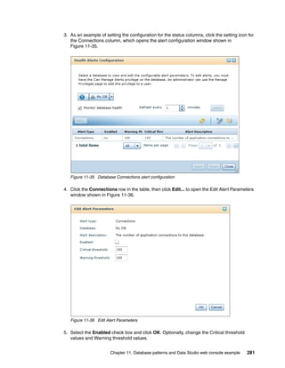
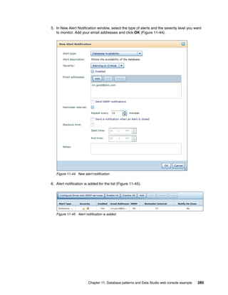
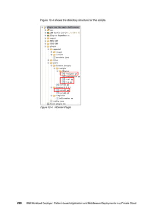
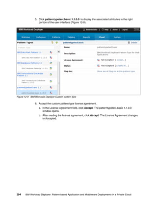
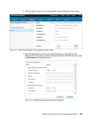
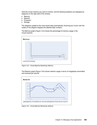
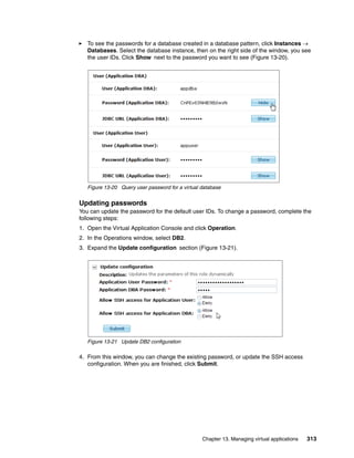
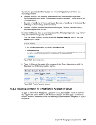
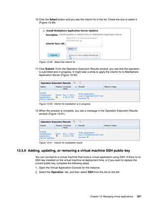
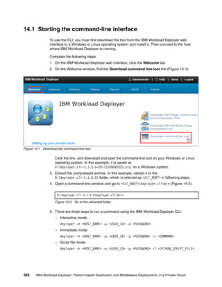
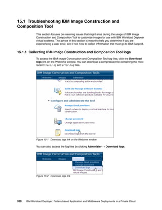
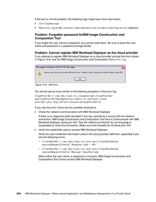
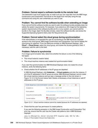
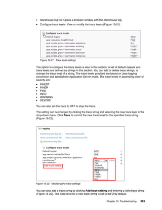
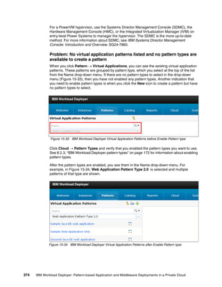
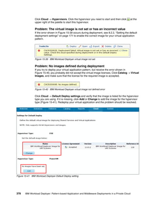
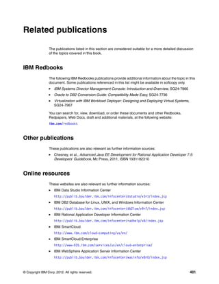
![Figure 4-21 shows the updated file.
Figure 4-21 Copy of edited icon_silent_install_response_file.xml file with changes highlighted in red
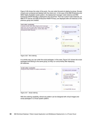
3. After the icon_silent_install_response_file.xml file is edited and saved, run the
following IBM Installation Manager command to perform the installation of the IBM Image
Construction and Composition Tool software:
/opt/IBM/InstallationManager/eclipse/tools/imcl input
/software/icon/icon/icon_silent_install_response_file.xml -acceptLicense
When specifying the path to the response file, ensure that the full absolute path is
specified and not just the path from the directory in which you are running the installation.
We also specify the full path to the IBM Installation Manager installer.
Figure 4-22 shows the command and the response.
[root@rcc-pok-idg-2210 tools]# /opt/IBM/InstallationManager/eclipse/tools/imcl input /software/iconrepository
/icon_silent_install_response_file.xml -acceptLicense
Installed com.ibm.cloud.icon_1.1.0.30 to the /opt/IBM/icon directory.
[root@rcc-pok-idg-2210 tools]#
Figure 4-22 Output from the successful completion of the silent installation
4.5.4 Starting and stopping IBM Image Construction and Composition Tool
Starting and stopping the tool is performed by scripted commands issued from the command
line. This mechanism is the only way to start or stop the software.
102 IBM Workload Deployer: Pattern-based Application and Middleware Deployments in a Private Cloud](https://image.slidesharecdn.com/sg248011-121226042448-phpapp02/85/IBM-Workload-Deployer-120-320.jpg)
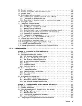
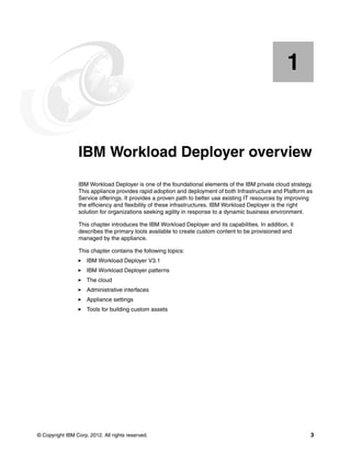
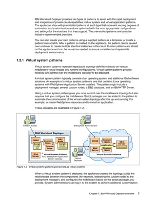
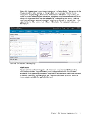
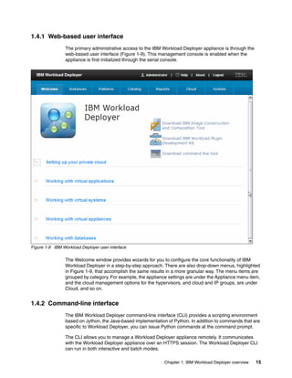
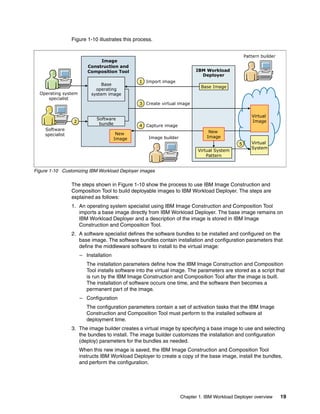
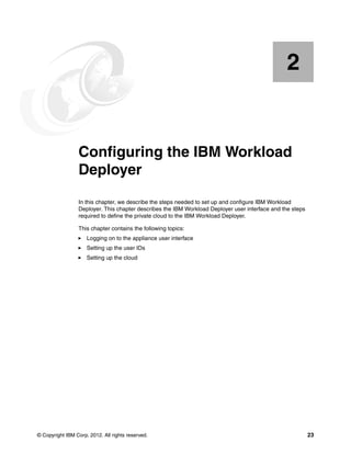
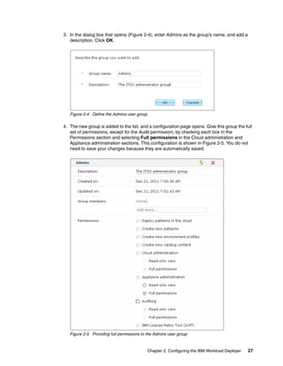
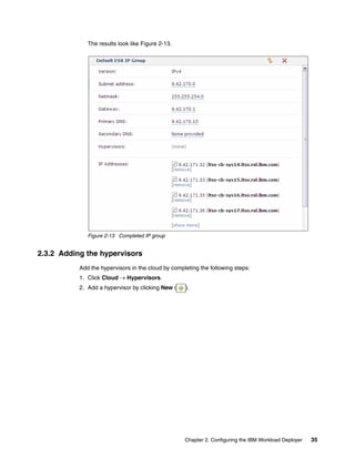
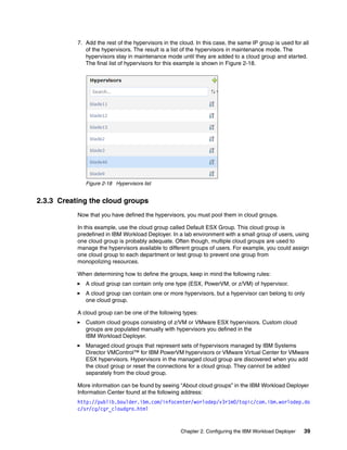
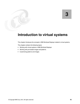
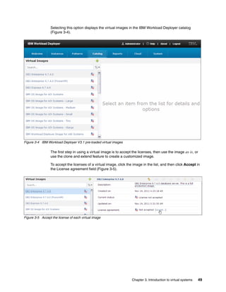
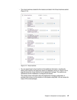
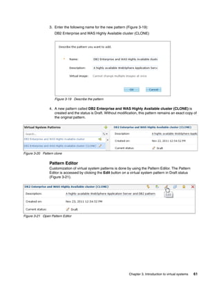
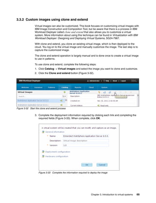
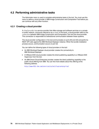
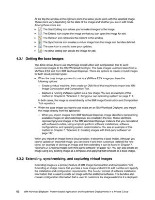
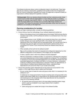
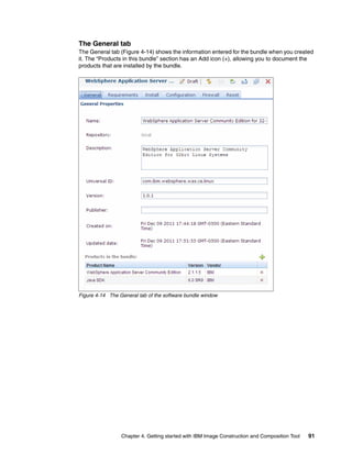
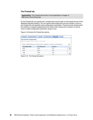
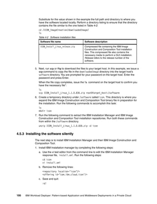
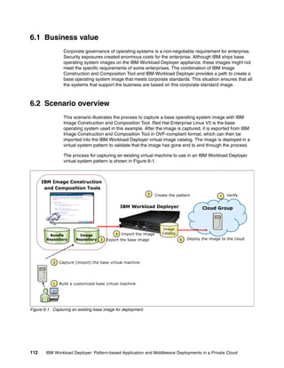
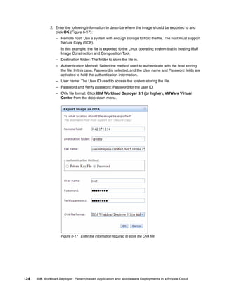
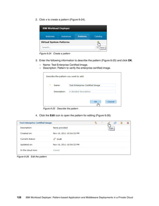
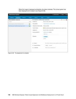
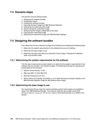
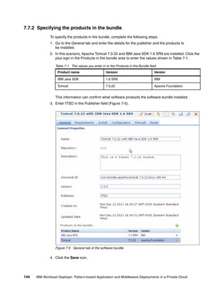
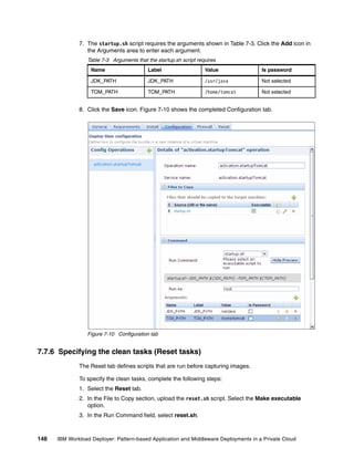
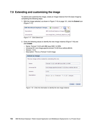
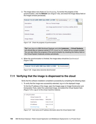
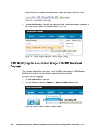
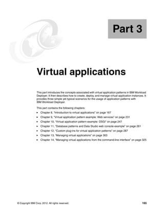
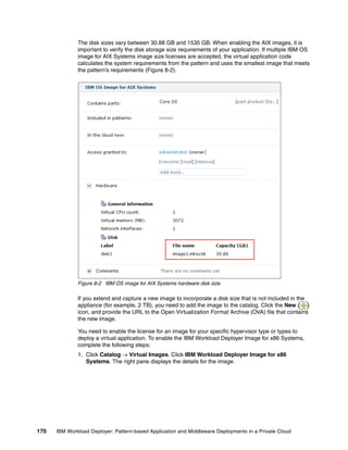
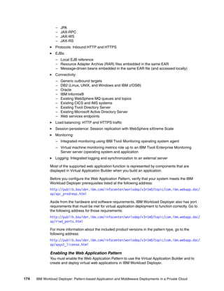
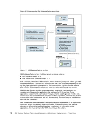
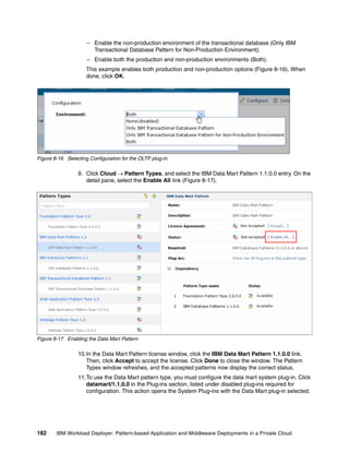
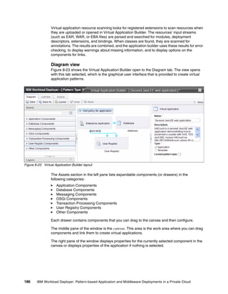
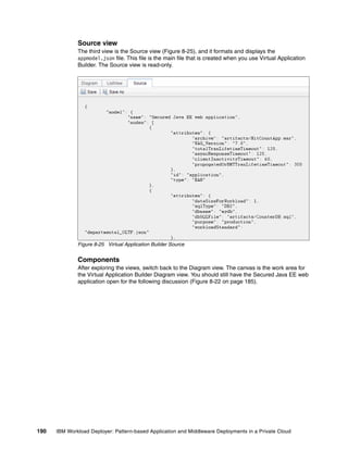
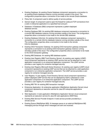
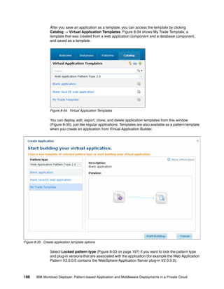
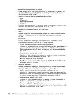
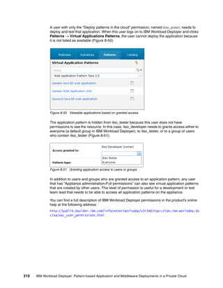
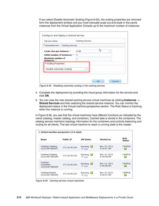
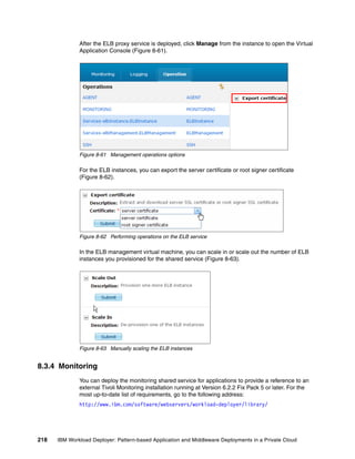
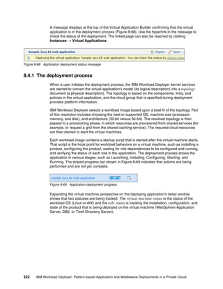
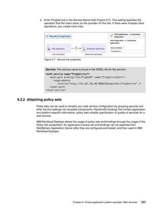
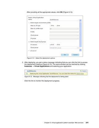
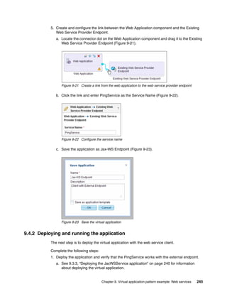
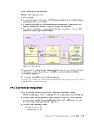
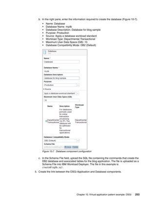
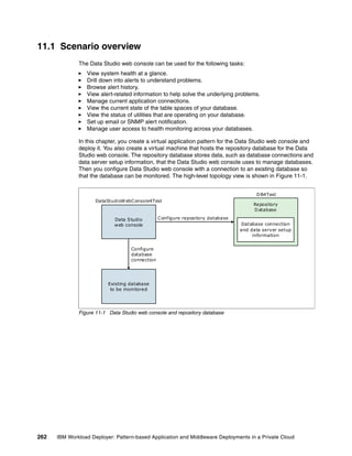
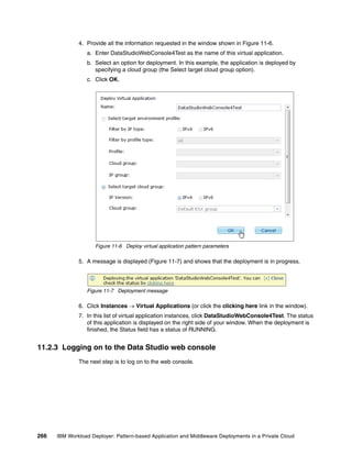
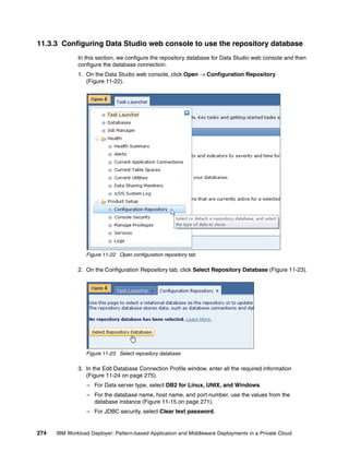
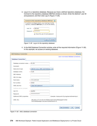
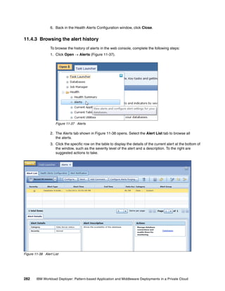
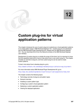
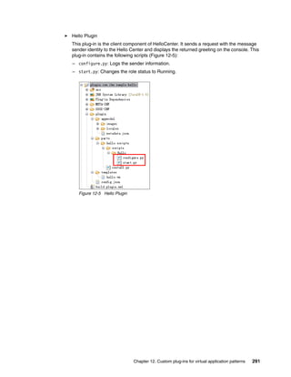
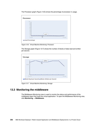
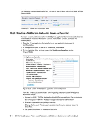
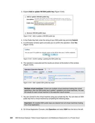
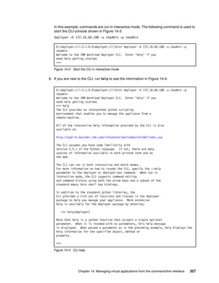
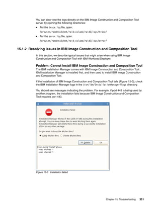
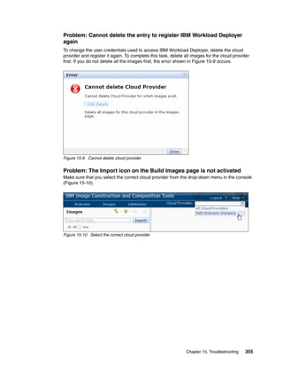
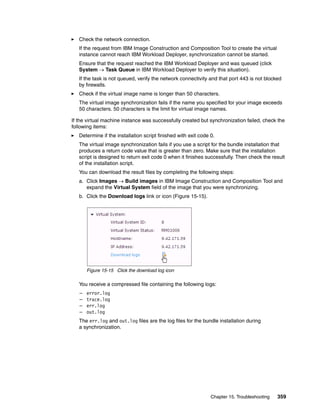
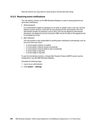
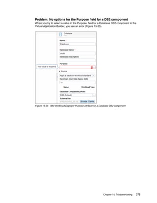
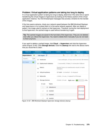
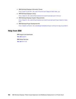
![Complete the following steps:
1. Open a terminal window to the host on which you deployed the software.
2. Change to the root directory into which the software was installed by running the
following command:
cd /opt/IBM/icon
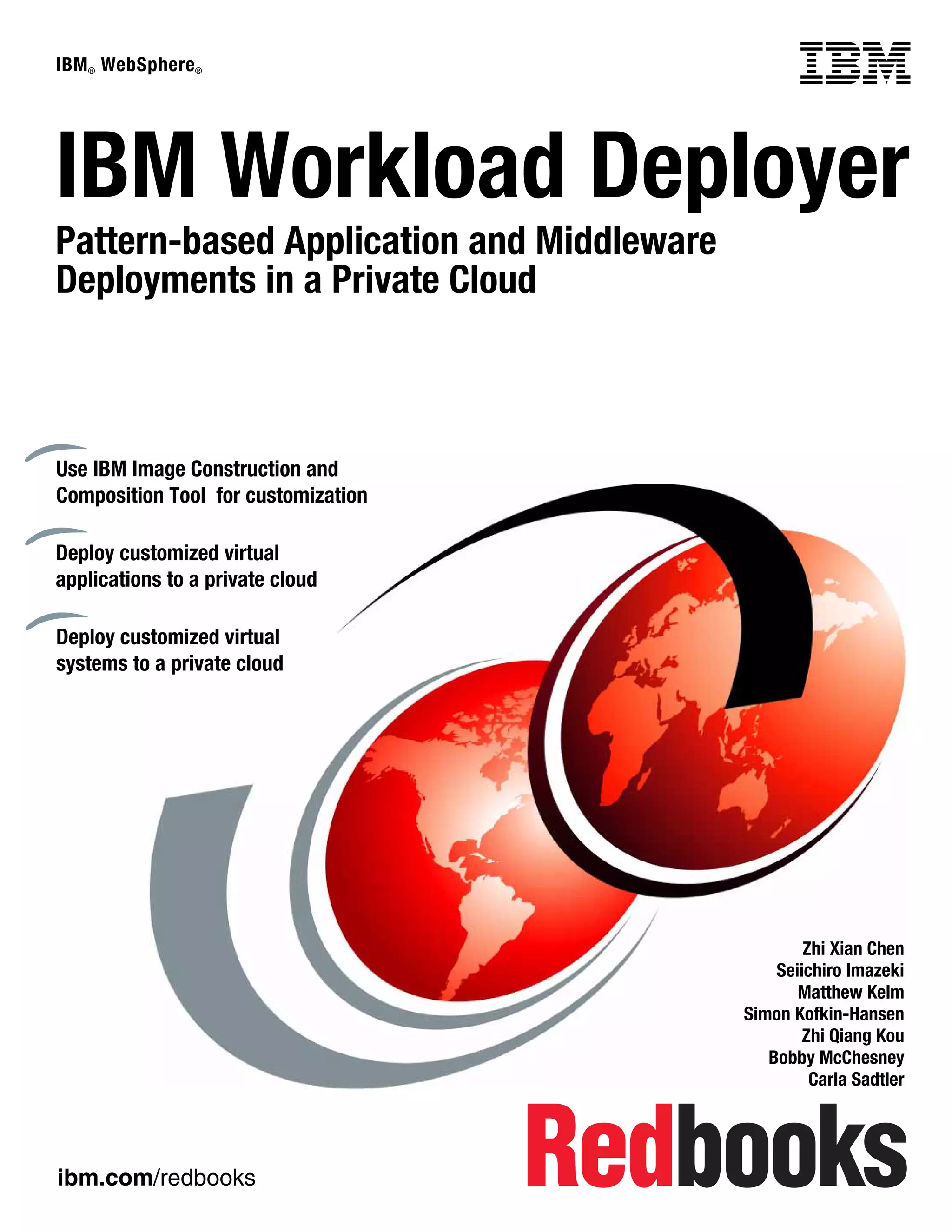
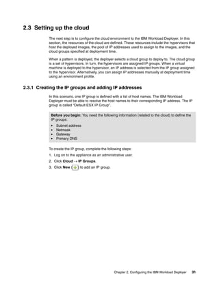
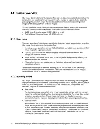
3. The start.sh and stop.sh scripts are used to start and stop the tool. Issue the start
command to validate that the tool can start and is operational:
./start.sh
Figure 4-23 shows the command issued to start the tool
[root@rcc-pok-idg-2210 /]# cd /opt/IBM/icon
[root@rcc-pok-idg-2210 icon]# ls
configICON.sh ibm-java-i386-60 icn.app installICON.sh license setupICON.sh start.sh stop.sh
[root@rcc-pok-idg-2210 icon]# ./start.sh
Application started and servicing requests at http://localhost:8080/ https://localhost:443/
CWPZT0600I: Command start was successful
Done start.sh
[root@rcc-pok-idg-2210 icon]# ./stop.sh
Application status is STOPPED
CWPZT0600I: Command stop was successful
Done stop.sh
[root@rcc-pok-idg-2210 icon]# ./start.sh
Application started and servicing requests at http://localhost:8080/ https://localhost:443/
Done start.sh
[root@rcc-pok-idg-2210 icon]#
Figure 4-23 Output of commands showing the successful start and shutdown of the tool
4.5.5 Logging in for the first time and creating a cloud provider
After the tool is running, you access it using a web browser. The optimum screen resolution
for viewing the tool browser interface is 1024 by 768. The supported browser types are:
Mozilla Firefox 3.6 and above (in our scenario, we used V7.0.1)
Microsoft Internet Explorer v7.x and v8.x
To log in and create a cloud provider, complete the following steps:
1. To access the tool interface, enter the following URL in your browser using the IP address
of the host on which you installed the tool:
https://host/icn/ui
Chapter 4. Getting started with IBM Image Construction and Composition Tool 103](https://image.slidesharecdn.com/sg248011-121226042448-phpapp02/85/IBM-Workload-Deployer-121-320.jpg)
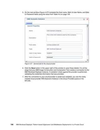


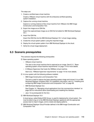
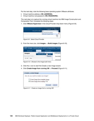
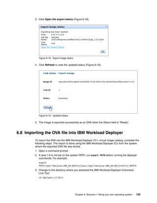
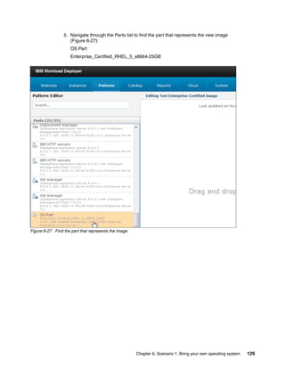
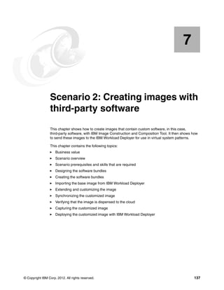
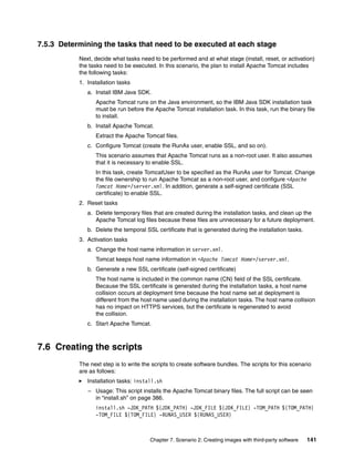
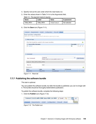
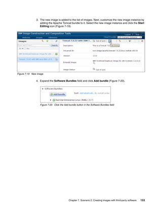
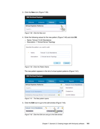


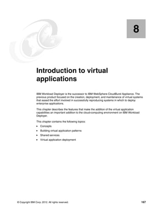
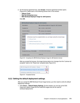
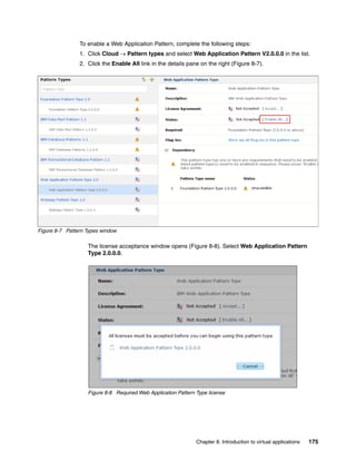
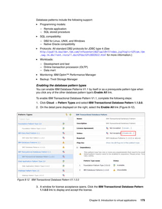
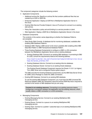
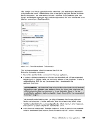
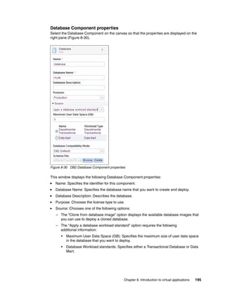
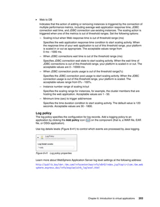
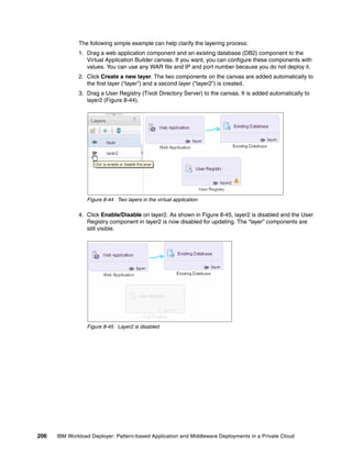
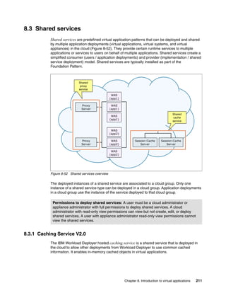
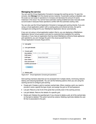
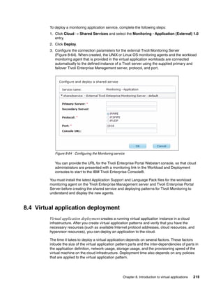


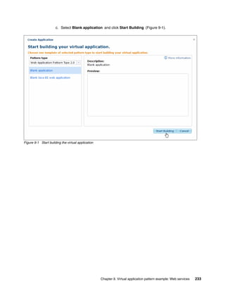
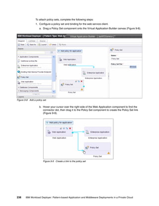
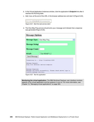
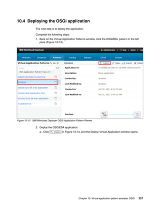

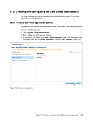
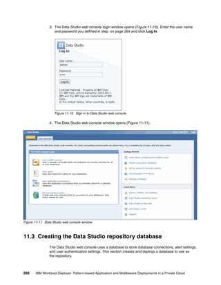
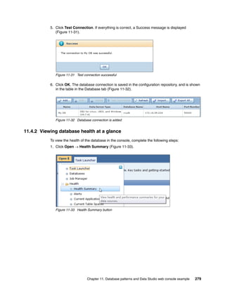
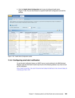

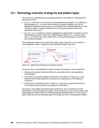
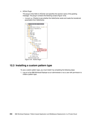
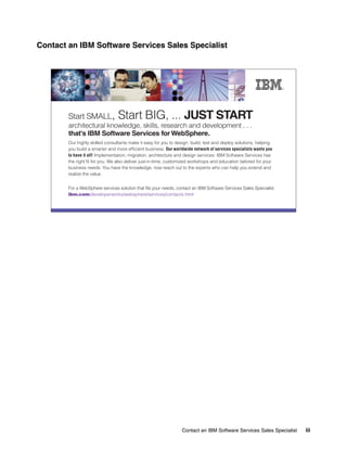
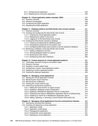
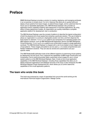
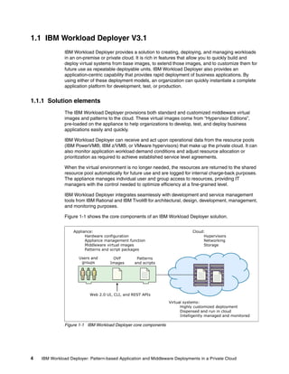
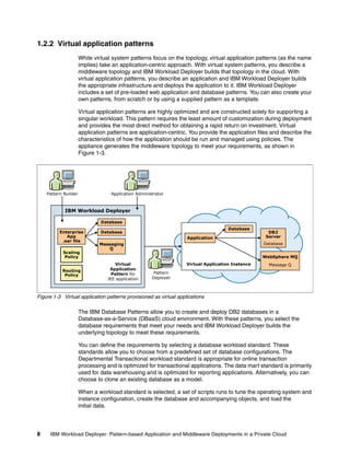
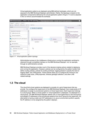
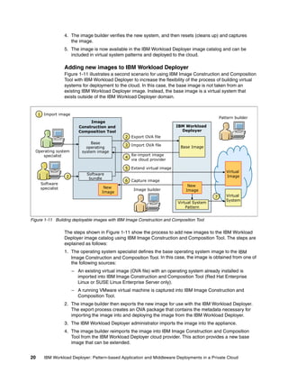
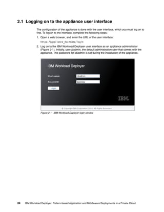
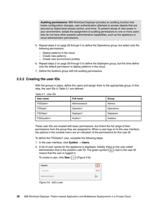
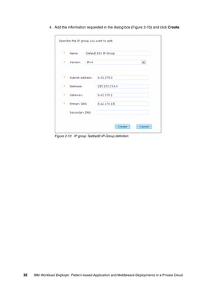
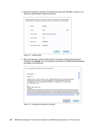
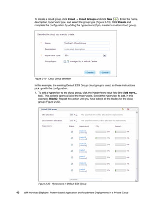
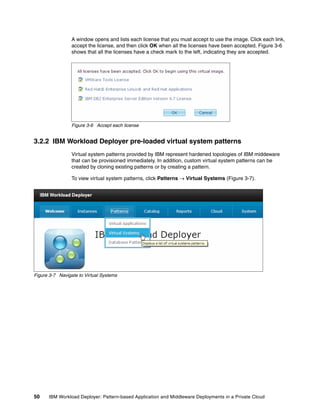
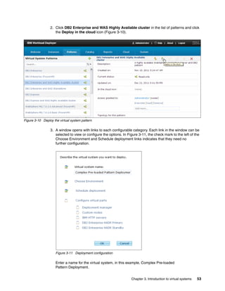
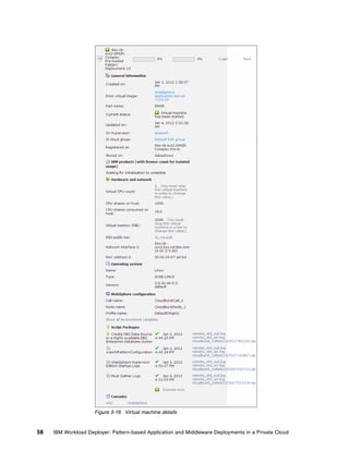
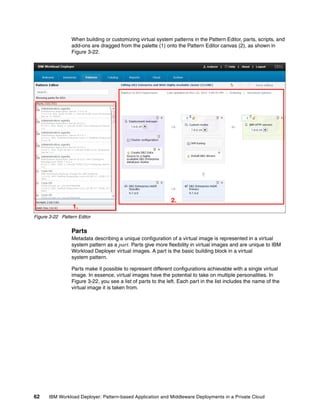
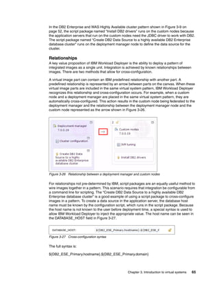
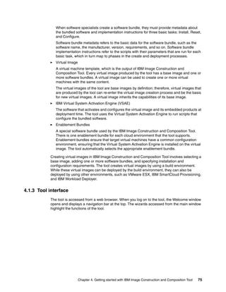
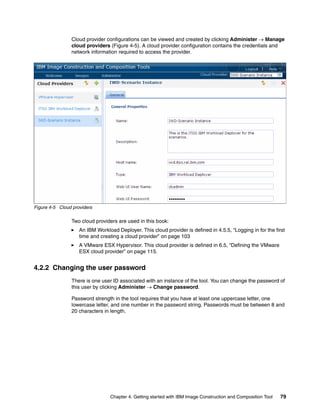
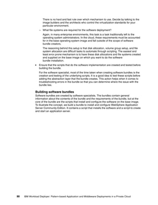
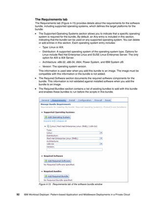
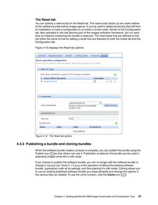
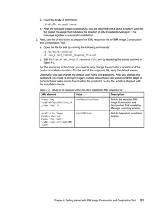
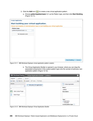
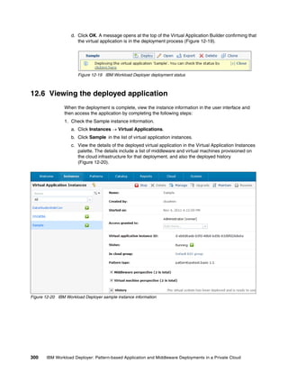
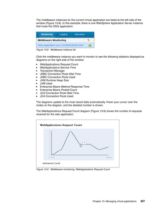
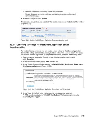
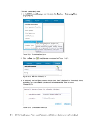
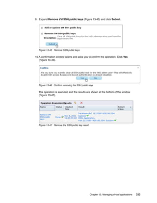
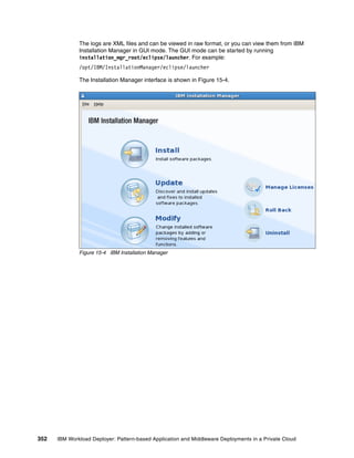
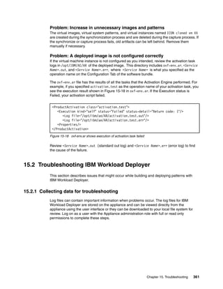
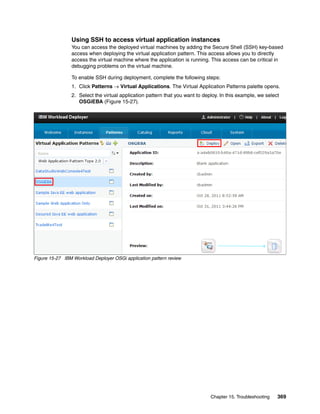
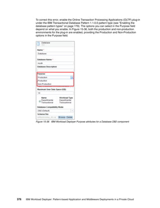
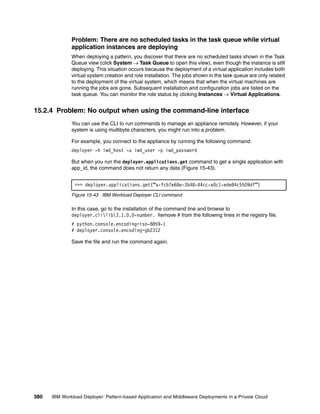
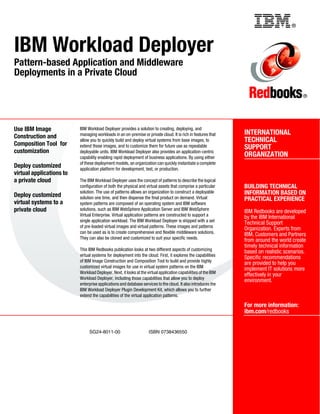
![7. Click Enable to change the pattern type status to Available (Figure 12-10).
Figure 12-10 IBM Workload Deployer custom pattern type status: Available
12.4 Configuring a custom virtual application pattern
You can now use the custom pattern type patterntypetest.basic 1.1 and the associated
plug-ins to design your own virtual application pattern.
Complete the following steps:
1. Create a file on your local file system named sample_userlist.json. This file contains the
sample input for the plug-in. The contents of the file is one line:
["Mike","Alice","Joe"]
2. In the IBM Workload Deployer user interface, click Patterns Virtual Applications to
open the Virtual Application Builder.
Chapter 12. Custom plug-ins for virtual application patterns 295](https://image.slidesharecdn.com/sg248011-121226042448-phpapp02/85/IBM-Workload-Deployer-313-320.jpg)
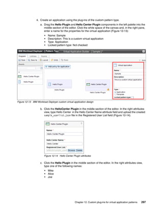
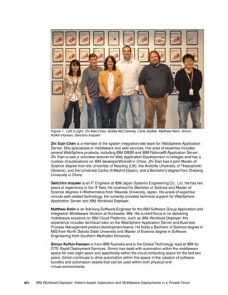
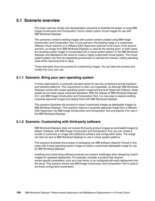
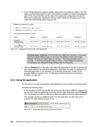
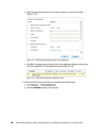
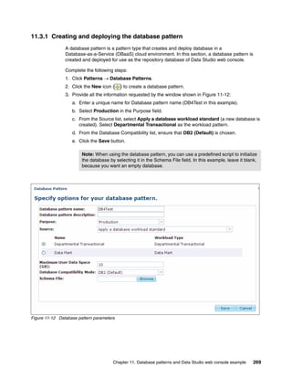
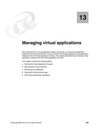
![2. Check the results of the Sample instance.
a. In the right side of palette in Figure 12-20 on page 300, find the row containing
Hello_Plugin-HVM-number in the virtual machine list (Figure 12-21).
Figure 12-21 Virtual machine of the Sample instance
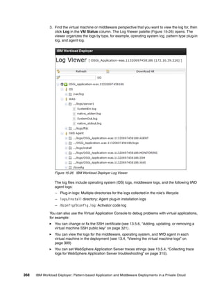
b. Click the Log link to the right of the “Running” status and a new tab opens
(Figure 12-22).
Figure 12-22 IBM Workload Deployer Log Viewer
c. In this log page, from the root, browse to the following entry (Figure 12-22).
IWD Agent > .../logs/Hello_Plugin-HVM.number.hello” > console.log
d. Click console.log to open the log. You should see the following messages indicating
that the communication between Hello Plugin and Hello Center Plugin was successful.
[2011-11-04 20:22:23,003] Hello/HCenter/changed.py 47035610148032 pid=17743
INFO Send the request to get a greeting message from Joe to Sherry
[2011-11-04 20:22:23,053] Hello/HCenter/changed.py 47035610148032 pid=17743
INFO Receive the meesage from hello center: Joe, a kind greeting message
from Sherry has been sent out.
Chapter 12. Custom plug-ins for virtual application patterns 301](https://image.slidesharecdn.com/sg248011-121226042448-phpapp02/85/IBM-Workload-Deployer-319-320.jpg)

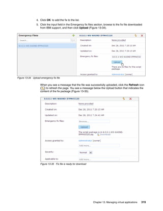

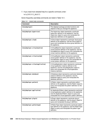
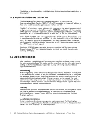
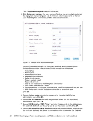
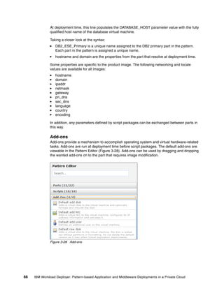
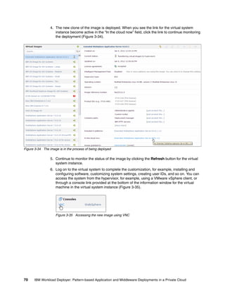
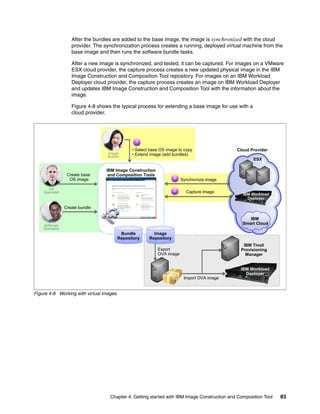
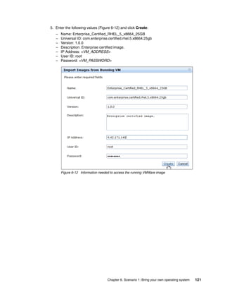
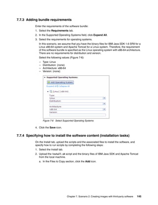
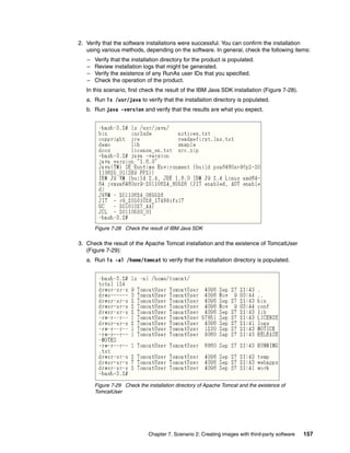
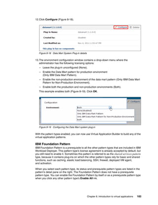
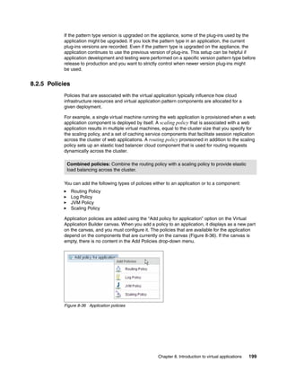
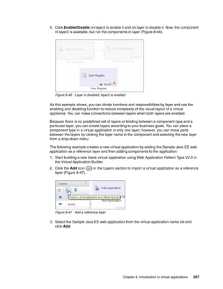
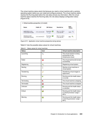
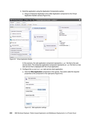
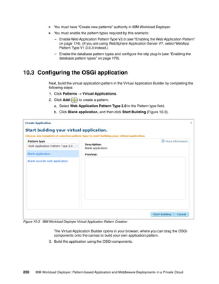
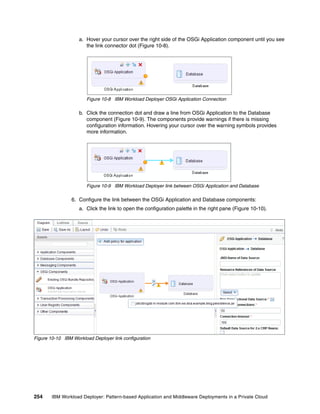
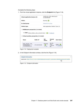
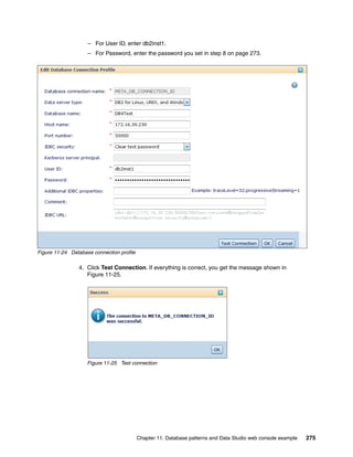
![14.2 Creating and deploying a virtual application
In this section, we create one Java EE web application from CLI. This application contains
two components, an enterprise application component that hosts a Java EE web application,
and a database component. The artifacts used for this example are:
EAR file: tradelite.ear
Database setup script: setup_db.sql
The attributes of the virtual application are described in two JSON files:
appmodel.json
appmodel_layout.json
14.2.1 Application model
The appmodel.json file describes the model and layer definition of the virtual application
(Example 14-1).
Example 14-1 appmodel.json
{
"layers":[{
"nodes":["application","database"],
"id":"layer_1",
"name":"layer_1"
}],
"model":{
"name":"SampleAppByCLI",
"description": "Sample Java EE web application created from CLI.",
"patterntype": "webapp",
"version":"2.0",
"app_type":"application",
"nodes":[
{
"id": "application",
"type": "EAR",
"attributes":{
"WAS_Version": "7.0",
"archive":"artifacts/tradelite.ear"
}
},
{
"id":"database",
"type":"DB2",
"attributes":{
"dataSizeForWorkload":1,
"sqlType":"DB2",
"dbname":"mydb",
"dbSQLFile":"artifacts/setup_db.sql",
"purpose":"production"
},
"groups":{
"cloneApproach":false,
"workloadStandardApproach":true
}
Chapter 14. Managing virtual applications from the command-line interface 329](https://image.slidesharecdn.com/sg248011-121226042448-phpapp02/85/IBM-Workload-Deployer-347-320.jpg)
![}],
"links":[{
"id":"application.database",
"type":"WASDB2",
"source":"application",
"target":"database",
"annotation":"",
"attributes":{
"connectionTimeout":180,
"nontransactional":false,
"maxConnectionPool":10,
"resourceRefs":[
"tradelite.war#jdbc/TradeDataSource"
]
}
}]
}
}
In the layers section, you can see there is only one layer in this application. Both the
application and database nodes are on this layer. (Layers are described in 8.2.6,
“Reference layering” on page 205.)
The model section defines:
– The name of the application (SampleAppByCLI).
– The patterntype of the application (webapp).
– The version of pattern type (2.0).
A node is defined with an ID of application:
– The type of artifact is EAR.
– The archive of the artifact is artifacts/tradelite.ear.
The artifacts folder is created and the artifacts are stored in it when you package the
virtual application
A node is defined with an ID of database:
– The type of the artifact is DB2.
– The dbname field indicates that the name of the database is mydb.
– The dbSQLFile field indicates that the script used to set up the database is
artifacts/setup_db.sql.
– The sqlType field indicates that the type of the script is DB2.
The links section defines the link between the two components:
– The type of the link is WASDB2.
– The source of the link is the application node.
– The target of the link is the database node.
– The resourceRefs attribute indicates that this link is a resource reference with the
name tradelite.war#jdbc/TradeDataSource.
330 IBM Workload Deployer: Pattern-based Application and Middleware Deployments in a Private Cloud](https://image.slidesharecdn.com/sg248011-121226042448-phpapp02/85/IBM-Workload-Deployer-348-320.jpg)
![14.2.2 Application model layout
The appmodel_layout.json file describes the layout information when the components of the
application are displayed in the Virtual Application Builder window (Example 14-2).
The ID of the nodes in the model layout file must match the ID of nodes in appmodel.json.
Example 14-2 appmodel_layout.json
{
"tooling":{
"nodes":[
{
"id":"application",
"location":{
"x": "10px",
"y": "150px"
}
},
{
"id":"database",
"location":{
"x":"300px",
"y":"150px"
}
}
],
"links":[]
}
}
14.2.3 Packaging the application
Place the two JSON files and all the artifacts in the folder structure shown in Example 14-3.
Example 14-3 Folder structure of the application
SampleAppByCLI
appmodel.json
appmodel_layout.json
artifacts
tradelite.ear
setup_db.sql
Then compress the whole SampleAppByCLI folder into an archive and save it as
D:SampleAppByCLI.zip.
14.2.4 Creating the virtual application
Enter the following command in the CLI to create the virtual application:
deployer.applications.create("D:SampleAppByCLI.zip")
Chapter 14. Managing virtual applications from the command-line interface 331](https://image.slidesharecdn.com/sg248011-121226042448-phpapp02/85/IBM-Workload-Deployer-349-320.jpg)
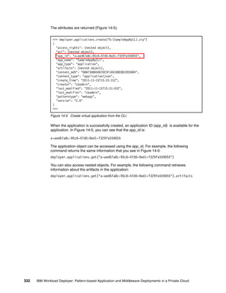
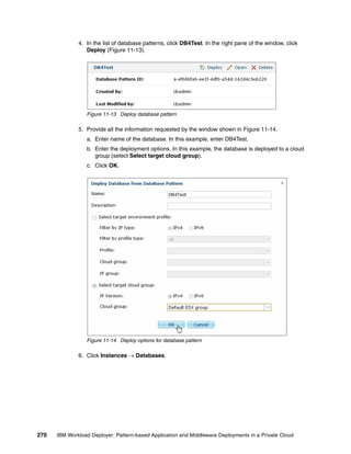
![As you can see in Figure 14-6, the tradelite.ear and setup_db.sql artifacts were created
correctly.
>>> deployer.applications.get("a-aed67a8c-95c6-47d0-9ed1-f329fa559055").artifacts
[
{
"access_rights": (nested object),
"application": (nested object),
"content_md5": "68C84965B52D8BC66D5DCB7CD0E2B774",
"content_type": "application/octet-stream",
"create_time": "2011-11-15T15:31:38Z",
"creator": "cbadmin",
"last_modified": "2011-11-15T15:31:38Z",
"last_modifier": "cbadmin",
"name": "setup_db.sql",
"sharedservice": (nested object)
},
{
"access_rights": (nested object),
"application": (nested object),
"content_md5": "9B67F070493B3DC30C314E355CD879B6",
"content_type": "application/octet-stream",
"create_time": "2011-11-15T15:31:40Z",
"creator": "cbadmin",
"last_modified": "2011-11-15T15:31:40Z",
"last_modifier": "cbadmin",
"name": "tradelite.ear",
"sharedservice": (nested object)
}
]
>>>
Figure 14-6 Get artifacts of a virtual application
14.2.5 Deploying a virtual application
The following command deploys the virtual application:
deployer.applications.get("a-aed67a8c-95c6-47d0-9ed1-f329fa559055").deploy("Sample
AppByCLI Deployment", deployer.clouds[0],"D:sshPubKey.txt")
In this example, the virtual application is deployed with the following parameters:
Name of the virtual application instance: SampleAppByCLI Deployment
Deploy to the first cloud group configured in this device: deployer.clouds[0]
The prepared SSH public key for the virtual machines: D:sshPubKey.txt
Chapter 14. Managing virtual applications from the command-line interface 333](https://image.slidesharecdn.com/sg248011-121226042448-phpapp02/85/IBM-Workload-Deployer-351-320.jpg)
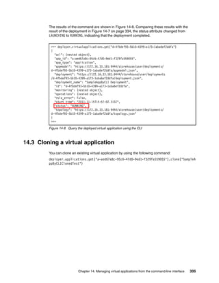
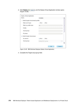
![The attributes of the virtual application instance are returned (Figure 14-7).
>>> deployer.applications.get("a-aed67a8c-95c6-47d0-9ed1-f329fa559055").deploy(
"SampleAppByCLI Deployment",deployer.clouds[0],"D:sshPubKey. txt")
{
"acl": (nested object),
"app_id": "a-aed67a8c-95c6-47d0-9ed1-f329fa559055",
"app_type": "application",
"appmodel": "https://172.16.33.181:9444/storehouse/user/deployments/
d-4fbdef93-5b10-4399-a173-1aba6ef2ddfa/appmodel.json",
"deployment": "https://172.16.33.181:9444/storehouse/user/deployments
/d-4fbdef93-5b10-4399-a173-1aba6ef2ddfa/deployment.json",
"deployment_name": "SampleAppByCLI Deployment",
"id": "d-4fbdef93-5b10-4399-a173-1aba6ef2ddfa",
"operations": (nested object),
"role_error": False,
"start_time": "2011-11-15T15:57:02.313Z",
"status": "LAUNCHING",
"topology": "https://172.16.33.181:9444/storehouse/user/deployments/
d-4fbdef93-5b10-4399-a173-1aba6ef2ddfa/topology.json"
}
>>>
Figure 14-7 Deploy a virtual application using the CLI
When the application is deployed, the instance is given an ID that can be used to access the
deployed virtual application object. In this example, the ID is:
d-4fbdef93-5b10-4399-a173-1aba6ef2ddfa
For example, the following command returns the attributes of the deployed virtual application:
deployer.virtualapplications.get("d-4fbdef93-5b10-4399-a173-1aba6ef2ddfa")
334 IBM Workload Deployer: Pattern-based Application and Middleware Deployments in a Private Cloud](https://image.slidesharecdn.com/sg248011-121226042448-phpapp02/85/IBM-Workload-Deployer-352-320.jpg)
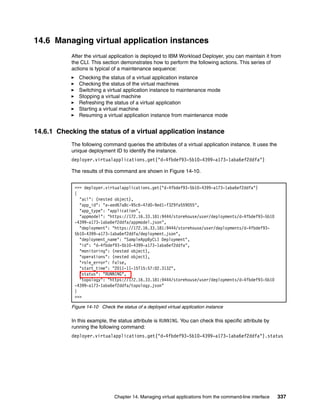
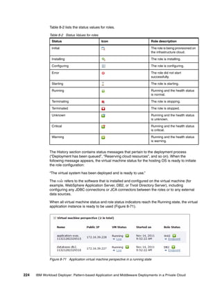
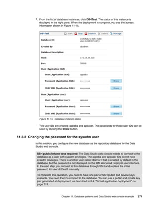
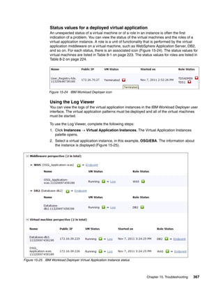
![14.6.2 Checking the status of the virtual machines
You can check the status of the virtual machines that host this virtual application instance by
running the following command:
deployer.virtualapplications.get("d-4fbdef93-5b10-4399-a173-1aba6ef2ddfa")
.vminstances().instances
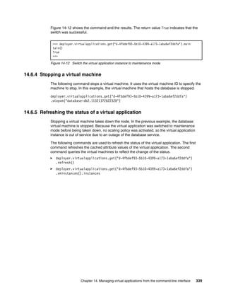
In the results shown in Figure 14-11, the status of both virtual machines is RUNNING. For a
detailed explanation of virtual machine status, see Table 8-1 on page 223
>>> deployer.virtualapplications.get("d-4fbdef93-5b10-4399-a173-1aba6ef2ddfa").vmin
stances().instances
[{
"id": "application-was.11321372622318",
"last_update": "2011-11-15T16:02:10.131Z",
"logging": (nested object),
"master": True,
"name": "application-was.11321372622318",
"private_ip": "172.16.39.230",
"public_ip": "172.16.39.230",
"reboot_count": 0,
"roles": (nested object),
"start_time": "2011-11-15T15:57:26.368Z",
"status": "RUNNING",
"vmId": 12,
"volumes": (nested object)
}, {
"id": "database-db2.11321372622328",
"last_update": "2011-11-15T16:02:10.131Z",
"logging": (nested object),
"name": "database-db2.11321372622328",
"private_ip": "172.16.39.229",
"public_ip": "172.16.39.229",
"reboot_count": 0,
"roles": (nested object),
"start_time": "2011-11-15T15:57:26.685Z",
"status": "RUNNING",
"vmId": 13,
"volumes": (nested object)
}]
>>>
Figure 14-11 Check the virtual machine status using the CLI
14.6.3 Switching a virtual application instance to maintenance mode
When a virtual application instance is in maintenance mode, you can stop and start the virtual
machines without activating the scaling policies. Run the following command to switch a
virtual application instance into maintenance mode.
deployer.virtualapplications.get("d-4fbdef93-5b10-4399-a173-1aba6ef2ddfa")
.maintain()
338 IBM Workload Deployer: Pattern-based Application and Middleware Deployments in a Private Cloud](https://image.slidesharecdn.com/sg248011-121226042448-phpapp02/85/IBM-Workload-Deployer-356-320.jpg)
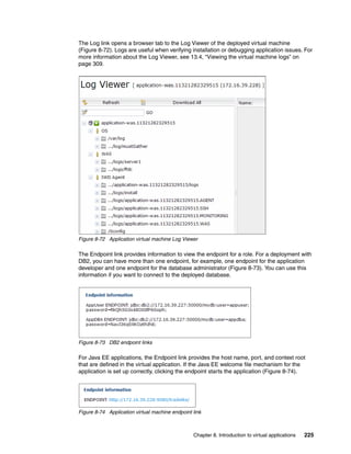
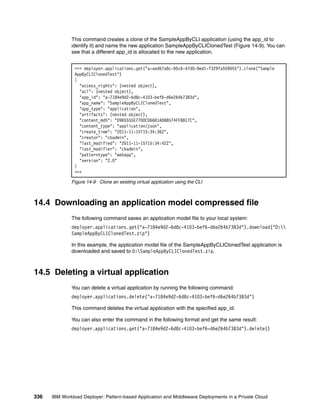
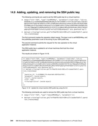
![The results of these commands, shown in Figure 14-13, show that the status of the virtual
application instance has changed to ERROR and the status of the database virtual machine is
changed to STOPPED.
>>> deployer.virtualapplications.get("d-4fbdef93-5b10-4399-a173-1aba6ef2ddfa").refre
sh()
{
"acl": (nested object),
"app_id": "a-aed67a8c-95c6-47d0-9ed1-f329fa559055",
"app_type": "application",
"appmodel": "https://172.16.33.181:9444/storehouse/user/deployments/d-4fbdef93-5b10
-4399-a173-1aba6ef2ddfa/appmodel.json",
"deployment": "https://172.16.33.181:9444/storehouse/user/deployments/d-4fbdef93
-5b10-4399-a173-1aba6ef2ddfa/deployment.json",
"deployment_name": "SampleAppByCLI Deployment",
"id": "d-4fbdef93-5b10-4399-a173-1aba6ef2ddfa",
"operations": (nested object),
"role_error": False,
"start_time": "2011-11-15T15:57:02.313Z",
"status": "ERROR",
"topology": "https://172.16.33.181:9444/storehouse/user/deployments/d-4fbdef93-5b10
-4399-a173-1aba6ef2ddfa/topology.json"
}
>>> deployer.virtualapplications.get("d-4fbdef93-5b10-4399-a173-1aba6ef2ddfa").vminst
ances().instances
[{
"id": "application-was.11321372622318",
"last_update": "2011-11-15T16:02:10.131Z",
"logging": (nested object),
"master": True,
"name": "application-was.11321372622318",
"private_ip": "172.16.39.230",
"public_ip": "172.16.39.230",
"reboot_count": 0,
"roles": (nested object),
"start_time": "2011-11-15T15:57:26.368Z",
"status": "RUNNING",
"vmId": 12,
"volumes": (nested object)
}, {
"id": "database-db2.11321372622328",
"last_update": "2011-11-15T22:20:58.272Z",
"logging": (nested object),
"name": "database-db2.11321372622328",
"private_ip": "172.16.39.229",
"public_ip": "172.16.39.229",
"reboot_count": 0,
"start_time": "2011-11-15T15:57:26.685Z",
"status": "STOPPED",
"vmId": 13,
"volumes": (nested object)
}]
>>>
Figure 14-13 Refresh status of the virtual application using the CLI
340 IBM Workload Deployer: Pattern-based Application and Middleware Deployments in a Private Cloud](https://image.slidesharecdn.com/sg248011-121226042448-phpapp02/85/IBM-Workload-Deployer-358-320.jpg)
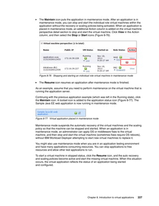
![14.6.6 Starting a virtual machine
The following command is used to start a virtual machine. In this example, the virtual machine
hosting the database is started.
deployer.virtualapplications.get("d-4fbdef93-5b10-4399-a173-1aba6ef2ddfa")
.startvm("database-db2.11321372622328")
Query the status of the virtual machine until you see it change to Running (see 14.6.2,
“Checking the status of the virtual machines” on page 338).
14.6.7 Resuming a virtual application instance from maintenance mode
The following command resumes the virtual application instance from maintenance mode:
deployer.virtualapplications.get("d-4fbdef93-5b10-4399-a173-1aba6ef2ddfa")
.resume()
Figure 14-14 shows the command and the results (True).
>>> deployer.virtualapplications.get("d-4fbdef93-5b10-4399-a173-1aba6ef2ddfa").resum e()
True
>>>>>>
Figure 14-14 Resume a virtual application instance from maintenance mode
14.7 Monitoring a virtual application
The following command can be used to monitor the metrics data of a virtual machine:
deployer.virtualapplications.get("d-4fbdef93-5b10-4399-a173-1aba6ef2ddfa").monitor
ing.servers[0].getMetrics()
The command returns the current metrics for the virtual machine (Figure 14-15).
>>> deployer.virtualapplications.get("d-4fbdef93-5b10-4399-a173-1aba6ef2ddfa").monito
ring.servers[0].getMetrics()
{'NETWORK': {'time_stamp': 1321462157665L, 'megabytes_received_per_sec': 0.001,
'megabytes_transmitted_per_sec': 0.001}, 'DISK': {'time_stamp': 1321462157665L,
'blocks_reads_per_second': 0L, 'blocks_written_per_second': 6077L}, 'MEMORY':
{'time_stamp': 1321462158651L, 'memory_used_percent': 9.0, 'memory_total': 2399L},
'CPU': {'time_stamp': 1321462158651L, 'busy_cpu': 2.32}}
>>>
Figure 14-15 Monitor virtual machine metrics data
If there are multiple virtual machines for the virtual application, you can monitor each of them
with the same command but specifying a different server index (servers[0]).
The following command can be used to monitor the metrics data for the middleware. The
command uses the roles parameter to specify the middleware to retrieve data from.
deployer.virtualapplications.get("d-4fbdef93-5b10-4399-a173-1aba6ef2ddfa").monitor
ing.roles[1].getMetrics()
Chapter 14. Managing virtual applications from the command-line interface 341](https://image.slidesharecdn.com/sg248011-121226042448-phpapp02/85/IBM-Workload-Deployer-359-320.jpg)
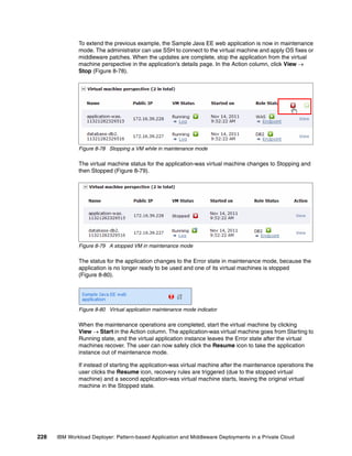
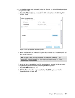
![This command returns WebSphere Application Server metrics data (Figure 14-16).
>>> deployer.virtualapplications.get("d-4fbdef93-5b10-4399-a173-1aba6ef2ddfa").monito
ring.roles[1].getMetrics()
{'WAS_JVMRuntime': {'time_stamp': 1321462093667L, 'jvm_heap_used': 74.952965,
'used_memory': 114744L, 'heap_size': 153088L}, 'WAS_TransactionManager': {'time_stamp':
1321462093667L, 'committed_count': 12L, 'rolledback_count': 0L, 'active_count': 0L},
'WAS_JDBCConnectionPools': {'min_wait_time': 0L, 'time_stamp': 1321462093667L,
'wait_time': 0L, 'max_percent_used': 0L, 'min_percent_used': 0L, 'percent_used': 0L,
'max_wait_time': 0L}, 'WAS_WebApplications': {'min_service_time': 0L, 'service_time':
0L, 'time_stamp': 1321462093667L, 'request_count': 0L, 'max
_service_time': 0L}}
>>>
Figure 14-16 Monitor WebSphere Application Server metrics data
In this example, roles[1] specifies WebSphere Application Server. The following command
is run to find which role object is WebSphere Application Server:
deployer.virtualapplications.get("d-4fbdef93-5b10-4399-a173-1aba6ef2ddfa")
.monitoring.roles
14.8 Downloading middleware log files
The following command lists the logs available for download from a virtual machine:
deployer.virtualapplications.get("d-4fbdef93-5b10-4399-a173-1aba6ef2ddfa")
.vminstances().instances[0].logging.getLogs()
342 IBM Workload Deployer: Pattern-based Application and Middleware Deployments in a Private Cloud](https://image.slidesharecdn.com/sg248011-121226042448-phpapp02/85/IBM-Workload-Deployer-360-320.jpg)
![In this example, the virtual machine hosts WebSphere Application Server, so the logs for
WebSphere Application Server are listed in the return message (Figure 14-17).
>>> deployer.virtualapplications.get("d-4fbdef93-5b10-4399-a173-1aba6ef2ddfa").vminstances()
.instances[0].logging.getLogs()
{'IWD Agent': ['/opt/IBM/maestro/agent/usr/servers/application-was.11321372622318/logs/trace.log.4',
'/opt/IBM/maestro/agent/usr/servers/application-was.11321372622318/logs/trace.log.5',
'/opt/IBM/maestro/agent/usr/servers/application-was.11321372622318/logs/ffdc.log.0',
'/opt/IBM/maestro/agent/usr/servers/application-was.11321372622318/logs/trace.log.2',
'/opt/IBM/maestro/agent/usr/servers/application-was.11321372622318/logs/trace.log.1',
'/opt/IBM/maestro/agent/usr/servers/application-was.11321372622318/logs/install/trace.log',
'/opt/IBM/maestro/agent/usr/servers/application-was.11321372622318/logs/install/console.log',
'/opt/IBM/maestro/agent/usr/servers/application-was.11321372622318/logs/trace.log.0',
'/opt/IBM/maestro/agent/usr/servers/application-was.11321372622318/logs/application-
was.11321372622318.MONITORING/trace.log',
'/opt/IBM/maestro/agent/usr/servers/application-was.11321372622318/logs/application-was.11321372622318.M
ONITORING/console.log',
'/opt/IBM/maestro/agent/usr/servers/application-was.11321372622318/logs/console.log.0',
'/opt/IBM/maestro/agent/usr/servers/application-was.11321372622318/logs/trace.log.8',
'/opt/IBM/maestro/agent/usr/servers/application-was.11321372622318/logs/trace.log.7',
'/opt/IBM/maestro/agent/usr/servers/application-was.11321372622318/logs/application-was.11321372622318.S
SH/trace.log',
'/opt/IBM/maestro/agent/usr/servers/application-was.11321372622318/logs/application-was.11321372622318.S
SH/console.log', '/opt/IBM/maestro/agent/usr/servers/application-was.11321372622318/logs/trace.log.6',
'/opt/IBM/maestro/agent/usr/servers/application-was.11321372622318/logs/application-was.11321372622318.W
AS/trace.log', '/opt/IBM/maestro/agent/usr/servers/application-was.11321372622318/logs/application-w
as.11321372622318.WAS/console.log',
'/opt/IBM/maestro/agent/usr/servers/application-was.11321372622318/logs/trace.log.3',
'/opt/IBM/maestro/agent/usr/servers/application-was.11321372622318/logs/application-was.11321372622318.A
GENT/trace.log',
'/opt/IBM/maestro/agent/usr/servers/application-was.11321372622318/logs/application-was.11321372622318.A
GENT/console.log', '/0config/0config.log'], 'WAS':
['/opt/IBM/WebSphere/AppServer/profiles/AppSrv01/logs/server1/native_stderr.log','/opt/IBM/WebSphere/App
Server/profiles/AppSrv01/logs/server1/SystemOut.log',
'/opt/IBM/WebSphere/AppServer/profiles/AppSrv01/logs/server1/SystemErr.log',
'/opt/IBM/WebSphere/AppServer/profiles/AppSrv01/logs/server1/native_stdout.log',
'/opt/IBM/WebSphere/AppServer/profiles/AppSrv01/logs/ffdc/server1_exception.log',
'/opt/IBM/WebSphere/AppServer/profiles/AppSrv01/logs/ffdc/server1_1e8db31f_11.11.15_16.14.59.29340938927
35162140204.txt',
'/opt/IBM/WebSphere/AppServer/profiles/AppSrv01/logs/ffdc/ffdc.9151162873764429136.txt',
'/opt/IBM/WebSphere/AppServer/profiles/AppSrv01/logs/ffdc/FfdcSummary.txt',
'/opt/IBM/WebSphere/AppServer/profiles/AppSrv01/logs/ffdc/ffdc.6089871315269192617.txt'], 'OS':
['/var/log/dmesg', '/var/log/maillog', '/var/log/secure','/var/log/boot.log', '/var/log/brcm-iscsi.log',
'/var/log/spooler', '/var/log/messages', '/var/log/yum.log', '/var/log/cron',
'/var/log/acpid','/var/log/wtmp']}
>>>
Figure 14-17 List all available logs for downloading
The following commands are used to download a log file to your local system:
vm=deployer.virtualapplications.get("d-4fbdef93-5b10-4399-a173-1aba6ef2ddfa")
.vminstances().instances[0]
vm.logging.download("/opt/IBM/WebSphere/AppServer/profiles/AppSrv01/logs/
server1/SystemOut.log","D:SystemOut.log")
The first command returns the virtual machine object. The second command downloads the
log file for the virtual machine object to the local system by specifying the source and target
path names of the log file.
Chapter 14. Managing virtual applications from the command-line interface 343](https://image.slidesharecdn.com/sg248011-121226042448-phpapp02/85/IBM-Workload-Deployer-361-320.jpg)


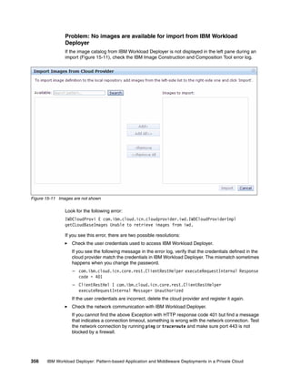
![Check the out.log file for the output of the installation script. If you find a message with an
error, for example, ERROR: step execution failed: ICONXX” (Figure 15-16), your
installation task failed. Review the err.log file to find the cause of the error.
[2011-11-16 17:10:29,629] INFO: Created system services for activation.
EXIT step: activation.ConfigIcon
EXIT task: group
ENTER task: IconTask
ENTER step: ICON96963lo1m5tr48s83kbbi6ecrb1
This script always returns the exit code 1
ERROR: step execution failed: ICON96963lo1m5tr48s83kbbi6ecrb1
Figure 15-16 The out.log file shows the failure of the installation tasks
After resolving the issue, try to extend and synchronize the image again.
Check if a timeout error occurred.
IBM Workload Deployer can take a long time to create a virtual instance. The time varies
depending on network speed, size of the image, and other factors. An indication of a
timeout can be seen in the Image status field in IBM Image Construction and Composition
Tool.
Figure 15-17 Image Status is unable to connect to the virtual machine
IBM Image Construction and Composition Tool waits 3 hours for the virtual machine
instance to start and waits 6 hours for the Installation Tasks to finish running. If either
process exceeds the timeout, the synchronization is considered a failure.
You might experience this situation when you synchronize a large image for the first time
because IBM Workload Deployer must transfer the virtual image files to the
hypervisor cache.
If you experience this situation, try to extend and synchronize again. If the same issue
occurs, consider improving the network performance, scale up the capacity of the
hypervisor resource, change the cloud environment, and so on.
Problem: Failure to capture an image
If a capture from IBM Image Construction and Composition Tool for an image in IBM
Workload Deployer fails, check the IBM Image Construction and Composition Tool error.log
file for the following items:
If you see an HTTP response code 401 (unauthorized) error, verify the credentials of the
user accessing the cloud provider.
Log on to IBM Workload Deployer and ensure that the virtual instance is running. Check
the network connection.
If the request from IBM Image Construction and Composition Tool to create the virtual
instance cannot reach IBM Workload Deployer, the image capture cannot be started.
Ensure that there are not any problems with the network connection.
360 IBM Workload Deployer: Pattern-based Application and Middleware Deployments in a Private Cloud](https://image.slidesharecdn.com/sg248011-121226042448-phpapp02/85/IBM-Workload-Deployer-378-320.jpg)
![3. Expand Mail Delivery.
4. Enter the values for the following attributes (Figure 15-23):
SMTP server: IP address or host name
Reply-to address: An email address
Figure 15-23 IBM Workload Deployer Mail Delivery setup
You can receive the following notifications:
Deployment started
Deploying a virtual application pattern generates the email shown in Example 15-1.
Example 15-1 Deployment started notification
Subject:
[Workload Deployer] Deployment started: d-1c7ce179-ea5f-485d-afb7-0b15896e1dc2
Body:
Workload Deployer has started deploying your virtual system. You will be
notified again when the system is ready for use.
To login to the appliance, please visit
https://esx-v4-033-181.purescale.raleigh.ibm.com.
IP address in use
The appliance runs ping to verify the available IP addresses in an IP group when you start
a deployment and look for the next available IP address. If a response is received, an
email stating that a device is running on that IP even though it is marked as inactive in IBM
Workload Deployer is generated.
Chapter 15. Troubleshooting 365](https://image.slidesharecdn.com/sg248011-121226042448-phpapp02/85/IBM-Workload-Deployer-383-320.jpg)
![The content of the email is shown in Example 15-2.
Example 15-2 IP address in use notification
Subject:
[Workload Deployer] IP addresses in use, but marked inactive
Body:
The following IP addresses are marked as inactive but can be pinged in the
network: 9.42.39.227 9.42.39.228
To login to the appliance, please visit https://esx-v4.itso.raleigh.ibm.com.
Deployment succeeded
If the deployment succeeds, an email is generated (Example 15-3).
Example 15-3 Deployment succeeded notification
Subject:
[Workload Deployer] Deployment succeeded: d-1c7ce179-ea5f-485d-afb7-0b15896e1dc2
Body:
Workload Deployer has completed deployment of your virtual system. All virtual machines
have been started and are ready for use.
To login to the appliance, please visit https://esx-v4.itso.raleigh.ibm.com.
Deployment failed
If the deployment fails, an email with the cause of the failure is generated (Example 15-4).
Example 15-4 Deployment failed notification
Subject:
[Workload Deployer] Deployment failed: d-94db7aea-e059-46f5-9dc8-c857f397dbb6
Body:
Workload Deployer could not complete deployment of your virtual system due
to the following error: Virtual machine could not be registered.
15.2.3 Troubleshooting virtual applications
Virtual applications are application-centric. The infrastructure and virtual systems that the
application run on are not immediately apparent to the IBM Workload Deployer administrator.
This situation can present some challenges when things go wrong. This section provides
troubleshooting tips for working with virtual applications in IBM Workload Deployer.
366 IBM Workload Deployer: Pattern-based Application and Middleware Deployments in a Private Cloud](https://image.slidesharecdn.com/sg248011-121226042448-phpapp02/85/IBM-Workload-Deployer-384-320.jpg)
![Accessing virtual machines with SSH
After deploying the virtual application pattern, you can use the IP address of the virtual
machines and the private key to gain access to the application artifacts. To do so, complete
the following steps:
1. To gain access to your virtual machine after deployment, run the following command:
ssh -i id_rsa.txt virtuser@<your_workload_ip>
Or you can use SCP to gain access, for example, by running:
scp -i id_rsa.txt myfiles.txt
virtuser@<your_workload_ip>:/[location]/myfile.txt
2. Log on to the virtual machine.
To gain root access, run the following command:
sudo su -
Run a command with root access, for example:
sudo /sbin/ifconfig
You can view and monitor statistics for your deployed virtual machines now.
Accessing virtual machines with the hypervisor
If something goes wrong when deploying a database pattern and the Manage button is
disabled for the instance (Figure 15-32), you cannot enable SSH to access the virtual
machine to check log files. You can use the VMware vSphere Client to log on to ESX
hypervisors, allowing you to access the machine.
Determine the IP address for the virtual machine by opening the window for the database
instance (Figure 15-32).
Figure 15-32 IBM Workload Deployer database instance information
Log on to the ESX hypervisor with the VMware vSphere Client and locate the virtual machine
with the same IP address. From there, you can locate log and configuration information for
the middleware, applications, and so on, and view them to determine the problem.
Chapter 15. Troubleshooting 373](https://image.slidesharecdn.com/sg248011-121226042448-phpapp02/85/IBM-Workload-Deployer-391-320.jpg)
![WebSphere Application Server Community Edition scripts
These scripts are used in the examples found in Chapter 4, “Getting started with IBM Image
Construction and Composition Tool” on page 73.
installWASCE.sh
Example A-1 contains the script used in a software bundle to install WebSphere Application
Server Community Edition.
Example A-1 installWASCE.sh
#!/bin/sh
#
# Copyright IBM Corp. 2011
# All Rights Reserved
# This information contains sample code provided in source code form. You may
copy, modify, and distribute these sample programs in any form without payment to
IBM for the purposes of developing, using, marketing or distributing application
programs conforming to the application programming interface for the operating
platform for which the sample code is written. Notwithstanding anything to the
contrary, IBM PROVIDES THE SAMPLE SOURCE CODE ON AN "AS IS" BASIS AND IBM
DISCLAIMS ALL WARRANTIES, EXPRESS OR IMPLIED, INCLUDING, BUT NOT LIMITED TO, ANY
IMPLIED WARRANTIES OR CONDITIONS OF MERCHANTABILITY, SATISFACTORY QUALITY, FITNESS
FOR A PARTICULAR PURPOSE, TITLE, AND ANY WARRANTY OR CONDITION OF
NON-INFRINGEMENT. IBM SHALL NOT BE LIABLE FOR ANY DIRECT, INDIRECT, INCIDENTAL,
SPECIAL OR CONSEQUENTIAL DAMAGES ARISING OUT OF THE USE OR OPERATION OF THE SAMPLE
SOURCE CODE. IBM HAS NO OBLIGATION TO PROVIDE MAINTENANCE, SUPPORT, UPDATES,
ENHANCEMENTS OR MODIFICATIONS TO THE SAMPLE SOURCE CODE.
mkdir /mytest
mkdir /tmp/wasce
env > /tmp/wasce/install.env
NOT_SET="<NOT_SET>"
WASCE_TAR_URL=$NOT_SET
WASCE_TAR_NAME=wasce_ibm60sdk_setup-2.1.1.5-ia32linux.tar.bz2
JAVA_RPM_NAME=ibm-java-i386-sdk-6.0-9.0.i386.rpm
INSTALLED_JAVA_HOME=/opt/ibm/java-i386-60
WASCE_TAR_URL_USER=$NOT_SET
WASCE_TAR_URL_PASSWORD=$NOT_SET
WASCE_INSTALL_EXEC=wasce_setup-2.1.1.5-unix.bin
while [ $# -ne 0 ]
do
case $1 in
-WASCE_INSTALL_PATH*)
WASCE_INSTALL_PATH=$2
;;
-TAR_URL*)
WASCE_TAR_URL=$2
;;
-TAR_NAME*)
WASCE_TAR_NAME=$2
382 IBM Workload Deployer: Pattern-based Application and Middleware Deployments in a Private Cloud](https://image.slidesharecdn.com/sg248011-121226042448-phpapp02/85/IBM-Workload-Deployer-400-320.jpg)
![;;
-INSTALL_EXEC*)
WASCE_INSTALL_EXEC=$2
;;
-URL_USERID*)
WASCE_TAR_URL_USER=$2
;;
-URL_PASSWORD*)
WASCE_TAR_URL_PASSWORD=$2
;;
-JAVA_RPM_NAME*)
JAVA_RPM_NAME=$2
;;
-JAVA_INSTALLED_HOME*)
INSTALLED_JAVA_HOME=$2
;;
*)
;;
esac
shift 1; shift 1
done
echo "WASCE_INSTALL_PATH is set to: $WASCE_INSTALL_PATH"
echo "TAR_URL is set to: $WASCE_TAR_URL"
echo "TAR_NAME is set to: $WASCE_TAR_NAME"
echo "INSTALL_EXEC is set to: $WASCE_INSTALL_EXEC"
echo "URL_USERID is set to: $WASCE_TAR_URL_USER"
echo "URL_PASSWORD is set to: $WASCE_TAR_URL_PASSWORD"
echo "JAVA_RPM_NAME is set to: $JAVA_RPM_NAME" >> $logfile
echo "JAVA_INSTALLED_HOME is set to: $INSTALLED_JAVA_HOME"
#Write the install path to a file so configuration script can share value
echo "$WASCE_INSTALL_PATH" >> /tmp/wasce/wasce_install_path
# Write the install path to a properties file we will use for silent install
echo "USER_INSTALL_DIR=$WASCE_INSTALL_PATH" >> /tmp/wasce/install.props
cd /tmp/wasce
# Retrieve the WebSphere Application Server Community Edition binaries and untar
if [ $WASCE_TAR_URL_PASSWORD = $NOT_SET ]
then
echo "wget $WASCE_TAR_URL"
wget $WASCE_TAR_URL
else
echo "wget --user $WASCE_TAR_URL_USER --password $WASCE_TAR_URL_PASSWORD
--no-check-certificate $WASCE_TAR_URL"
wget --user $WASCE_TAR_URL_USER --password $WASCE_TAR_URL_PASSWORD
--no-check-certificate $WASCE_TAR_URL
fi
if [ $? -eq 0 ]
Appendix A. Sample scripts 383](https://image.slidesharecdn.com/sg248011-121226042448-phpapp02/85/IBM-Workload-Deployer-401-320.jpg)
![then
echo "WGET binary '$WASCE_TAR_URL' successful"
else
echo "WGET binary '$WASCE_TAR_URL' failed!"
exit 100
fi
echo "tar -xvf $WASCE_TAR_NAME"
tar -xvf $WASCE_TAR_NAME
if [ $? -eq 0 ]
then
echo "Untar source '$WASCE_TAR_NAME' successful"
else
echo "Untar source '$WASCE_TAR_NAME' failed!"
exit 200
fi
# If the package contains a Java RPM, install it
if [ "X$JAVA_RPM_NAME" != "X" ] ; then
echo "rpm -ivh $JAVA_RPM_NAME"
rpm -ivh $JAVA_RPM_NAME
else
echo "Java already installed"
fi
# Make sure Java is in the path for installation
export PATH=$PATH:$INSTALLED_JAVA_HOME/bin
chmod 777 $WASCE_INSTALL_EXEC
# Initiate the silent installation fo WebSphere Application Server Community
Edition
cat ./install.props
echo "./$WASCE_INSTALL_EXEC -i silent -f ./install.props"
./$WASCE_INSTALL_EXEC -i silent -f ./install.props
cd ../
# Remove the temporary directory
#rm -rf /tmp/wasce
exit 0
ConfigWASCE.sh
Example A-2 contains the script used in a software bundle to configure and start a
WebSphere Application Server Community Edition server.
Example A-2 ConfigWASCE.sh
#!/bin/bash
# Copyright IBM Corp. 2011
384 IBM Workload Deployer: Pattern-based Application and Middleware Deployments in a Private Cloud](https://image.slidesharecdn.com/sg248011-121226042448-phpapp02/85/IBM-Workload-Deployer-402-320.jpg)
![# All Rights Reserved
# This information contains sample code provided in source code form. You may
copy, modify, and distribute these sample programs in any form without payment to
IBM for the purposes of developing, using, marketing or distributing application
programs conforming to the application programming interface for the operating
platform for which the sample code is written. Notwithstanding anything to the
contrary, IBM PROVIDES THE SAMPLE SOURCE CODE ON AN "AS IS" BASIS AND IBM
DISCLAIMS ALL WARRANTIES, EXPRESS OR IMPLIED, INCLUDING, BUT NOT LIMITED TO, ANY
IMPLIED WARRANTIES OR CONDITIONS OF MERCHANTABILITY, SATISFACTORY QUALITY, FITNESS
FOR A PARTICULAR PURPOSE, TITLE, AND ANY WARRANTY OR CONDITION OF
NON-INFRINGEMENT. IBM SHALL NOT BE LIABLE FOR ANY DIRECT, INDIRECT, INCIDENTAL,
SPECIAL OR CONSEQUENTIAL DAMAGES ARISING OUT OF THE USE OR OPERATION OF THE SAMPLE
SOURCE CODE. IBM HAS NO OBLIGATION TO PROVIDE MAINTENANCE, SUPPORT, UPDATES,
ENHANCEMENTS OR MODIFICATIONS TO THE SAMPLE SOURCE CODE.
HOSTNAME=`hostname -f`
echo "Configuring WAS CE with host $HOSTNAME"
if [ ! -n $HOSTNAME ]
then
HOSTNAME=`cat /etc/HOSTNAME`
fi
#WASCE_HOME=/opt/IBM/WebSphere/AppServerCommunityEdition
num_servers=1
WASCE_ADMIN_USER="wasceadmin"
WASCE_ADMIN_PASSWORD="password"
while [ $# -ne 0 ]
do
case $1 in
-num_servers*)
num_servers=$2
;;
-WASCE_HOME*)
WASCE_HOME=$2
;;
-WASCE_ADMIN_USER*)
WASCE_ADMIN_USER=$2
;;
-WASCE_ADMIN_PASSWORD*)
WASCE_ADMIN_PASSWORD=$2
;;
*)
;;
esac
shift 1; shift 1
done
#Read WASCE install path from install script breadcrumb
if [ -f /tmp/wasce/wasce_install_path ]
then
WASCE_HOME=$(echo /tmp/wasce/install_path)
Appendix A. Sample scripts 385](https://image.slidesharecdn.com/sg248011-121226042448-phpapp02/85/IBM-Workload-Deployer-403-320.jpg)
![svr_ct=1
sed -i s/"EndPointURI=http.*"/"EndPointURI=http://$HOSTNAME:8080"/g
$WASCE_HOME/var/config/config-substitutions.properties
sed -i s/"ServerHostname=0.0.0.0"/"ServerHostname=$HOSTNAME"/g
$WASCE_HOME/var/config/config-substitutions.properties
sed -i s/"RemoteDeployHostname=localhost"/"RemoteDeployHostname=$HOSTNAME"/g
$WASCE_HOME/var/config/config-substitutions.properties
sed -i
s/"system=Simple}rO0ABXNyABlqYXZheC5jcnlwdG8uU2VhbGVkT2JqZWN0PjY9psO3VHACAARbAA1lb
mNvZGVkUGFyYW1zdAACW0JbABBlbmNyeXB0ZWRDb250ZW50cQB+AAFMAAlwYXJhbXNBbGd0ABJMamF2YS9
sYW5nL1N0cmluZztMAAdzZWFsQWxncQB+AAJ4cHB1cgACW0Ks8xf4BghU4AIAAHhwAAAAEHnh03EmiNu4V
TuWH+xZiRBwdAADQUVT"/""/g $WASCE_HOME/var/security/users.properties
echo "$WASCE_ADMIN_USER=$WASCE_ADMIN_PASSWORD" >>
$WASCE_HOME/var/security/users.properties
sed -i s/"admin=system"/"admin=$WASCE_ADMIN_USER"/g
$WASCE_HOME/var/security/groups.properties
$WASCE_HOME/bin/startup.sh
echo "Configuring $num_servers server instance(s)"
while [ $svr_ct -lt $num_servers ]
do
let svr_ct++
instName="instance"$svr_ct
echo "Creating $instName instance"
mkdir $WASCE_HOME/$instName
cp -r $WASCE_HOME/var $WASCE_HOME/$instName
let y=$svr_ct-1
sed -i s/"PortOffset=0"/"PortOffset=$y"/g
$WASCE_HOME/$instName/var/config/config-substitutions.properties
GERONIMO_OPTS=-Dorg.apache.geronimo.server.name=$instName
export GERONIMO_OPTS=$GERONIMO_OPTS
$WASCE_HOME/bin/geronimo.sh start
echo "Started $instName instance"
done
Scripts for Apache Tomcat installation
These scripts are used in Chapter 7, “Scenario 2: Creating images with third-party software”
on page 137.
install.sh
This script (Example A-3) installs the Apache Tomcat binary files.
Example A-3 install.sh
#!/bin/bash
#
# Copyright IBM Corp. 2011
386 IBM Workload Deployer: Pattern-based Application and Middleware Deployments in a Private Cloud](https://image.slidesharecdn.com/sg248011-121226042448-phpapp02/85/IBM-Workload-Deployer-404-320.jpg)
![# All Rights Reserved
# This information contains sample code provided in source code form. You may
copy, modify, and distribute these sample programs in any form without payment to
IBM for the purposes of developing, using, marketing or distributing application
programs conforming to the application programming interface for the operating
platform for which the sample code is written. Notwithstanding anything to the
contrary, IBM PROVIDES THE SAMPLE SOURCE CODE ON AN "AS IS" BASIS AND IBM
DISCLAIMS ALL WARRANTIES, EXPRESS OR IMPLIED, INCLUDING, BUT NOT LIMITED TO, ANY
IMPLIED WARRANTIES OR CONDITIONS OF MERCHANTABILITY, SATISFACTORY QUALITY, FITNESS
FOR A PARTICULAR PURPOSE, TITLE, AND ANY WARRANTY OR CONDITION OF
NON-INFRINGEMENT. IBM SHALL NOT BE LIABLE FOR ANY DIRECT, INDIRECT, INCIDENTAL,
SPECIAL OR CONSEQUENTIAL DAMAGES ARISING OUT OF THE USE OR OPERATION OF THE SAMPLE
SOURCE CODE. IBM HAS NO OBLIGATION TO PROVIDE MAINTENANCE, SUPPORT, UPDATES,
ENHANCEMENTS OR MODIFICATIONS TO THE SAMPLE SOURCE CODE.
#
# ----------------------------------------------------------------
HOSTNAME=`hostname -f`
echo "Installing Tomcat with host $HOSTNAME"
if [ ! $HOSTNAME ]
then
HOSTNAME=`cat /etc/HOSTNAME`
fi
WORK_DIR=`pwd`
while [ $# -ne 0 ]
do
case $1 in
-JDK_PATH*)
JDK_PATH=$2
echo "JDK_PATH=$JDK_PATH"
;;
-JDK_FILE*)
JDK_FILE=$2
echo "JDK_FILE=$JDK_FILE"
;;
-TOM_PATH*)
TOM_PATH=$2
echo $TOM_PATH
echo "TOM_PATH=$TOM_PATH"
;;
-TOM_FILE*)
TOM_FILE=$2
echo $TOM_FILE
echo "TOM_FILE=$TOM_FILE"
;;
-RUNAS_USER*)
RUNAS_USER=$2
echo "RUNAS_USER=$RUNAS_USER"
;;
*)
;;
esac
shift 1; shift 1
Appendix A. Sample scripts 387](https://image.slidesharecdn.com/sg248011-121226042448-phpapp02/85/IBM-Workload-Deployer-405-320.jpg)
![done
# Check parameters
if [ "X" == "X$JDK_PATH" ] ;then
JDK_PATH=/usr/java
echo "JDK_PATH=$JDK_PATH"
fi
if [ "X" == "X$JDK_FILE" ] ;then
JDK_FILE=ibm-java-sdk-6.0-9.2-linux-x86_64.bin
echo "JDK_FILE=$JDK_FILE"
fi
if [ "X" == "X$TOM_PATH" ] ;then
TOM_PATH=/home/tomcat
echo "TOM_PATH=$TOM_PATH"
fi
if [ "X" == "X$TOM_FILE" ] ;then
TOM_FILE=apache-tomcat-7.0.22.zip
echo "TOM_FILE=$TOM_FILE"
fi
if [ "X" == "X$RUNAS_USER" ] ;then
RUNAS_USER=TomcatUser
echo "RUNAS_USER=$RUNAS_USER"
fi
#-- Install JDK --#
if [ -e ${WORK_DIR}/${JDK_FILE} ] ;then
chmod +x ${WORK_DIR}/${JDK_FILE}
mkdir -p /opt/ibm
mv ${WORK_DIR}/${JDK_FILE} /opt/ibm/
cd /opt/ibm/
/opt/ibm/${JDK_FILE} -i silent
if [ $? = 0 ] ;then
rm -f /opt/ibm/${JDK_FILE}
JDK_TEMP=`ls -d /opt/ibm/ibm*`
ln -s ${JDK_TEMP} ${JDK_PATH}
echo "Install JDK: OK" >> /opt/result
else
echo "Install JDK: NG" >> /opt/result
exit 1
fi
fi
alternatives --display java |grep gcj
if [ $? != 0 ] ;then
echo "GCJ: The GNU Compiler for Java is not installed."
fi
alternatives --install /usr/bin/java java ${JDK_PATH}/bin/java 2000
--slave /usr/lib/jvm/jre jre ${JDK_PATH}/jre
388 IBM Workload Deployer: Pattern-based Application and Middleware Deployments in a Private Cloud](https://image.slidesharecdn.com/sg248011-121226042448-phpapp02/85/IBM-Workload-Deployer-406-320.jpg)
![--slave /usr/bin/javaws javaws ${JDK_PATH}/bin/javaws
--slave /usr/bin/keytool keytool ${JDK_PATH}/bin/keytool
--slave /usr/bin/rmiregistry rmiregistry ${JDK_PATH}/bin/rmiregistry
--slave /usr/lib/jvm-exports/jre jre_exports ${JDK_PATH}/bin/jre
if [ $? = 0 ] ;then
echo ""
echo "Setup JDK: OK" >> /opt/result
else
echo "Setup JDK: NG" >> /opt/result
exit 1
fi
# End of Install JDK
cd ${WORK_DIR}
#-- Install Tomcat --#
# Add RunAsUser
cut -d: -f1 /etc/passwd |grep ${RUNAS_USER}
if [ $? != 0 ] ;then
/usr/sbin/useradd ${RUNAS_USER}
fi
# Verify RunAsUser
if [ $? = 0 ] ;then
cut -d: -f1 /etc/passwd |grep ${RUNAS_USER}
if [ $? = 0 ] ;then
echo "Make RunAsUser: OK" >> /opt/result
else
echo "Make RunAsUser: NG" >> /opt/result
exit 1
fi
else
echo "Make RunAsUser: NG" >> /opt/result
exit 1
fi
# Install Tomcat #
if [ -e ${WORK_DIR}/${TOM_FILE} ];then
mv ${WORK_DIR}/${TOM_FILE} /home/${RUNAS_USER}/
cd /home/${RUNAS_USER}/
unzip /home/${RUNAS_USER}/${TOM_FILE}
if [ $? = 0 ] ;then
echo "Tomcat: UNZIP OK" >> /opt/result
else
echo "Tomcat: UNZIP NG" >> /opt/result
exit 1
fi
rm -f /home/${RUNAS_USER}/${TOM_FILE}
Appendix A. Sample scripts 389](https://image.slidesharecdn.com/sg248011-121226042448-phpapp02/85/IBM-Workload-Deployer-407-320.jpg)
![TOM_TEMP=`echo ${TOM_FILE} |cut -d. -f1-3`
ln -s /home/${RUNAS_USER}/${TOM_TEMP} ${TOM_PATH}
fi
# Enable SSL
cp -p ${TOM_PATH}/conf/server.xml ${TOM_PATH}/conf/server.xml.org
num1=`grep -n '<Connector port="8443"' ${TOM_PATH}/conf/server.xml |cut -d: -f1`
(( num1 = num1 -1 ))
sed -e ${num1}d ${TOM_PATH}/conf/server.xml > ${TOM_PATH}/conf/temp
num2=`grep -n 'sslProtocol="TLS" />' ${TOM_PATH}/conf/temp |cut -d: -f1`
(( num2 = num2 +1 ))
sed -e ${num2}d ${TOM_PATH}/conf/temp > ${TOM_PATH}/conf/server.xml
if [ $? = 0 ] ;then
echo "Tomcat: SSL setting is completed." >> /opt/result
else
echo "Tomcat: SSL setting is incompleted." >> /opt/result
exit 1
fi
# Generate SSL key
sudo -u ${RUNAS_USER} keytool -genkey -dname "CN=`hostname -f`, OU=IBM Redbooks,
O=IBM, L=Raleigh, S=North Carolina, C=US" -alias tomcat -keyalg RSA -keypass
changeit -storepass changeit
sudo -u ${RUNAS_USER} keytool -list -alias tomcat -storepass changeit
if [ $? = 0 ] ;then
echo "Getnerate SSL Certificate: OK" >> /opt/result
else
echo "Getnerate SSL Certificate: NG" >> /opt/result
exit 1
fi
# Change Owner
chown -R ${RUNAS_USER}:${RUNAS_USER} ${TOM_PATH}
chown -R ${RUNAS_USER}:${RUNAS_USER} /home/${RUNAS_USER}/${TOM_TEMP}
chmod 744 ${TOM_PATH}/bin/*.sh
# Edit .bash_profile of RunAs User
echo "export JRE_HOME=${JDK_PATH}" >> /home/${RUNAS_USER}/.bash_profile
echo "export CATALINA_HOME=${TOM_PATH}" >> /home/${RUNAS_USER}/.bash_profile
if [ $? = 0 ] ;then
echo "Install Tomcat: OK" >> /opt/result
else
echo "Install Tomcat: NG" >> /opt/result
exit 1
fi
# Restart firewall
#/etc/rc.d/init.d/iptables restart
#iptables -P OUTPUT ACCEPT
#iptables-save > /etc/sysconfig/iptables
390 IBM Workload Deployer: Pattern-based Application and Middleware Deployments in a Private Cloud](https://image.slidesharecdn.com/sg248011-121226042448-phpapp02/85/IBM-Workload-Deployer-408-320.jpg)
![startup.sh
This script (Example A-4) starts Apache Tomcat.
Example A-4 startup.sh
#!/bin/bash
#
# Copyright IBM Corp. 2011
# All Rights Reserved
# This information contains sample code provided in source code form. You may
copy, modify, and distribute these sample programs in any form without payment to
IBM for the purposes of developing, using, marketing or distributing application
programs conforming to the application programming interface for the operating
platform for which the sample code is written. Notwithstanding anything to the
contrary, IBM PROVIDES THE SAMPLE SOURCE CODE ON AN "AS IS" BASIS AND IBM
DISCLAIMS ALL WARRANTIES, EXPRESS OR IMPLIED, INCLUDING, BUT NOT LIMITED TO, ANY
IMPLIED WARRANTIES OR CONDITIONS OF MERCHANTABILITY, SATISFACTORY QUALITY, FITNESS
FOR A PARTICULAR PURPOSE, TITLE, AND ANY WARRANTY OR CONDITION OF
NON-INFRINGEMENT. IBM SHALL NOT BE LIABLE FOR ANY DIRECT, INDIRECT, INCIDENTAL,
SPECIAL OR CONSEQUENTIAL DAMAGES ARISING OUT OF THE USE OR OPERATION OF THE SAMPLE
SOURCE CODE. IBM HAS NO OBLIGATION TO PROVIDE MAINTENANCE, SUPPORT, UPDATES,
ENHANCEMENTS OR MODIFICATIONS TO THE SAMPLE SOURCE CODE.
#
# ----------------------------------------------------------------
while [ $# -ne 0 ]
do
case $1 in
-JDK_PATH*)
JDK_PATH=$2
echo "JDK_PATH=$JDK_PATH"
;;
-TOM_PATH*)
TOM_PATH=$2
echo $TOM_PATH
echo "TOM_PATH=$TOM_PATH"
;;
*)
;;
esac
shift 1; shift 1
done
# Check parameters
if [ "X" == "X$JDK_PATH" ] ;then
JDK_PATH=/usr/java
echo "JDK_PATH=$JDK_PATH"
fi
if [ "X" == "X$TOM_PATH" ] ;then
TOM_PATH=/home/tomcat
echo "TOM_PATH=$TOM_PATH"
fi
Appendix A. Sample scripts 391](https://image.slidesharecdn.com/sg248011-121226042448-phpapp02/85/IBM-Workload-Deployer-409-320.jpg)
![RUNAS_USER=`ls -al ${TOM_PATH} |cut -d " " -f3`
echo "RunAS User: ${RUNAS_USER}" >> /opt/result
# Change hostname
sudo -u ${RUNAS_USER} cp -p ${TOM_PATH}/conf/server.xml
${TOM_PATH}/conf/server.xml.org
sudo -u ${RUNAS_USER} sed -e s/localhost/`hostname -f`/g
${TOM_PATH}/conf/server.xml.org > ${TOM_PATH}/conf/server.xml
# Generate SSL key
sudo -u ${RUNAS_USER} keytool -list -alias tomcat -storepass changeit
if [ $? = 0 ] ;then
echo "Old SSL Certificate: Remain" >> /opt/result
sudo -u ${RUNAS_USER} keytool -delete -alias tomcat -storepass changeit
fi
sudo -u ${RUNAS_USER} keytool -genkey -dname "CN=`hostname -f`, OU=IBM Redbooks,
O=IBM, L=Raleigh, S=North Carolina, C=US" -alias tomcat -keyalg RSA -keypass
changeit -storepass changeit
sudo -u ${RUNAS_USER} keytool -list -alias tomcat -storepass changeit
if [ $? = 0 ] ;then
echo "Getnerate SSL Certificate: OK" >> /opt/result
else
echo "Getnerate SSL Certificate: NG" >> /opt/result
exit 1
fi
# Start Tomcat
JRE_HOME=${JDK_PATH}/jre
CATALINA_HOME=${TOM_PATH}
sudo -u ${RUNAS_USER} ${TOM_PATH}/bin/startup.sh
ps -ef |grep java |grep -v grep
if [ $? = 0 ] ;then
echo "START Tomcat: OK" >> /opt/result
else
echo "START Tomcat: NG" >> /opt/result
fi
# Restart firewall
#mv /opt/iptables /etc/sysconfig/iptables
#/etc/rc.d/init.d/iptables restart
reset.sh
This script (Example A-5) performs tasks that clean up the image before capture.
Example A-5 reset.sh
#!/bin/bash
#
392 IBM Workload Deployer: Pattern-based Application and Middleware Deployments in a Private Cloud](https://image.slidesharecdn.com/sg248011-121226042448-phpapp02/85/IBM-Workload-Deployer-410-320.jpg)
![# Copyright IBM Corp. 2011
# All Rights Reserved
# This information contains sample code provided in source code form. You may
copy, modify, and distribute these sample programs in any form without payment to
IBM for the purposes of developing, using, marketing or distributing application
programs conforming to the application programming interface for the operating
platform for which the sample code is written. Notwithstanding anything to the
contrary, IBM PROVIDES THE SAMPLE SOURCE CODE ON AN "AS IS" BASIS AND IBM
DISCLAIMS ALL WARRANTIES, EXPRESS OR IMPLIED, INCLUDING, BUT NOT LIMITED TO, ANY
IMPLIED WARRANTIES OR CONDITIONS OF MERCHANTABILITY, SATISFACTORY QUALITY, FITNESS
FOR A PARTICULAR PURPOSE, TITLE, AND ANY WARRANTY OR CONDITION OF
NON-INFRINGEMENT. IBM SHALL NOT BE LIABLE FOR ANY DIRECT, INDIRECT, INCIDENTAL,
SPECIAL OR CONSEQUENTIAL DAMAGES ARISING OUT OF THE USE OR OPERATION OF THE SAMPLE
SOURCE CODE. IBM HAS NO OBLIGATION TO PROVIDE MAINTENANCE, SUPPORT, UPDATES,
ENHANCEMENTS OR MODIFICATIONS TO THE SAMPLE SOURCE CODE.
#
# ----------------------------------------------------------------
HOSTNAME=`hostname -f`
echo "RESET"
if [ ! $HOSTNAME ]
then
HOSTNAME=`cat /etc/HOSTNAME`
fi
while [ $# -ne 0 ]
do
case $1 in
-TOM_PATH*)
TOM_PATH=$2
echo "TOM_PATH=$TOM_PATH"
;;
*)
;;
esac
shift 1; shift 1
done
# Check parameters
if [ "X" == "X$TOM_PATH" ] ;then
TOM_PATH=/home/tomcat
echo "TOM_PATH=$TOM_PATH"
fi
RUNAS_USER=`ls -al ${TOM_PATH} |cut -d " " -f3`
#echo "RunAS User: ${RUNAS_USER}" >> /opt/result
# Remove unnecessary files of Apache Tomcat
rm -f ${TOM_PATH}/conf/temp
rm -f ${TOM_PATH}/logs/*
# Remove the temporary SSL certificate
sudo -u ${RUNAS_USER} keytool -delete -alias tomcat -storepass changeit
if [ $? = 0 ] ;then
Appendix A. Sample scripts 393](https://image.slidesharecdn.com/sg248011-121226042448-phpapp02/85/IBM-Workload-Deployer-411-320.jpg)
![echo "Delete SSL Certificate: OK" >> /opt/result
else
echo "Delete SSL Certificate: NG" >> /opt/result
fi
#iptables-save > /opt/iptables
if [ $? = 0 ] ;then
echo "Copy Firewall Setting: OK" >> /opt/result
else
echo "Copy Firewall Setting: NG" >> /opt/result
fi
Plugin Development Kit Hello Center example
This section contains the contents of the scripts in the Hello Center example described in
Chapter 12, “Custom plug-ins for virtual application patterns” on page 287.
HCenter plug-in scripts
The HCenter plug-in contains the scripts shown in Example A-6 through Example A-9 on
page 396.
Example A-6 Install.py
#
#*===================================================================
#*
#* Licensed Materials - Property of IBM
#* IBM Workload Deployer (7199-72X)
#* Copyright IBM Corporation 2009, 2011. All Rights Reserved.
#* US Government Users Restricted Rights - Use, duplication or disclosure
#* restricted by GSA ADP Schedule Contract with IBM Corp.
#*
#*===================================================================
#
import maestro
# Prepare (chmod +x, dos2unix) and copy scripts to the agent scriptdir
maestro.install_scripts('scripts')
Example A-7 Configure.py
#
#*===================================================================
#*
#* Licensed Materials - Property of IBM
#* IBM Workload Deployer (7199-72X)
#* Copyright IBM Corporation 2009, 2011. All Rights Reserved.
#* US Government Users Restricted Rights - Use, duplication or disclosure
#* restricted by GSA ADP Schedule Contract with IBM Corp.
#*
#*===================================================================
394 IBM Workload Deployer: Pattern-based Application and Middleware Deployments in a Private Cloud](https://image.slidesharecdn.com/sg248011-121226042448-phpapp02/85/IBM-Workload-Deployer-412-320.jpg)
![#
import maestro
import json
import os
import sys
import logging;
import subprocess
PORT = 4000;
#import the hcenter utils module.
hcscriptspath = os.path.join(maestro.node['scriptdir'],'HCenter');
if not hcscriptspath in sys.path:
sys.path.append(hcscriptspath)
from hcenterutils import sendCmd
logger = logging.getLogger("HCenter/configure.py")
installdir = maestro.node['parts']['HCenter']['installDir']
#start the server and open the port in firewall for Hello Center;
subprocess.Popen([os.path.join(installdir,"start.sh")]);
maestro.firewall.open_tcpin(src='private', dport=str(PORT));
tmpdir = maestro.role['tmpdir']
userfile = maestro.parms['User_File']
userfile_name = userfile.rsplit(os.sep)[-1]
userfile_path = os.path.join(tmpdir,userfile_name);
logger.debug( 'downloading the user registry file for hello center')
maestro.download(userfile, userfile_path)
with open(userfile_path, 'r') as f:
userlist = json.load(f);
logger.debug("Configuring Hello Center Server");
logger.info("The registered user list: %s" % userlist);
sendCmd("config=%s" % json.dumps(userlist));
logger.debug("Completed to configure hello center server");
#export the paramters for the hello plugin.
maestro.export['Center_IP'] = maestro.node['instance']['private-ip'];
Example A-8 Start.py
#
#*===================================================================
#*
#* Licensed Materials - Property of IBM
#* IBM Workload Deployer (7199-72X)
#* Copyright IBM Corporation 2009, 2011. All Rights Reserved.
#* US Government Users Restricted Rights - Use, duplication or disclosure
#* restricted by GSA ADP Schedule Contract with IBM Corp.
Appendix A. Sample scripts 395](https://image.slidesharecdn.com/sg248011-121226042448-phpapp02/85/IBM-Workload-Deployer-413-320.jpg)
![#*
#*===================================================================
#
import os,sys;
import maestro;
import logging;
logger = logging.getLogger("HCenter/start.py")
#import the hcenter utils module.
hcscriptspath = os.path.join(maestro.node['scriptdir'],'HCenter');
if not hcscriptspath in sys.path:
sys.path.append(hcscriptspath)
from hcenterutils import sendCmd
logger.debug("Starting Hello center to accept the client requests");
sendCmd("start");
logger.debug("Hello Center has entered Running mode");
maestro.role_status = 'RUNNING'
Example A-9 Stop.py
#
#*===================================================================
#*
#* Licensed Materials - Property of IBM
#* IBM Workload Deployer (7199-72X)
#* Copyright IBM Corporation 2009, 2011. All Rights Reserved.
#* US Government Users Restricted Rights - Use, duplication or disclosure
#* restricted by GSA ADP Schedule Contract with IBM Corp.
#*
#*===================================================================
#
import os,sys;
import maestro;
import logging;
logger = logging.getLogger("HCenter/stop.py")
#import the hcenter utils module.
hcscriptspath = os.path.join(maestro.node['scriptdir'],'HCenter');
if not hcscriptspath in sys.path:
sys.path.append(hcscriptspath)
from hcenterutils import sendCmd
logger.debug("Stopping Hello center");
sendCmd("stop");
logger.debug("Hello center has been stopped");
396 IBM Workload Deployer: Pattern-based Application and Middleware Deployments in a Private Cloud](https://image.slidesharecdn.com/sg248011-121226042448-phpapp02/85/IBM-Workload-Deployer-414-320.jpg)
![Hello plug-in scripts
The Hello plug-in contains the scripts shown in Example A-10 and Example A-11.
Example A-10 Configure.py
#
#*===================================================================
#*
#* Licensed Materials - Property of IBM
#* IBM Workload Deployer (7199-72X)
#* Copyright IBM Corporation 2009, 2011. All Rights Reserved.
#* US Government Users Restricted Rights - Use, duplication or disclosure
#* restricted by GSA ADP Schedule Contract with IBM Corp.
#*
#*===================================================================
#
import maestro
import logging;
import gettext;
import os;
logger = logging.getLogger("Hello/configure.py")
sender = maestro.parms["Hello_Sender"];
logger.debug("The sender name of greeting message is %s" % sender);
Example A-11 Start.py
#
#*===================================================================
#*
#* Licensed Materials - Property of IBM
#* IBM Workload Deployer (7199-72X)
#* Copyright IBM Corporation 2009, 2011. All Rights Reserved.
#* US Government Users Restricted Rights - Use, duplication or disclosure
#* restricted by GSA ADP Schedule Contract with IBM Corp.
#*
#*===================================================================
#
import maestro
maestro.role_status = 'RUNNING'
HClink plug-in scripts
The HClink plug-in contains the script shown in Example A-12.
Example A-12 Changed.py
#
#*===================================================================
#*
#* Licensed Materials - Property of IBM
#* IBM Workload Deployer (7199-72X)
#* Copyright IBM Corporation 2009, 2011. All Rights Reserved.
Appendix A. Sample scripts 397](https://image.slidesharecdn.com/sg248011-121226042448-phpapp02/85/IBM-Workload-Deployer-415-320.jpg)
![#* US Government Users Restricted Rights - Use, duplication or disclosure
#* restricted by GSA ADP Schedule Contract with IBM Corp.
#*
#*===================================================================
#
import os
import maestro
import socket
import logging
import gettext
logger = logging.getLogger("Hello/HCenter/changed.py")
gettext.install('HClink_messages',os.path.join(maestro.node['scriptdir'],'locale')
, unicode=True);
PORT = 4000;
#The initial value, which will be replaced by the actual hello center ip address.
HOST = 'localhost';
def sendCmd(cmd):
global PORT, HOST;
# create a socket
sck = socket.socket(socket.AF_INET, socket.SOCK_STREAM)
# server port
port = int(PORT)
# connect to server
sck.connect((HOST, port))
sck.send(cmd)
resp = sck.recv(1000);
sck.close();
return resp;
deps = maestro.deps
added = maestro.added
parms = maestro.parms;
xparms = maestro.xparms;
inst_id = xparms['inst_id']
if len(added) > 1:
logger.debug('Error: Supports one Hello Center; found %d'%(len(added)));
sys.exit(1)
elif len(added) == 1:
myrole = added[0]
logger.debug('Linking to Hello Center based on added role %s'%myrole);
HOST = deps[myrole]['Center_IP'];
398 IBM Workload Deployer: Pattern-based Application and Middleware Deployments in a Private Cloud](https://image.slidesharecdn.com/sg248011-121226042448-phpapp02/85/IBM-Workload-Deployer-416-320.jpg)
![sender = parms["Hello_Sender"];
receiver = xparms["HC_Receiver"]
maestro.firewall.open_tcpout(dest=HOST, dport=str(PORT));
request = "{"sender":"%s", "receiver":"%s"}" % (sender, receiver);
logger.info(_("Send the request to get a greeting message from %s to %s") %
(sender, receiver));
message = sendCmd(request);
logger.info(_("Receive the meesage from hello center: %s") % message);
else:
logger.debug('No Hello Center role added');
Appendix A. Sample scripts 399](https://image.slidesharecdn.com/sg248011-121226042448-phpapp02/85/IBM-Workload-Deployer-417-320.jpg)


The document discusses the IBM Workload Deployer, a tool for pattern-based application and middleware deployments in a private cloud, alongside the IBM Image Construction and Composition Tool for customization. It provides insights into configuring and utilizing the Workload Deployer, deploying customized virtual applications and systems, and includes guidance on administrative tasks and building custom assets. The content is applicable to IBM Workload Deployer version 3.1 and aims to empower users to create efficient cloud solutions.