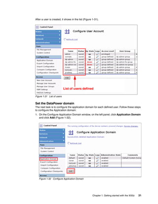
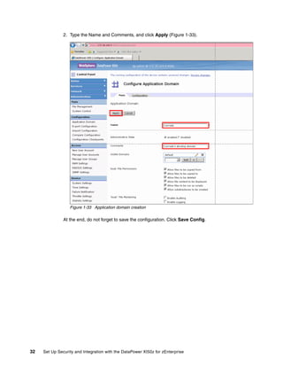
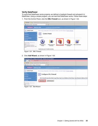
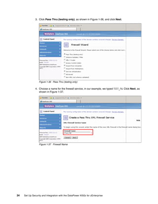
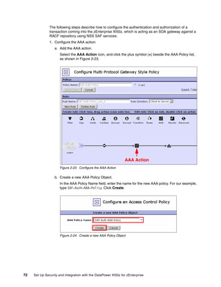
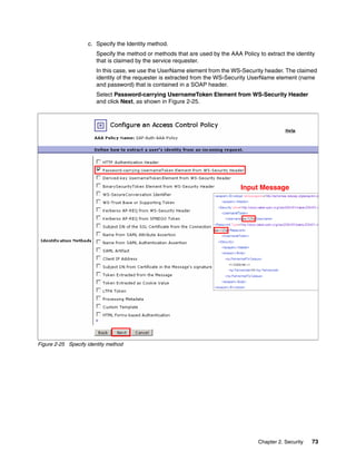
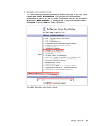
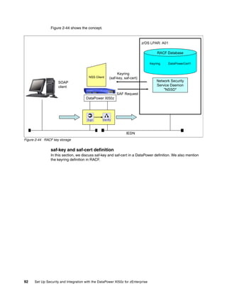
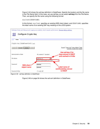
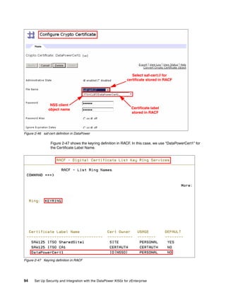
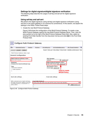
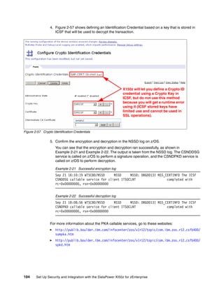
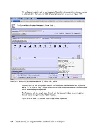
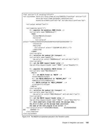
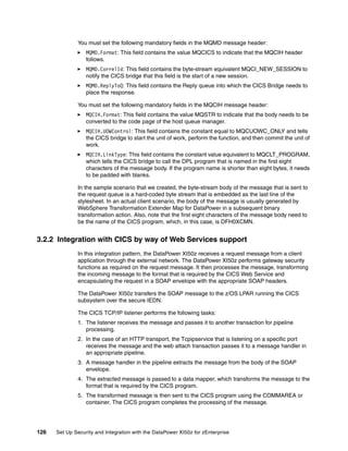
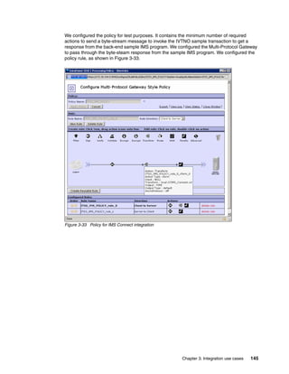
Downloaded 93 times


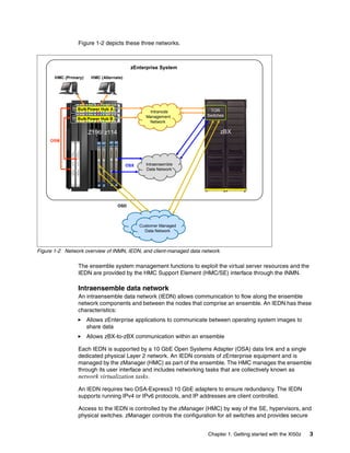

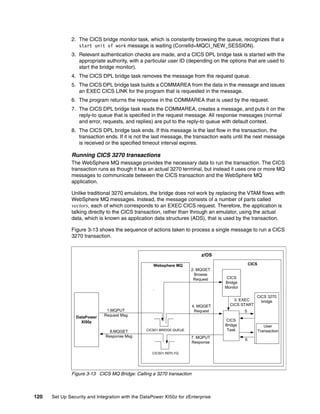

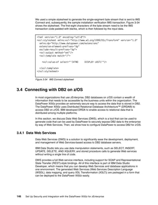


The document provides guidance on setting up security and integration between the IBM DataPower XI50z appliance and IBM zEnterprise systems. It discusses planning the network topology and initial setup of the virtual network. It also covers key security concepts and implementing authentication, authorization, and identity propagation when integrating the XI50z with z/OS mainframe systems like CICS, IMS, DB2 and WebSphere MQ. The document is intended to help users securely connect and integrate the XI50z with various zEnterprise applications and services.


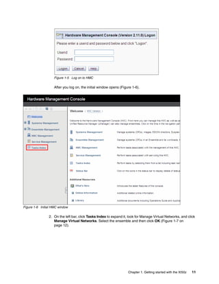
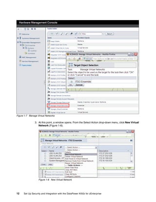
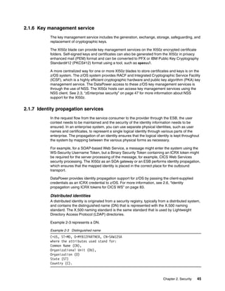
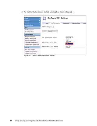
![5G Explained! A High Level Overview [Introduction]](https://cdn.slidesharecdn.com/ss_thumbnails/5gexplainedahighleveloverview-260119165306-cc137a3e-thumbnail.jpg?width=640&height=640&fit=bounds)


