9C106.101 1
Department OfTechnical Education
Andhra Pradesh
Name : J. Ganga Reddy
Designation : Lecturer
Branch : Civil Engineering
Institute : Govt. Polytechnic, Hyderabad
Year/Semester : I Year
Subject : Engineering Mechanics
Subject code : C106
Topic : Shear Force & Bending Moment
Duration : 50 Min
Sub Topic : SFD & BMD for a cantilever subjected to
point loads and UDL
Teaching Aids : PPTs, Animations and Sketches
Revised by : M. Mahesh & J. Ganga Reddy
2.
9C106.101 2
Objectives
On completionof this topic, you will be able to
• Determine shear force
• Determine Bending moment
• Plot S.F. and B.M. values at salient points to draw
shear force diagram (SFD) and bending moment
diagram (BMD)
In the case of a cantilever beam subjected to point loads
and UDL
3.
9C106.101 3
Recap
• SFat any section is the algebraic sum of all the vertical
forces taken either to the left or right of the section
including support reactions
• S.F is taken as positive if it acts towards left in the
upward direction/towards right in the downward direction
• S.F us taken as negative if it acts towards right in the
upward direction/towards left in the downward direction.
4.
9C106.101 4
Recap
• B.Mat any section is defined as the algebraic sum of
moments of all vertical forces acting either to the left or
to the right of the section including those of support
reactions
• B.M causing concavity upwards will be taken as positive
and called as sagging bending moment
• B.M causing convexity upwards will be taken as negative
and called as hogging bending moment.
5.
9C106.101 5
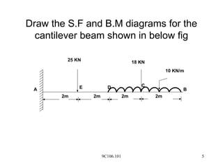
Draw theS.F and B.M diagrams for the
cantilever beam shown in below fig
25 KN 18 KN
10 KN/m
E D
2m 2m 2m 2m
C
B
A
6.
9C106.101 6
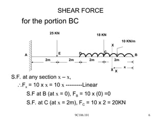
for theportion BC
S.F. at any section x – x,
Fx = 10 x x = 10 x ---------Linear
S.F at B (at x = 0), FB = 10 x (0) =0
S.F. at C (at x = 2m), FC = 10 x 2 = 20KN
25 KN 18 KN
10 KN/m
E D
2m 2m 2m 2m
C
B
A
x
X
X
X
SHEAR FORCE
7.
9C106.101 7
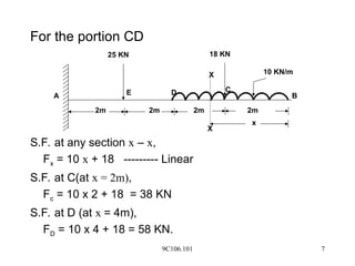
For theportion CD
S.F. at any section x – x,
Fx = 10 x + 18 --------- Linear
S.F. at C(at x = 2m),
Fc = 10 x 2 + 18 = 38 KN
S.F. at D (at x = 4m),
FD = 10 x 4 + 18 = 58 KN.
25 KN 18 KN
10 KN/m
E D
2m 2m 2m 2m
C
B
A
x
X
X
8.
9C106.101 8
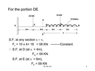
For theportion DE
S.F. at any section x – x,
Fx = 10 x 4+ 18 = 58 KN ---------Constant
S.F. at D (at x = 4m),
FD = 58 KN
S.F. at E (at x = 6m),
FE = 58 KN
25 KN 18 KN
10 KN/m
E D
2m 2m 2m 2m
C
B
A
x
X
X
9.
9C106.101 9
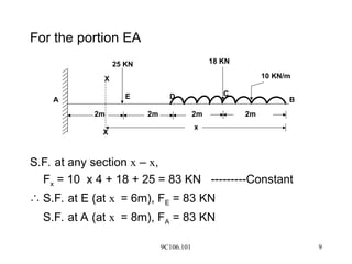
For theportion EA
S.F. at any section x – x,
Fx = 10 x 4 + 18 + 25 = 83 KN ---------Constant
S.F. at E (at x = 6m), FE = 83 KN
S.F. at A (at x = 8m), FA = 83 KN
25 KN 18 KN
10 KN/m
E D
2m 2m 2m 2m
C
B
A
x
X
X
10.
9C106.101 10
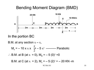
Bending MomentDiagram (BMD)
In the portion BC
B.M. at any section x – x,
Mx = – 10 x x x = – 5 x2
---------- Parabolic
B.M. at B (at x = 0), MB = – 5 (0)2
=0
B.M. at C (at x = 2), Mc = – 5 (2)2
= – 20 KN -m
2
x
25 KN 18 KN
10 KN/m
E D
2m 2m 2m 2m
C
B
A
x
X
X
11.
9C106.101 11
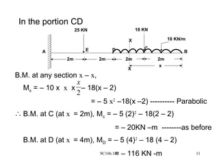
In theportion CD
B.M. at any section x – x,
Mx = – 10 x x x – 18(x – 2)
= – 5 x2
–18(x –2) ---------- Parabolic
B.M. at C (at x = 2m), Mc = – 5 (2)2
– 18(2 – 2)
= – 20KN –m --------as before
B.M. at D (at x = 4m), MD = – 5 (4)2
– 18 (4 – 2)
= – 116 KN -m
2
x
25 KN 18 KN
10 KN/m
E D
2m 2m 2m 2m
C
B
A
x
X
X
12.
9C106.101 12
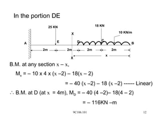
In theportion DE
B.M. at any section x – x,
Mx = – 10 x 4 x (x –2) – 18(x – 2)
= – 40 (x –2) – 18 (x –2) ------ Linear)
B.M. at D (at x = 4m), MD = – 40 (4 –2)– 18(4 – 2)
= – 116KN –m
25 KN 18 KN
10 KN/m
E D
2m 2m 2m 2m
C
B
A
x
X
X
9C106.101 14
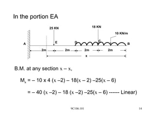
In theportion EA
B.M. at any section x – x,
Mx = – 10 x 4 (x –2) – 18(x – 2) –25(x – 6)
= – 40 (x –2) – 18 (x –2) –25(x – 6) ------ Linear)
25 KN 18 KN
10 KN/m
E D
2m 2m 2m 2m
C
B
A
x
15.
9C106.101 15
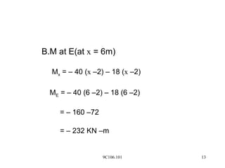
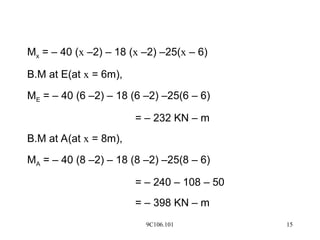
Mx =– 40 (x –2) – 18 (x –2) –25(x – 6)
B.M at E(at x = 6m),
ME = – 40 (6 –2) – 18 (6 –2) –25(6 – 6)
= – 232 KN – m
B.M at A(at x = 8m),
MA = – 40 (8 –2) – 18 (8 –2) –25(8 – 6)
= – 240 – 108 – 50
= – 398 KN – m
16.
9C106.101 16
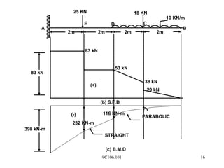
25 KN18 KN
10 KN/m
E D
2m 2m 2m 2m
C
B
A
(-)
232 KN-m
116 KN-m
STRAIGHT
PARABOLIC
398 kN-m
83 kN
83 kN
53 kN
38 kN
20 kN
(+)
(b) S.F.D
(c) B.M.D
17.
9C106.101 17
SUMMARY
In thisclass, it is discussed
• To calculate S.F and B.M at any section
• To draw SFD and BMD
In the case of cantilever subjected to point loads and UDL