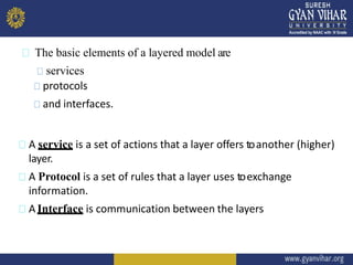
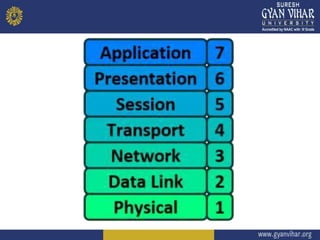
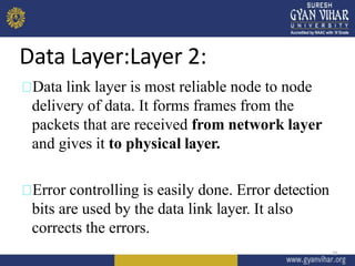
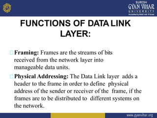
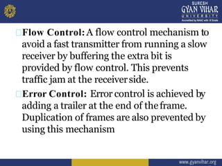
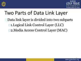
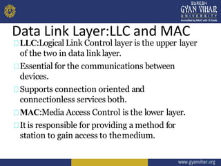
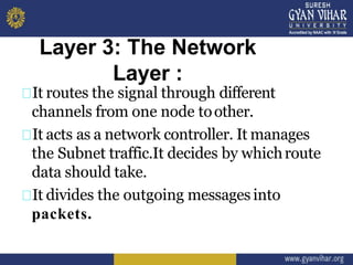
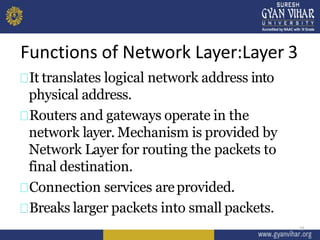
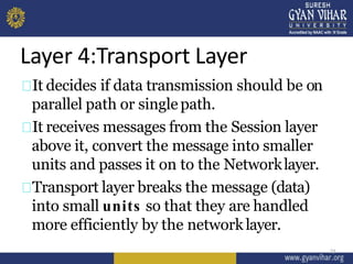
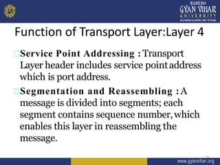
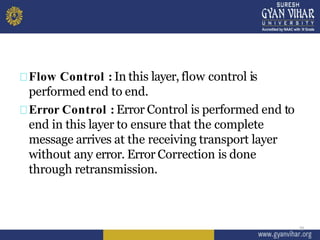
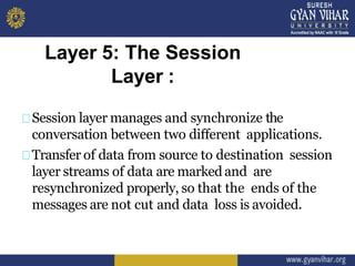
1
DNC (Unit-1)
LECTURE-1
DISTRIBUTED
NETWORK
COMMUNICATION
SOHIT AGARWAL
DEPARTMENT OF COMPUTER ENGINEERING AND INFORMATION TECHNOLOGY
Index
2
1. OSI model & function of each
Layer.
2. TCP/ IP model.
3. Connection oriented v/s
Connectionless approach.
4. Comparison of OSI & TCP/IP
Models.
1.OSI model & function of each Layer.
There are many users who use computer
network and are located all over the world.
For national and worldwide data
communication, systems must be developed
which are compatible to communicate with
each other.
ISO has developed this.
ISO stands for International organization of
Standardization.
This is called a model for Open System
Interconnection (OSI) and is commonly
known as OSI model.
The ISO-OSI model is a seven layer (7
Layer)architecture developed in 1984
4
To reduce the design complexity, most of the
networks are organized as a series of layers or
levels, each one build upon one below it.
The basic idea of a layered architecture is to
divide the design into small pieces.
Each layer adds to the services provided by the
lower layers in such a way that the highest
layer is provided has a full set of services.
5
The basic elements of a layered model are
services
protocols
and interfaces.
A service is a set of actions that a layer offers toanother (higher)
layer.
A Protocol is a set of rules that a layer uses toexchange
information.
A Interface is communication between the layers
7
Layer 1,2and 3that is physical ,data and
network layers are Network Support
Layers.
Layers 5,6 and 7 that is session,presentation
and application layers are User Support
Layer.
Transport Layer links the network support
layers and user support layers.
8
9
Physical Layer:Layer 1
10
Physical layer is the lowest layer of all. It is
responsible for sending bits from one
computer to another. This layer is not
concerned with the meaning of the bitsand
deals with the physical connection to the
network and with transmission.
This layer defines electrical and physical
details represented as 0or a1
Functions of Physical Layer:
11
Representation of Bits: Data in this layer
consists of stream of bits.
Data Rate: This layer defines the rate of
transmission which is the number of bits per
second.
Synchronization: It deals with the
synchronization of the transmitter and receiver.
Interface: The physical layer defines the
transmission interface between devices and
transmission medium.
12
Line Configuration: This layer connects
devices with the medium: Point to Point
configuration and Multipoint configuration.
Topologies: Devices must be connected using
the following topologies: Mesh, Star, Ring
and Bus.
13
Transmission Modes: Physical
Layer defines the direction of
transmission between two
devices: Simplex, Half Duplex,
Full Duplex.
Deals with baseband and broadband
transmission.
14
Data Layer:Layer 2:
15
Data link layer is most reliable node to node
delivery of data. It forms frames from the
packets that are received from network layer
and gives it to physical layer.
Error controlling is easily done. Error detection
bits are used by the data link layer. It also
corrects the errors.
FUNCTIONS OF DATALINK
LAYER:
Framing: Frames are the streams of bits
received from the network layer into
manageable data units.
Physical Addressing: The Data Link layer adds a
header to the frame in order to define physical
address of the sender or receiver of the frame, if the
frames are to be distributed to different systems on
the network.
Flow Control:A flow control mechanism to
avoid a fast transmitter from running a slow
receiver by buffering the extra bit is
provided by flow control. This prevents
traffic jam at the receiverside.
Error Control: Error control is achieved by
adding a trailer at the end of theframe.
Duplication of frames are also prevented by
using this mechanism
Access Control: Protocols of this layer
determine which of the devices hascontrol
over the link at any giventime.
18
Two Parts of Data Link Layer
19
Data link layer is divided into two subparts
1.Logical Link Control Layer (LLC)
2.Media Access Control Layer (MAC)
Data Link Layer:LLC and MAC
LLC:Logical Link Control layer is the upper layer
of the two in data link layer.
Essential for the communications between
devices.
Supports connection oriented and
connectionless services both.
MAC:Media Access Control is the lower layer.
It is responsible for providing a method for
station to gain access to themedium.
21
Layer 3: The Network
Layer :
It routes the signal through different
channels from one node toother.
It acts as a network controller. It manages
the Subnet traffic.It decides by whichroute
data should take.
It divides the outgoing messages into
packets.
Functions of Network Layer:Layer 3
22
It translates logical network address into
physical address.
Routers and gateways operate in the
network layer. Mechanism is provided by
Network Layer for routing the packets to
final destination.
Connection services areprovided.
Breaks larger packets into small packets.
Layer 4:Transport Layer
23
It decides if data transmission should be on
parallel path or singlepath.
It receives messages from the Session layer
above it, convert the message into smaller
units and passes it on to the Networklayer.
Transport layer breaks the message (data)
into small units so that they are handled
more efficiently by the networklayer.
Function of Transport Layer:Layer 4
24
Service Point Addressing : Transport
Layer header includes service pointaddress
which is port address.
Segmentation and Reassembling : A
message is divided into segments; each
segment contains sequence number,which
enables this layer in reassembling the
message.
Flow Control : In this layer, flow control is
performed end to end.
Error Control : Error Control is performed end to
end in this layer to ensure that the complete
message arrives at the receiving transport layer
without any error. Error Correction is done
through retransmission.
25
Layer 5: The Session
Layer :
Session layer manages and synchronize the
conversation between two different applications.
Transfer of data from source to destination session
layer streams of data are marked and are
resynchronized properly, so that the ends of the
messages are not cut and data loss is avoided.
Functions of Session Layer:Layer 5
27
Dialog Control : This layer allows two
systems to start communication witheach
other in half-duplex orfull-duplex.
Synchronization : This layer allows a
process to add checkpoints which are
considered as synchronization points into
stream of data.
Example: If a system is sending a file of 800
pages, adding checkpoints after every 50
pages is recommended. This ensures that 50
page unit is successfully received and
acknowledged. This is beneficial at the time
of crash as if a crash happens at page
number 110; there is no needto retransmit 1
to 100pages.
28
THANK YOU

L 1

  • 1.
  • 2.
    Index 2 1. OSI model& function of each Layer. 2. TCP/ IP model. 3. Connection oriented v/s Connectionless approach. 4. Comparison of OSI & TCP/IP Models.
  • 3.
    1.OSI model &function of each Layer. There are many users who use computer network and are located all over the world. For national and worldwide data communication, systems must be developed which are compatible to communicate with each other. ISO has developed this.
  • 4.
    ISO stands forInternational organization of Standardization. This is called a model for Open System Interconnection (OSI) and is commonly known as OSI model. The ISO-OSI model is a seven layer (7 Layer)architecture developed in 1984 4
  • 5.
    To reduce thedesign complexity, most of the networks are organized as a series of layers or levels, each one build upon one below it. The basic idea of a layered architecture is to divide the design into small pieces. Each layer adds to the services provided by the lower layers in such a way that the highest layer is provided has a full set of services. 5
  • 6.
    The basic elementsof a layered model are services protocols and interfaces. A service is a set of actions that a layer offers toanother (higher) layer. A Protocol is a set of rules that a layer uses toexchange information. A Interface is communication between the layers
  • 7.
  • 8.
    Layer 1,2and 3thatis physical ,data and network layers are Network Support Layers. Layers 5,6 and 7 that is session,presentation and application layers are User Support Layer. Transport Layer links the network support layers and user support layers. 8
  • 9.
  • 10.
    Physical Layer:Layer 1 10 Physicallayer is the lowest layer of all. It is responsible for sending bits from one computer to another. This layer is not concerned with the meaning of the bitsand deals with the physical connection to the network and with transmission. This layer defines electrical and physical details represented as 0or a1
  • 11.
    Functions of PhysicalLayer: 11 Representation of Bits: Data in this layer consists of stream of bits. Data Rate: This layer defines the rate of transmission which is the number of bits per second.
  • 12.
    Synchronization: It dealswith the synchronization of the transmitter and receiver. Interface: The physical layer defines the transmission interface between devices and transmission medium. 12
  • 13.
    Line Configuration: Thislayer connects devices with the medium: Point to Point configuration and Multipoint configuration. Topologies: Devices must be connected using the following topologies: Mesh, Star, Ring and Bus. 13
  • 14.
    Transmission Modes: Physical Layerdefines the direction of transmission between two devices: Simplex, Half Duplex, Full Duplex. Deals with baseband and broadband transmission. 14
  • 15.
    Data Layer:Layer 2: 15 Datalink layer is most reliable node to node delivery of data. It forms frames from the packets that are received from network layer and gives it to physical layer. Error controlling is easily done. Error detection bits are used by the data link layer. It also corrects the errors.
  • 16.
    FUNCTIONS OF DATALINK LAYER: Framing:Frames are the streams of bits received from the network layer into manageable data units. Physical Addressing: The Data Link layer adds a header to the frame in order to define physical address of the sender or receiver of the frame, if the frames are to be distributed to different systems on the network.
  • 17.
    Flow Control:A flowcontrol mechanism to avoid a fast transmitter from running a slow receiver by buffering the extra bit is provided by flow control. This prevents traffic jam at the receiverside. Error Control: Error control is achieved by adding a trailer at the end of theframe. Duplication of frames are also prevented by using this mechanism
  • 18.
    Access Control: Protocolsof this layer determine which of the devices hascontrol over the link at any giventime. 18
  • 19.
    Two Parts ofData Link Layer 19 Data link layer is divided into two subparts 1.Logical Link Control Layer (LLC) 2.Media Access Control Layer (MAC)
  • 20.
    Data Link Layer:LLCand MAC LLC:Logical Link Control layer is the upper layer of the two in data link layer. Essential for the communications between devices. Supports connection oriented and connectionless services both. MAC:Media Access Control is the lower layer. It is responsible for providing a method for station to gain access to themedium. 21
  • 21.
    Layer 3: TheNetwork Layer : It routes the signal through different channels from one node toother. It acts as a network controller. It manages the Subnet traffic.It decides by whichroute data should take. It divides the outgoing messages into packets.
  • 22.
    Functions of NetworkLayer:Layer 3 22 It translates logical network address into physical address. Routers and gateways operate in the network layer. Mechanism is provided by Network Layer for routing the packets to final destination. Connection services areprovided. Breaks larger packets into small packets.
  • 23.
    Layer 4:Transport Layer 23 Itdecides if data transmission should be on parallel path or singlepath. It receives messages from the Session layer above it, convert the message into smaller units and passes it on to the Networklayer. Transport layer breaks the message (data) into small units so that they are handled more efficiently by the networklayer.
  • 24.
    Function of TransportLayer:Layer 4 24 Service Point Addressing : Transport Layer header includes service pointaddress which is port address. Segmentation and Reassembling : A message is divided into segments; each segment contains sequence number,which enables this layer in reassembling the message.
  • 25.
    Flow Control :In this layer, flow control is performed end to end. Error Control : Error Control is performed end to end in this layer to ensure that the complete message arrives at the receiving transport layer without any error. Error Correction is done through retransmission. 25
  • 26.
    Layer 5: TheSession Layer : Session layer manages and synchronize the conversation between two different applications. Transfer of data from source to destination session layer streams of data are marked and are resynchronized properly, so that the ends of the messages are not cut and data loss is avoided.
  • 27.
    Functions of SessionLayer:Layer 5 27 Dialog Control : This layer allows two systems to start communication witheach other in half-duplex orfull-duplex. Synchronization : This layer allows a process to add checkpoints which are considered as synchronization points into stream of data.
  • 28.
    Example: If asystem is sending a file of 800 pages, adding checkpoints after every 50 pages is recommended. This ensures that 50 page unit is successfully received and acknowledged. This is beneficial at the time of crash as if a crash happens at page number 110; there is no needto retransmit 1 to 100pages. 28
  • 29.