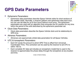
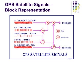
Simulation Study, Analysis and 
Development of 
Improved Navigation Solution for GPS 
PPrreesseennttaattiioonn##33 
Amit Katti 08D91A0408 
Sandeep Patil 08D91A0488 
Sainath Reddy 08D91A04A4 
A.Katti, S.Patil & S.Reddy
Recap 
 GPS Overview 
 Position and Time from GPS 
 C/A and Pseudorange Navigation 
And now, the leap… 
A.Katti, S.Patil & S.Reddy
Simplified GPS Receiver 
A.Katti, S.Patil & S.Reddy
GPS Data Parameters 
A.Katti, S.Patil & S.Reddy 
 Ephemeris Parameters: 
 Ephemeris data parameters describe Space Vehicle orbits for short sections of 
the satellite orbits. Normally, a receiver gathers new ephemeris data each hour, 
but can use old data for up to four hours without much error. The ephemeris 
parameters are used with an algorithm that computes the SV position for any time 
within the period of the orbit described by the ephemeris parameter set. 
 Clock Data Parameters: 
 Clock data parameters describe the Space Vehicle clock and its relationship to 
GPS time. 
 Almanac Parameters: 
 Almanacs are approximate orbital data parameters for all Space Vehicles. 
 UTC & Ionospheric Parameters: 
 Each SV sends the amount to which GPS Time is offset from Universal 
Coordinated Time. This correction can be used by the receiver to set UTC to 
within 100 ns. 
 Each complete SV data set includes an ionospheric model that is used in the 
receiver to approximates the phase delay through the ionosphere at any location 
and time.
GPS Satellite Signals – 
Block Representation 
A.Katti, S.Patil & S.Reddy
A.Katti, S.Patil & S.Reddy 
Gold Code 
 The PRN sequences, Gi (t) and Pi (t), used by the satellites are 
called Gold codes. The Gold codes have a very high bandwidth and 
are used to spread the spectrum of the data message over a much 
wider bandwidth. In the receiver, the spreading effect of the PRN 
sequences is removed by using locally generated replicas of the 
broadcast Gold codes. Each satellite transmits its own unique Gold 
code and the user receives multiple satellite signals at nearly the 
same frequency.
The Gold Code, Contd… 
 The C/A Gold codes are transmitted at a chipping rate of 
1.023 Mbps. The individual symbols of the codes are 
referred to as chips, as opposed to the bits of the 
navigation message. A code g(t) is originally generated 
as a binary sequence and is used to modulate the phase 
of the carrier signal, as given in the equation below. 
A.Katti, S.Patil & S.Reddy
GPS Data Frame 
A.Katti, S.Patil & S.Reddy
GPS Data Format 
A.Katti, S.Patil & S.Reddy
Pseudorange Navigation 
 The position of the receiver is where the pseudo-ranges 
from a set of SVs intersect. Position is determined from 
multiple pseudo-range measurements at a single 
measurement epoch. The pseudo range measurements 
are used together with SV position estimates based on 
the precise orbital elements (the ephemeris data) sent by 
each SV. This orbital data allows the receiver to compute 
the SV positions in three dimensions at the instant that 
they sent their respective signals. 
A.Katti, S.Patil & S.Reddy
Pseudorange Navigation 
A.Katti, S.Patil & S.Reddy
ECEF Coordinate System 
A.Katti, S.Patil & S.Reddy
Carrier Phase Tracking 
A.Katti, S.Patil & S.Reddy
GPS Carrier Phase Positioning 
A.Katti, S.Patil & S.Reddy
Software Approach 
 The first task of any receiver is to determine which satellites are in 
view. After determining that a given satellite signal is available, the 
receiver attempts to track the carrier and PRN components of the 
signal. 
 A traditional receiver uses a Costas loop to track the carrier and a 
Delay-Lock Loop to track the PRN sequence. Using the output of 
the tracking loops, the navigation message for each satellite is 
decoded. 
 The navigation message provides the user with enough information 
to calculate the positions of the satellites. The User can thereby, 
calculate his position using the pseudo-range measurements from 
the tracking loops. 
A.Katti, S.Patil & S.Reddy
Why Software Approach? 
 Minimum Hardware Use. 
 Flexible 
 Single program can be used to digitalize more than 1 
frequency. 
 New algorithms can easily be developed without 
changing the design of hardware. 
A.Katti, S.Patil & S.Reddy
Front-End GPS Receiver 
A.Katti, S.Patil & S.Reddy
Code Acquisition 
A.Katti, S.Patil & S.Reddy
Tracking Loops 
 Phase Locked Loop 
 Costas Loop 
 Delay Locked Loop 
A.Katti, S.Patil & S.Reddy
Position Determination 
 Least Squares Estimation 
 Kalman Filtering 
A.Katti, S.Patil & S.Reddy 
 Linear KF 
 Extended KF
The Linear Kalman Filter 
The Kalman filter has the capacity to overcome the drawbacks of 
the traditional tracking loop. The Kalman filter is, in essence, a filter 
with time varying gains. The gains vary with changing measurement 
noise statistics and process noise statistics. The measurement 
noise statistics change with C/No levels and jamming. 
The process noise statistics change with user dynamics. Provided 
with the process and measurement noise covariance matrices, the 
Kalman filter can optimally separate signal from noise. The tasks of 
tracking the carrier and code can be combined in one Kalman filter, 
which replaces the two tracking loops in each channel with a single 
Kalman filter per satellite. 
A.Katti, S.Patil & S.Reddy
How does the KF Work? 
 The Kalman filter used to track the carrier and code is similar to 
the filter used to track the user’s position. 
 The measurements provided to the filter are not measurements 
of the states directly, but rather the errors between certain states 
and those of the received signal. 
 The measurements are therefore residuals. The filter has access 
to three residuals, which are measurements of the error in the 
phase and frequency of the carrier, and the error in the phase of 
the local Gold code. 
A.Katti, S.Patil & S.Reddy
KF Working - Algorithm 
A.Katti, S.Patil & S.Reddy
State Transition Matrix 
A.Katti, S.Patil & S.Reddy 
θc,k+1 = IF Carrier 
Phase 
fc,k+1 = Second State 
Derivative of IF 
Carrier Phase 
f’c,k+1 = Varying Bias – 
Third State 
θG,k+1= Local Gold 
Code Phase
Extended KF Transition Matrix 
A.Katti, S.Patil & S.Reddy
States of a Kalman Filter 
 Position Error 
 Velocity Error 
 GPS Receiver Clock Bias 
 Clock Drift 
A.Katti, S.Patil & S.Reddy
States of a Kalman Filter 
 Apriori State or Pre-Prior State 
 Kalman Gain 
 Covariance Error Matrix 
 Noise Elimination 
A.Katti, S.Patil & S.Reddy
MATLAB® Results for the 
Kalman Filter 
 Vehicle Position 
 Position Measurement and Estimation Error 
 True & Estimated Velocity 
 Velocity Estimation Error 
A.Katti, S.Patil & S.Reddy
Why is KF Better than other 
methods? 
 The main advantage of the information filter is that N measurements 
can be filtered at each time-step simply by summing their 
information matrices and vectors. 
 The Kalman filter operates recursively on streams of noisy input 
data to produce a statistically optimal estimate of the underlying 
system state. 
 Because of the algorithm's recursive nature, it can run in real time 
using only the present input measurements and the previously 
calculated state; no additional past information is required. 
A.Katti, S.Patil & S.Reddy
Applications of KF 
 Satellite Navigation Systems 
 Auto-Pilot 
 Brain-Computer Interface 
 3D Modeling 
 Radar Tracker 
 Tracking of objects in Computer Vision 
 Altitude and Heading Reference Systems 
A.Katti, S.Patil & S.Reddy
A.Katti, S.Patil & S.Reddy 
Conclusion 
 We took up this project as a part of the thesis because of 
our immense interest towards Satellite Communication 
Systems. 
 We thank Mr. G Srinivasa Rao, the internal guide for his 
excellent guidance and presentation strategy. 
 We also thank all other faculty members and the project 
coordinators to have helped us throughout.

Undergrad Senior Design Thesis

  • 1.
    Simulation Study, Analysisand Development of Improved Navigation Solution for GPS PPrreesseennttaattiioonn##33 Amit Katti 08D91A0408 Sandeep Patil 08D91A0488 Sainath Reddy 08D91A04A4 A.Katti, S.Patil & S.Reddy
  • 2.
    Recap  GPSOverview  Position and Time from GPS  C/A and Pseudorange Navigation And now, the leap… A.Katti, S.Patil & S.Reddy
  • 3.
    Simplified GPS Receiver A.Katti, S.Patil & S.Reddy
  • 4.
    GPS Data Parameters A.Katti, S.Patil & S.Reddy  Ephemeris Parameters:  Ephemeris data parameters describe Space Vehicle orbits for short sections of the satellite orbits. Normally, a receiver gathers new ephemeris data each hour, but can use old data for up to four hours without much error. The ephemeris parameters are used with an algorithm that computes the SV position for any time within the period of the orbit described by the ephemeris parameter set.  Clock Data Parameters:  Clock data parameters describe the Space Vehicle clock and its relationship to GPS time.  Almanac Parameters:  Almanacs are approximate orbital data parameters for all Space Vehicles.  UTC & Ionospheric Parameters:  Each SV sends the amount to which GPS Time is offset from Universal Coordinated Time. This correction can be used by the receiver to set UTC to within 100 ns.  Each complete SV data set includes an ionospheric model that is used in the receiver to approximates the phase delay through the ionosphere at any location and time.
  • 5.
    GPS Satellite Signals– Block Representation A.Katti, S.Patil & S.Reddy
  • 6.
    A.Katti, S.Patil &S.Reddy Gold Code  The PRN sequences, Gi (t) and Pi (t), used by the satellites are called Gold codes. The Gold codes have a very high bandwidth and are used to spread the spectrum of the data message over a much wider bandwidth. In the receiver, the spreading effect of the PRN sequences is removed by using locally generated replicas of the broadcast Gold codes. Each satellite transmits its own unique Gold code and the user receives multiple satellite signals at nearly the same frequency.
  • 7.
    The Gold Code,Contd…  The C/A Gold codes are transmitted at a chipping rate of 1.023 Mbps. The individual symbols of the codes are referred to as chips, as opposed to the bits of the navigation message. A code g(t) is originally generated as a binary sequence and is used to modulate the phase of the carrier signal, as given in the equation below. A.Katti, S.Patil & S.Reddy
  • 8.
    GPS Data Frame A.Katti, S.Patil & S.Reddy
  • 9.
    GPS Data Format A.Katti, S.Patil & S.Reddy
  • 10.
    Pseudorange Navigation The position of the receiver is where the pseudo-ranges from a set of SVs intersect. Position is determined from multiple pseudo-range measurements at a single measurement epoch. The pseudo range measurements are used together with SV position estimates based on the precise orbital elements (the ephemeris data) sent by each SV. This orbital data allows the receiver to compute the SV positions in three dimensions at the instant that they sent their respective signals. A.Katti, S.Patil & S.Reddy
  • 11.
  • 12.
    ECEF Coordinate System A.Katti, S.Patil & S.Reddy
  • 13.
    Carrier Phase Tracking A.Katti, S.Patil & S.Reddy
  • 14.
    GPS Carrier PhasePositioning A.Katti, S.Patil & S.Reddy
  • 15.
    Software Approach The first task of any receiver is to determine which satellites are in view. After determining that a given satellite signal is available, the receiver attempts to track the carrier and PRN components of the signal.  A traditional receiver uses a Costas loop to track the carrier and a Delay-Lock Loop to track the PRN sequence. Using the output of the tracking loops, the navigation message for each satellite is decoded.  The navigation message provides the user with enough information to calculate the positions of the satellites. The User can thereby, calculate his position using the pseudo-range measurements from the tracking loops. A.Katti, S.Patil & S.Reddy
  • 16.
    Why Software Approach?  Minimum Hardware Use.  Flexible  Single program can be used to digitalize more than 1 frequency.  New algorithms can easily be developed without changing the design of hardware. A.Katti, S.Patil & S.Reddy
  • 17.
    Front-End GPS Receiver A.Katti, S.Patil & S.Reddy
  • 18.
    Code Acquisition A.Katti,S.Patil & S.Reddy
  • 19.
    Tracking Loops Phase Locked Loop  Costas Loop  Delay Locked Loop A.Katti, S.Patil & S.Reddy
  • 20.
    Position Determination Least Squares Estimation  Kalman Filtering A.Katti, S.Patil & S.Reddy  Linear KF  Extended KF
  • 21.
    The Linear KalmanFilter The Kalman filter has the capacity to overcome the drawbacks of the traditional tracking loop. The Kalman filter is, in essence, a filter with time varying gains. The gains vary with changing measurement noise statistics and process noise statistics. The measurement noise statistics change with C/No levels and jamming. The process noise statistics change with user dynamics. Provided with the process and measurement noise covariance matrices, the Kalman filter can optimally separate signal from noise. The tasks of tracking the carrier and code can be combined in one Kalman filter, which replaces the two tracking loops in each channel with a single Kalman filter per satellite. A.Katti, S.Patil & S.Reddy
  • 22.
    How does theKF Work?  The Kalman filter used to track the carrier and code is similar to the filter used to track the user’s position.  The measurements provided to the filter are not measurements of the states directly, but rather the errors between certain states and those of the received signal.  The measurements are therefore residuals. The filter has access to three residuals, which are measurements of the error in the phase and frequency of the carrier, and the error in the phase of the local Gold code. A.Katti, S.Patil & S.Reddy
  • 23.
    KF Working -Algorithm A.Katti, S.Patil & S.Reddy
  • 24.
    State Transition Matrix A.Katti, S.Patil & S.Reddy θc,k+1 = IF Carrier Phase fc,k+1 = Second State Derivative of IF Carrier Phase f’c,k+1 = Varying Bias – Third State θG,k+1= Local Gold Code Phase
  • 25.
    Extended KF TransitionMatrix A.Katti, S.Patil & S.Reddy
  • 26.
    States of aKalman Filter  Position Error  Velocity Error  GPS Receiver Clock Bias  Clock Drift A.Katti, S.Patil & S.Reddy
  • 27.
    States of aKalman Filter  Apriori State or Pre-Prior State  Kalman Gain  Covariance Error Matrix  Noise Elimination A.Katti, S.Patil & S.Reddy
  • 28.
    MATLAB® Results forthe Kalman Filter  Vehicle Position  Position Measurement and Estimation Error  True & Estimated Velocity  Velocity Estimation Error A.Katti, S.Patil & S.Reddy
  • 29.
    Why is KFBetter than other methods?  The main advantage of the information filter is that N measurements can be filtered at each time-step simply by summing their information matrices and vectors.  The Kalman filter operates recursively on streams of noisy input data to produce a statistically optimal estimate of the underlying system state.  Because of the algorithm's recursive nature, it can run in real time using only the present input measurements and the previously calculated state; no additional past information is required. A.Katti, S.Patil & S.Reddy
  • 30.
    Applications of KF  Satellite Navigation Systems  Auto-Pilot  Brain-Computer Interface  3D Modeling  Radar Tracker  Tracking of objects in Computer Vision  Altitude and Heading Reference Systems A.Katti, S.Patil & S.Reddy
  • 31.
    A.Katti, S.Patil &S.Reddy Conclusion  We took up this project as a part of the thesis because of our immense interest towards Satellite Communication Systems.  We thank Mr. G Srinivasa Rao, the internal guide for his excellent guidance and presentation strategy.  We also thank all other faculty members and the project coordinators to have helped us throughout.