SlideShare a Scribd company logo
Abid H syed Dept.E&CBLDACET
Radio resource management and Mobility management
Radio resource management(RRM) deals with system level management of co-channel
interference, radio resources and other radio related transmission characteristics in wireless
enviroment. It concerns multi-user and multi-cell network capacity issues.The end to end
connectivity is accomplished through the bearer services architechure as shown in fig1.
Example:cellular networks,wireless local area networks,wireless sensorsystems, and radio
Broadcasting.
Fig1:Beare services architechure
Static radio resource management
SRRM involves manual as well as computer-aided fixed cell planning
Ex:
 Frequency allocation band plans decided by standardization bodies
 Deployment of base station sites (or broadcasting transmitter site)
 Examples:
 Antenna heights
 Channel frequency plans
 Sector antenna directions
 Selection ofmodulationandchannel codingparameters
 Circuit mode communication usingFDMAandTDMA.
 Fixed channel allocation(FCA)
 Static handover criteria
Dynamic radio resource management
Dynamic RRM schemes adaptively adjust the radio network parameters to the traffic load, user
positions, user mobility, quality of service requirements, base station density, etc.
 Power control algorithms
Precodingalgorithms
Link adaptationalgorithms
Abid H syed Dept.E&CBLDACET
Dynamic Channel Allocation(DCA) orDynamic Frequency Selection(DFS) algorithms, allowing
"cell breathing"
Traffic adaptivehandovercriteria, allowing "cell breathing"
Re-use partitioning
 Adaptive filtering
 Single Atenna interference cancellation(SAIC)
Dynamicdiversity schemes, for example
Soft handover
Dynamic single-frequency networks(DSFN)
 Phased array antenna with beamforing
Multiple-input multiple-output communications(MIMO)
Space-time coding
Admission control
PDCP
Packet Data Convergence Protocol(PDCP), is specified by 3GPP for LTE 5G New Radio (NR).
The PDCP is located in the Radio Protocol Stack in the UMTS/LTE/5G, air interface on top of the
RLC layer as shown in figure2 .
PDCP provides its services to the RRC and user plane upper layers.
e.g. IP at the UE or relay at the base station.
Following services are provided by PDCP to upper layers:
Transfer of user plane data
Transfer of control plane data
Header compression
Ciphering
Integrity protection
The header compression technique is based on either IP header compression (RFC 2507) or Robust Header
Compression(RFC 3095). If PDCP is configured for No Compression, it will send the IP Packets without
compression; otherwise it will compress the packets according to its configuration by upper layer and attach a
PDCP header and send the packet.
Abid H syed Dept.E&CBLDACET
Overview
Figure2:PDCP, located in the Radio Protocol Stack on top of the RLC layer
Radio link control (RLC)
RLC is a layer 2 Radio link control used in UMTS and LTE on the air interface. It’s is specified by
3GPP for UMTS/LTE and for TS (in 5G)New Radio (NR). RLC is located on top of the 3GPP
MAC-layer and below the PDCP-layer. The main function of the RLC protocol are:
Transfer of upper layer Protocol Data Units (PDUs) in one of three modes: Acknowledged Mode
(AM), Unacknowledged Mode (UM) and Transparent Mode (TM)
Error correction through ARQ(only for AM data transfer)
Concatenation, segmentation and reassembly of RLC SDUs (UM and AM)
Re-segmentation of RLC data PDUs (AM)
Reordering of RLC data PDUs (UM and AM);
Duplicate detection (UM and AM);
RLC SDU discard (UM and AM)
RLC re-establishment
Protocol error detection and recovery
Abid H syed Dept.E&CBLDACET
PDU headers and formats
A protocol data unit(PDU) is a single unit of information transmitted among peer entities of
acomputer network. A PDU is composed of protocol-specific control information and user data as
shown in fig3
Fig3:Formats of RLC Data PDU
The RLC have the fallowing fields:
Framing Info(FI) field:Indiactes wether RLC SDU is segmented at the begining and/or end of data
field
Length field(LI): Indiactes length in bytes of corresponding data.
Extension bit field(E): Whether a data field follows or a set of E-field.
SN field:It indiactes the sequence no of corresponding UMD or AMD PDU
RLC Modes: RLC has got the fallowing modes.
Transparent Mode
• No segmentation and reassembly of RLC SDUs • No RLC headers are added • No delivery
guarantees • Suitable for carrying voice
Unacknowledged Mode
• Segmentation and reassembly of RLC SDUs • RLC Headers are added • No delivery guarantees •
Suitable for carrying streaming traffic
Acknowledged Mode
• Segmentation and reassembly of RLC SDUs • RLC Headers are added • Reliable in sequence
delivery service • Suitable for carrying TCP traffic
Abid H syed Dept.E&CBLDACET
LTE MAC PDU is a bit string but octet aligned (i.e multiple of 8 bits). A MAC PDU header consists
of one or more subheaders. Each subheader corresponds to either a MAC SDU, MAC control
element or padding.MAC PDU header can have these six elements R/R/E/LCID/F/L. The last
subheader in MAC PDU and subheaders for MAC control elements consists solely of four elements
R/R/E/LCID. A MAC PDU subheader corresponding to padding consists of the four header fields
R/R/E/LCID.Here are some of the guidelines followed when multiple subheaders need to be present
in a single MAC PDU
MAC PDU subheaders have the same order as MAC SDUs, MAC control elements and padding
MAC control elements always placed before MAC SDU.
Padding occurs at the end of MAC PDU except when single byte or two bytes padding required.
When single-byte or two-byte padding is required, one or two MAC PDU subheaders corresponding
to padding are placed at the beginning of the MAC PDU before any other MAC PDU subheader.
A maximum of one MAC PDU can be transmitted per TB per UE. A maximum of one MCH MAC
PDU can be transmitted per TTI as shown in fig4.
Figure4:MAC PDU
Radio Resource Control(RRC)
RRC protocol is used in UMTS and LTE on the air interface. It is a layer that exists between UE
and eNB and exists at the IP level (Layer 3/Network Layer). This protocol is specified by3GPPi in
TS 36.331 for LTE. RRC messages are transported via thePDCP-Protocol.
Functions of the RRC
 Connection establishment and release functions
 Broadcast of system information
Abid H syed Dept.E&CBLDACET
 Radio bearer establishment, reconfiguration and release
 RRC connection mobility procedures
 Paging notification and release and outer loop power control
Fig5:PDCP data PDU format for user plane and control plane
RRC overview
RRC has got only two states :i.RRC_idle ii.RRC_connected as shown in fig6.A UE is in the
RRC CONNECTED state when an “RRC_connected” connection, has been established otherwise
it’s in the IDLEstate.
Fig6:RRC states
Functions
IDLEstate: RRC CONNECTED
UE controlled mobility Unicast data transfer
Paging
Broadcast of system
information
Network controlled
mobility
Paging
Broadcast of system
information
Abid H syed Dept.E&CBLDACET
Mobility Management Entity
Mobility Management Entity (MME) is responsible for the mobility management function. The
MME is connected to a large number of evolved Node Bs (cells) as shown in fig7. They are
grouped into the Tracking Areas (TAs). The TAs are further grouped into TA Lists (TALs). When a
User Equipment (UE) moves out of the current TAL, it reports its new location to the MME. If the
LTE network attempts to connect to the UE, the MME asks the cells in the TAL to page the UE. In
LTE paging, the MME may se-quentially page a cell, the TA of the cell, and/or TAL of the cell. The
performance of paging and the guidelines for the best paging sequence of cells.
Fig7:MME connected to e_NodeBs
S1 mobility: S1 mobility is semilar to UMTS serving radio network subsystem(SRNS).It consists
of fallowing steps,as shown in fig8.
Fig8:S1 interface signal flow
Abid H syed Dept.E&CBLDACET
1. Preparation Phase : A target MME and eNode-B is identified when decision for a handover
is taken. The network has to allocate resources to target side for the impending handover . The
MME sends a handover request to the target eNode-B requesting it to set up the appropriate
resources for the UE . Once resources have been allocated at the target eNode-B , it sends a
handover request ACK to the MME . Once this message is received by the MME , it sends a
handover command to the UE via the source eNode-B .
2 . Execution Phase :After receiving the handover command, the UE responds by performing the
various RAN related procedures needed for the handover including accessing the target
eNode-B, using the Random Access Channel (RACH) .While the UE performes the
handover , the source eNode-B initiates the status transfer where the PDCP context of the
UE is transfered to the target eNode-B . The source eNode-B also forwards the data stored
in PDCP buffer to the target eNode-B . Once the status and the data have been transfered
to the target eNode-B and the UE is able to establish a Radio Access Bearer (RAB) on
the target eNode-B , it sends the handover confirm message to the target eNode-B.
3 . Completion Phase : When the target eNode-B receives the handover confirm message ,
it sends a handover notify message to the MME. The MME then informs the source
eNode-B to release the resources originally used by the UE.
X2 mobility: It’s the default mode of operation, unless X2 mode is not avialable between source
and target eNode-Bs.
Fig9:X2 interface signal flow
Abid H syed Dept.E&CBLDACET
It has got the fallowing phases.
1.Preparation phase: Handover decision is made by the source eNode-B , it sends a
handover request message to the target eNode-B.On recieving this message,the target eNode-B
works with the MME and S-GW to set up the resources for the UE . In the case of
mobility over X2 Interface , it is possible to set up resources on a per-RAB(radio access
bearer) basis, which implies that upon the completion of the handover, the UE will have
the same RABs at the target eNode-B with the same set of QoS as it had on the source
eNode-B . This process makes the handover quick and seamless and the UE is not
required to set up the RAB with the target eNode-B once the handover is completed . The
target eNode-B responds to the source eNode-B with a handover request ACK once it is
ready .
2 . Execution Phase : Upon receiving the handover request ACK , the source eNode-B
sends a handover command to the UE . While the UE completes the various RAN-related
Handover procedures , the source eNode-B starts the status and data transfer to the target
eNode-B . This is done on a per-RAB basis for the UE .
3 . Completion Phase : Once the UE completes the handover procedure , it sends a handoff
complete message to the target eNode-B . Then the target eNode-B sends a path switch
request to the MME / S-GW and the S-GW switches the GTP tunnel to the source eNode-
B to the target eNode-B .When the data path in the user plane is switched , the target
eNode-B sends a message to the source eNode-B to release the resources originally used
by the UE.
Inter-Cell Interference Coordination
Downlink
Inter-cell interference management is one of the most performance limiting factor.Inter-Cell
Interference Coordination(ICIC) techniques, present a solution by applying restrictions to the
RRM block, improving favorable channel conditions across subsets of users that are severely
impacted by the interference, and thus attaining high spectral efficiency.
The basic approaches for downlink ICI mitigation are as follows :
ICI randomization
In interference randomization, the user’s data are spread over a distributed set of subcarriers so that
interference scenario can be randomized and frequency diversity gain can be achieved. In each cell
the user’s data are sequentially allocated over a time-frequency chunks. When all the requested
transmission are allocated, subcarriers permutation is made in random manner so that each UE’s
transmission is arbitrarily spread up over the total time-frequency grid. Fig.10 shows the allocation
Abid H syed Dept.E&CBLDACET
of subcarriers in a given cell before and after the pseudorandom permutation. In each interfering
cell, the pseudorandom permutation is performed independently. The cell specific scrambling
causes the interference spread up along with the transmission of a given user. As the coding is
performed at the transmitter during transmission, the whole bit stream can be easily recovered at the
receiving end. As interference system requires no signalling overhead for coordination among cells
and less complex resource management, it is suitable for practical system.
Fig10: Subcarrier allocation before (a) and after (b) random permutation
ICI cancellation
If UE is capable of decoding the interfering signals then UE can cancel it,using a multi user
detector.
ICI coordination / avoidance : This is achieved by restrictions to the downlink resource
management in a coordinated way between neighbouring cells .The restrictions can be on
time / frequency resources or transmit power used at each eNode-B . It requires additional
inter-eNode-B communication and UE measurements and reporting .
Static ICI coordination / avoidance : This is mainly done during the cell planning process
and does not require frequent reconfiguration . Ex: static Fractional Frequency Reuse (SFFR) .
Static coordination strategy requires no or little inter eNode-B signaling, but there is
performance limitation as dynamic characteristics such as cell loading or user distributions
are not taken into consideration .
Semi- Static ICI coordination/avoidance : Semi-static coordination typically requires
configurations on a time-scale of the order of seconds or longer , and inter-eNode-B
communication over X2 interface is needed . The information exchanged between
neighbouring eNode-Bs can be transmission power and / or traffic load on different resource
blocks . By considering such information at neighbouring eNode-Bs , ICI suppression is more
efficient .
Abid H syed Dept.E&CBLDACET
Uplink
The basic approaches for uplink ICI mitigation are as follows :
ICI randomization : Similar to the downlink , ICI randomization in the uplink is achieved
by scrambling the encoded symbols prior modulation . Instead of cell-specific scrambling
as used in the downlink , UE-specific scrambling is used in the uplink as ICI comes from
multiple UE’s in neighbouring cells .
ICI cancellation : ICI cancellation is more applicable in the uplink than in the downlink
, as the eNode-B has higher computation capability and usually more antenna elements.
Uplink power control : Power control is an efficient way to suppress ICI in the uplink.
Fractional Power Control (FPC) is used in LTE.
ICI coordination / avoidance : Similar coordination techniques discussed for downlink can
be applied in the uplink , such as FFR.

More Related Content

What's hot

Lte imp
Lte impLte imp
03 umts radio path and transmissionnew
03 umts radio path and transmissionnew03 umts radio path and transmissionnew
03 umts radio path and transmissionnew
sivakumar D
 
LTE RADIO PROTOCOLS
LTE RADIO PROTOCOLSLTE RADIO PROTOCOLS
LTE RADIO PROTOCOLS
brkavyashree
 
02 tm51172 en02gla2_air interface protocols_ppt
02 tm51172 en02gla2_air interface protocols_ppt02 tm51172 en02gla2_air interface protocols_ppt
02 tm51172 en02gla2_air interface protocols_ppt
Ndukwe Amandi
 
Wc & lte 4 g module 4- 2019 by prof.sv1
Wc & lte 4 g  module 4- 2019 by prof.sv1Wc & lte 4 g  module 4- 2019 by prof.sv1
Wc & lte 4 g module 4- 2019 by prof.sv1
SURESHA V
 
Lte phy fundamentals
Lte phy fundamentalsLte phy fundamentals
Lte phy fundamentalsderejew
 
3 lte mac_rrc(조봉열)
3 lte mac_rrc(조봉열)3 lte mac_rrc(조봉열)
3 lte mac_rrc(조봉열)
Dattaraj Pangam
 
Lte system signaling procedures
Lte system signaling proceduresLte system signaling procedures
Lte system signaling procedures
tharinduwije
 
WC and LTE 4G module 1- 2019 by Prof. Suresha V
WC and LTE 4G  module 1- 2019 by Prof. Suresha VWC and LTE 4G  module 1- 2019 by Prof. Suresha V
WC and LTE 4G module 1- 2019 by Prof. Suresha V
SURESHA V
 
TDD & FDD Interference on TD-LTE B Network
TDD & FDD Interference on TD-LTE B NetworkTDD & FDD Interference on TD-LTE B Network
TDD & FDD Interference on TD-LTE B Network
Ray KHASTUR
 
Tti bundling in fdd and tdd
Tti bundling in fdd and tddTti bundling in fdd and tdd
Tti bundling in fdd and tdd
Laxman Mewari
 
19080432 rrc-procedures-in-lte-comments-v1
19080432 rrc-procedures-in-lte-comments-v119080432 rrc-procedures-in-lte-comments-v1
19080432 rrc-procedures-in-lte-comments-v1vedaarunachalam
 
LTE-Advanced Carrier Aggregation CA – from design to implementation and test ...
LTE-Advanced Carrier Aggregation CA – from design to implementation and test ...LTE-Advanced Carrier Aggregation CA – from design to implementation and test ...
LTE-Advanced Carrier Aggregation CA – from design to implementation and test ...
CPqD
 
Best practices-lte-call-flow-guide
Best practices-lte-call-flow-guideBest practices-lte-call-flow-guide
Best practices-lte-call-flow-guideMorg
 

What's hot (20)

Lte imp
Lte impLte imp
Lte imp
 
03 umts radio path and transmissionnew
03 umts radio path and transmissionnew03 umts radio path and transmissionnew
03 umts radio path and transmissionnew
 
3 gpp lte-rlc (1)
3 gpp lte-rlc (1)3 gpp lte-rlc (1)
3 gpp lte-rlc (1)
 
3 gpp lte radio layer 2
3 gpp lte radio layer 23 gpp lte radio layer 2
3 gpp lte radio layer 2
 
LTE RADIO PROTOCOLS
LTE RADIO PROTOCOLSLTE RADIO PROTOCOLS
LTE RADIO PROTOCOLS
 
02 tm51172 en02gla2_air interface protocols_ppt
02 tm51172 en02gla2_air interface protocols_ppt02 tm51172 en02gla2_air interface protocols_ppt
02 tm51172 en02gla2_air interface protocols_ppt
 
Wcdma channels
Wcdma channels Wcdma channels
Wcdma channels
 
Wc & lte 4 g module 4- 2019 by prof.sv1
Wc & lte 4 g  module 4- 2019 by prof.sv1Wc & lte 4 g  module 4- 2019 by prof.sv1
Wc & lte 4 g module 4- 2019 by prof.sv1
 
Lte phy fundamentals
Lte phy fundamentalsLte phy fundamentals
Lte phy fundamentals
 
3GPP LTE-MAC
3GPP LTE-MAC3GPP LTE-MAC
3GPP LTE-MAC
 
LTE Air Interface
LTE Air InterfaceLTE Air Interface
LTE Air Interface
 
3 lte mac_rrc(조봉열)
3 lte mac_rrc(조봉열)3 lte mac_rrc(조봉열)
3 lte mac_rrc(조봉열)
 
Lte system signaling procedures
Lte system signaling proceduresLte system signaling procedures
Lte system signaling procedures
 
WC and LTE 4G module 1- 2019 by Prof. Suresha V
WC and LTE 4G  module 1- 2019 by Prof. Suresha VWC and LTE 4G  module 1- 2019 by Prof. Suresha V
WC and LTE 4G module 1- 2019 by Prof. Suresha V
 
TDD & FDD Interference on TD-LTE B Network
TDD & FDD Interference on TD-LTE B NetworkTDD & FDD Interference on TD-LTE B Network
TDD & FDD Interference on TD-LTE B Network
 
3 g by pasha
3 g by pasha3 g by pasha
3 g by pasha
 
Tti bundling in fdd and tdd
Tti bundling in fdd and tddTti bundling in fdd and tdd
Tti bundling in fdd and tdd
 
19080432 rrc-procedures-in-lte-comments-v1
19080432 rrc-procedures-in-lte-comments-v119080432 rrc-procedures-in-lte-comments-v1
19080432 rrc-procedures-in-lte-comments-v1
 
LTE-Advanced Carrier Aggregation CA – from design to implementation and test ...
LTE-Advanced Carrier Aggregation CA – from design to implementation and test ...LTE-Advanced Carrier Aggregation CA – from design to implementation and test ...
LTE-Advanced Carrier Aggregation CA – from design to implementation and test ...
 
Best practices-lte-call-flow-guide
Best practices-lte-call-flow-guideBest practices-lte-call-flow-guide
Best practices-lte-call-flow-guide
 

Similar to Radio resource management and mobiltiy mngmnt

4G-Questions interview.pdf
4G-Questions interview.pdf4G-Questions interview.pdf
4G-Questions interview.pdf
MohamedShabana37
 
Overview and Basics of LTE
Overview and Basics of LTEOverview and Basics of LTE
Overview and Basics of LTE
Chaitanya Tata, PMP
 
Paper lte-protocol-signaling
Paper lte-protocol-signalingPaper lte-protocol-signaling
Paper lte-protocol-signalingPetrona Frensel M
 
Lte protocol Stack
Lte protocol StackLte protocol Stack
Lte protocol Stack
Shoeb Ahmed
 
LTE-Network-Planning-Huawei-Technologies EMERSON EDUARDO RODRIGUES
LTE-Network-Planning-Huawei-Technologies EMERSON EDUARDO RODRIGUESLTE-Network-Planning-Huawei-Technologies EMERSON EDUARDO RODRIGUES
LTE-Network-Planning-Huawei-Technologies EMERSON EDUARDO RODRIGUES
EMERSON EDUARDO RODRIGUES
 
An_overview_of_the_3G_network.pdf
An_overview_of_the_3G_network.pdfAn_overview_of_the_3G_network.pdf
An_overview_of_the_3G_network.pdf
BrianJanAdela3
 
3D MIMO large-scale array antenna in 5G - C&T RF Antennas Inc
3D MIMO large-scale array antenna in 5G - C&T RF Antennas Inc3D MIMO large-scale array antenna in 5G - C&T RF Antennas Inc
3D MIMO large-scale array antenna in 5G - C&T RF Antennas Inc
Antenna Manufacturer Coco
 
Presentation1
Presentation1Presentation1
Presentation1
chandan verma
 
Lte training an introduction-to-lte-basics
Lte training an introduction-to-lte-basicsLte training an introduction-to-lte-basics
Lte training an introduction-to-lte-basics
Saurabh Verma
 
fdocuments.in_lte-eutran-protocol-pdf.pdf
fdocuments.in_lte-eutran-protocol-pdf.pdffdocuments.in_lte-eutran-protocol-pdf.pdf
fdocuments.in_lte-eutran-protocol-pdf.pdf
SaidHaman
 
UMTS system architecture, protocols & processes
UMTS system architecture, protocols & processesUMTS system architecture, protocols & processes
UMTS system architecture, protocols & processes
Muxi ESL
 
Simulation and Performance Analysis of Long Term Evolution (LTE) Cellular Net...
Simulation and Performance Analysis of Long Term Evolution (LTE) Cellular Net...Simulation and Performance Analysis of Long Term Evolution (LTE) Cellular Net...
Simulation and Performance Analysis of Long Term Evolution (LTE) Cellular Net...
ijsrd.com
 
Lte questions adv
Lte questions advLte questions adv
Lte questions adv
Kehinde Yussuf
 
High speed Networking
High speed NetworkingHigh speed Networking
High speed Networking
sdb2002
 
Paper lte-srvcc
Paper lte-srvccPaper lte-srvcc
Paper lte-srvcc
Michael McCabe
 
LTE Attach Call Flow_Vi.pptx
LTE Attach Call Flow_Vi.pptxLTE Attach Call Flow_Vi.pptx
LTE Attach Call Flow_Vi.pptx
GaganVerma62
 
LTE (Long Term Evolution) Introduction
LTE (Long Term Evolution) IntroductionLTE (Long Term Evolution) Introduction
LTE (Long Term Evolution) Introduction
Guisun Han
 
LTE_Basic_principle.pptx
LTE_Basic_principle.pptxLTE_Basic_principle.pptx
LTE_Basic_principle.pptx
Abhilash C A
 

Similar to Radio resource management and mobiltiy mngmnt (20)

4G-Questions interview.pdf
4G-Questions interview.pdf4G-Questions interview.pdf
4G-Questions interview.pdf
 
Overview and Basics of LTE
Overview and Basics of LTEOverview and Basics of LTE
Overview and Basics of LTE
 
Paper lte-protocol-signaling
Paper lte-protocol-signalingPaper lte-protocol-signaling
Paper lte-protocol-signaling
 
Lte protocol Stack
Lte protocol StackLte protocol Stack
Lte protocol Stack
 
LTE-Network-Planning-Huawei-Technologies EMERSON EDUARDO RODRIGUES
LTE-Network-Planning-Huawei-Technologies EMERSON EDUARDO RODRIGUESLTE-Network-Planning-Huawei-Technologies EMERSON EDUARDO RODRIGUES
LTE-Network-Planning-Huawei-Technologies EMERSON EDUARDO RODRIGUES
 
LTE optimization
LTE optimizationLTE optimization
LTE optimization
 
An_overview_of_the_3G_network.pdf
An_overview_of_the_3G_network.pdfAn_overview_of_the_3G_network.pdf
An_overview_of_the_3G_network.pdf
 
3D MIMO large-scale array antenna in 5G - C&T RF Antennas Inc
3D MIMO large-scale array antenna in 5G - C&T RF Antennas Inc3D MIMO large-scale array antenna in 5G - C&T RF Antennas Inc
3D MIMO large-scale array antenna in 5G - C&T RF Antennas Inc
 
Presentation1
Presentation1Presentation1
Presentation1
 
Lte training an introduction-to-lte-basics
Lte training an introduction-to-lte-basicsLte training an introduction-to-lte-basics
Lte training an introduction-to-lte-basics
 
fdocuments.in_lte-eutran-protocol-pdf.pdf
fdocuments.in_lte-eutran-protocol-pdf.pdffdocuments.in_lte-eutran-protocol-pdf.pdf
fdocuments.in_lte-eutran-protocol-pdf.pdf
 
UMTS system architecture, protocols & processes
UMTS system architecture, protocols & processesUMTS system architecture, protocols & processes
UMTS system architecture, protocols & processes
 
Simulation and Performance Analysis of Long Term Evolution (LTE) Cellular Net...
Simulation and Performance Analysis of Long Term Evolution (LTE) Cellular Net...Simulation and Performance Analysis of Long Term Evolution (LTE) Cellular Net...
Simulation and Performance Analysis of Long Term Evolution (LTE) Cellular Net...
 
Lte questions adv
Lte questions advLte questions adv
Lte questions adv
 
High speed Networking
High speed NetworkingHigh speed Networking
High speed Networking
 
Paper lte-srvcc
Paper lte-srvccPaper lte-srvcc
Paper lte-srvcc
 
Paper lte-interoperable
Paper lte-interoperablePaper lte-interoperable
Paper lte-interoperable
 
LTE Attach Call Flow_Vi.pptx
LTE Attach Call Flow_Vi.pptxLTE Attach Call Flow_Vi.pptx
LTE Attach Call Flow_Vi.pptx
 
LTE (Long Term Evolution) Introduction
LTE (Long Term Evolution) IntroductionLTE (Long Term Evolution) Introduction
LTE (Long Term Evolution) Introduction
 
LTE_Basic_principle.pptx
LTE_Basic_principle.pptxLTE_Basic_principle.pptx
LTE_Basic_principle.pptx
 

Radio resource management and mobiltiy mngmnt

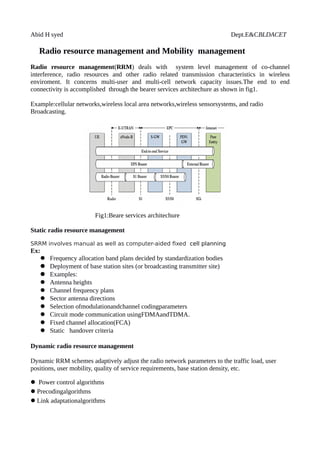
  • 1. Abid H syed Dept.E&CBLDACET Radio resource management and Mobility management Radio resource management(RRM) deals with system level management of co-channel interference, radio resources and other radio related transmission characteristics in wireless enviroment. It concerns multi-user and multi-cell network capacity issues.The end to end connectivity is accomplished through the bearer services architechure as shown in fig1. Example:cellular networks,wireless local area networks,wireless sensorsystems, and radio Broadcasting. Fig1:Beare services architechure Static radio resource management SRRM involves manual as well as computer-aided fixed cell planning Ex:  Frequency allocation band plans decided by standardization bodies  Deployment of base station sites (or broadcasting transmitter site)  Examples:  Antenna heights  Channel frequency plans  Sector antenna directions  Selection ofmodulationandchannel codingparameters  Circuit mode communication usingFDMAandTDMA.  Fixed channel allocation(FCA)  Static handover criteria Dynamic radio resource management Dynamic RRM schemes adaptively adjust the radio network parameters to the traffic load, user positions, user mobility, quality of service requirements, base station density, etc.  Power control algorithms Precodingalgorithms Link adaptationalgorithms
  • 2. Abid H syed Dept.E&CBLDACET Dynamic Channel Allocation(DCA) orDynamic Frequency Selection(DFS) algorithms, allowing "cell breathing" Traffic adaptivehandovercriteria, allowing "cell breathing" Re-use partitioning  Adaptive filtering  Single Atenna interference cancellation(SAIC) Dynamicdiversity schemes, for example Soft handover Dynamic single-frequency networks(DSFN)  Phased array antenna with beamforing Multiple-input multiple-output communications(MIMO) Space-time coding Admission control PDCP Packet Data Convergence Protocol(PDCP), is specified by 3GPP for LTE 5G New Radio (NR). The PDCP is located in the Radio Protocol Stack in the UMTS/LTE/5G, air interface on top of the RLC layer as shown in figure2 . PDCP provides its services to the RRC and user plane upper layers. e.g. IP at the UE or relay at the base station. Following services are provided by PDCP to upper layers: Transfer of user plane data Transfer of control plane data Header compression Ciphering Integrity protection The header compression technique is based on either IP header compression (RFC 2507) or Robust Header Compression(RFC 3095). If PDCP is configured for No Compression, it will send the IP Packets without compression; otherwise it will compress the packets according to its configuration by upper layer and attach a PDCP header and send the packet.
  • 3. Abid H syed Dept.E&CBLDACET Overview Figure2:PDCP, located in the Radio Protocol Stack on top of the RLC layer Radio link control (RLC) RLC is a layer 2 Radio link control used in UMTS and LTE on the air interface. It’s is specified by 3GPP for UMTS/LTE and for TS (in 5G)New Radio (NR). RLC is located on top of the 3GPP MAC-layer and below the PDCP-layer. The main function of the RLC protocol are: Transfer of upper layer Protocol Data Units (PDUs) in one of three modes: Acknowledged Mode (AM), Unacknowledged Mode (UM) and Transparent Mode (TM) Error correction through ARQ(only for AM data transfer) Concatenation, segmentation and reassembly of RLC SDUs (UM and AM) Re-segmentation of RLC data PDUs (AM) Reordering of RLC data PDUs (UM and AM); Duplicate detection (UM and AM); RLC SDU discard (UM and AM) RLC re-establishment Protocol error detection and recovery
  • 4. Abid H syed Dept.E&CBLDACET PDU headers and formats A protocol data unit(PDU) is a single unit of information transmitted among peer entities of acomputer network. A PDU is composed of protocol-specific control information and user data as shown in fig3 Fig3:Formats of RLC Data PDU The RLC have the fallowing fields: Framing Info(FI) field:Indiactes wether RLC SDU is segmented at the begining and/or end of data field Length field(LI): Indiactes length in bytes of corresponding data. Extension bit field(E): Whether a data field follows or a set of E-field. SN field:It indiactes the sequence no of corresponding UMD or AMD PDU RLC Modes: RLC has got the fallowing modes. Transparent Mode • No segmentation and reassembly of RLC SDUs • No RLC headers are added • No delivery guarantees • Suitable for carrying voice Unacknowledged Mode • Segmentation and reassembly of RLC SDUs • RLC Headers are added • No delivery guarantees • Suitable for carrying streaming traffic Acknowledged Mode • Segmentation and reassembly of RLC SDUs • RLC Headers are added • Reliable in sequence delivery service • Suitable for carrying TCP traffic
  • 5. Abid H syed Dept.E&CBLDACET LTE MAC PDU is a bit string but octet aligned (i.e multiple of 8 bits). A MAC PDU header consists of one or more subheaders. Each subheader corresponds to either a MAC SDU, MAC control element or padding.MAC PDU header can have these six elements R/R/E/LCID/F/L. The last subheader in MAC PDU and subheaders for MAC control elements consists solely of four elements R/R/E/LCID. A MAC PDU subheader corresponding to padding consists of the four header fields R/R/E/LCID.Here are some of the guidelines followed when multiple subheaders need to be present in a single MAC PDU MAC PDU subheaders have the same order as MAC SDUs, MAC control elements and padding MAC control elements always placed before MAC SDU. Padding occurs at the end of MAC PDU except when single byte or two bytes padding required. When single-byte or two-byte padding is required, one or two MAC PDU subheaders corresponding to padding are placed at the beginning of the MAC PDU before any other MAC PDU subheader. A maximum of one MAC PDU can be transmitted per TB per UE. A maximum of one MCH MAC PDU can be transmitted per TTI as shown in fig4. Figure4:MAC PDU Radio Resource Control(RRC) RRC protocol is used in UMTS and LTE on the air interface. It is a layer that exists between UE and eNB and exists at the IP level (Layer 3/Network Layer). This protocol is specified by3GPPi in TS 36.331 for LTE. RRC messages are transported via thePDCP-Protocol. Functions of the RRC  Connection establishment and release functions  Broadcast of system information
  • 6. Abid H syed Dept.E&CBLDACET  Radio bearer establishment, reconfiguration and release  RRC connection mobility procedures  Paging notification and release and outer loop power control Fig5:PDCP data PDU format for user plane and control plane RRC overview RRC has got only two states :i.RRC_idle ii.RRC_connected as shown in fig6.A UE is in the RRC CONNECTED state when an “RRC_connected” connection, has been established otherwise it’s in the IDLEstate. Fig6:RRC states Functions IDLEstate: RRC CONNECTED UE controlled mobility Unicast data transfer Paging Broadcast of system information Network controlled mobility Paging Broadcast of system information
  • 7. Abid H syed Dept.E&CBLDACET Mobility Management Entity Mobility Management Entity (MME) is responsible for the mobility management function. The MME is connected to a large number of evolved Node Bs (cells) as shown in fig7. They are grouped into the Tracking Areas (TAs). The TAs are further grouped into TA Lists (TALs). When a User Equipment (UE) moves out of the current TAL, it reports its new location to the MME. If the LTE network attempts to connect to the UE, the MME asks the cells in the TAL to page the UE. In LTE paging, the MME may se-quentially page a cell, the TA of the cell, and/or TAL of the cell. The performance of paging and the guidelines for the best paging sequence of cells. Fig7:MME connected to e_NodeBs S1 mobility: S1 mobility is semilar to UMTS serving radio network subsystem(SRNS).It consists of fallowing steps,as shown in fig8. Fig8:S1 interface signal flow
  • 8. Abid H syed Dept.E&CBLDACET 1. Preparation Phase : A target MME and eNode-B is identified when decision for a handover is taken. The network has to allocate resources to target side for the impending handover . The MME sends a handover request to the target eNode-B requesting it to set up the appropriate resources for the UE . Once resources have been allocated at the target eNode-B , it sends a handover request ACK to the MME . Once this message is received by the MME , it sends a handover command to the UE via the source eNode-B . 2 . Execution Phase :After receiving the handover command, the UE responds by performing the various RAN related procedures needed for the handover including accessing the target eNode-B, using the Random Access Channel (RACH) .While the UE performes the handover , the source eNode-B initiates the status transfer where the PDCP context of the UE is transfered to the target eNode-B . The source eNode-B also forwards the data stored in PDCP buffer to the target eNode-B . Once the status and the data have been transfered to the target eNode-B and the UE is able to establish a Radio Access Bearer (RAB) on the target eNode-B , it sends the handover confirm message to the target eNode-B. 3 . Completion Phase : When the target eNode-B receives the handover confirm message , it sends a handover notify message to the MME. The MME then informs the source eNode-B to release the resources originally used by the UE. X2 mobility: It’s the default mode of operation, unless X2 mode is not avialable between source and target eNode-Bs. Fig9:X2 interface signal flow
  • 9. Abid H syed Dept.E&CBLDACET It has got the fallowing phases. 1.Preparation phase: Handover decision is made by the source eNode-B , it sends a handover request message to the target eNode-B.On recieving this message,the target eNode-B works with the MME and S-GW to set up the resources for the UE . In the case of mobility over X2 Interface , it is possible to set up resources on a per-RAB(radio access bearer) basis, which implies that upon the completion of the handover, the UE will have the same RABs at the target eNode-B with the same set of QoS as it had on the source eNode-B . This process makes the handover quick and seamless and the UE is not required to set up the RAB with the target eNode-B once the handover is completed . The target eNode-B responds to the source eNode-B with a handover request ACK once it is ready . 2 . Execution Phase : Upon receiving the handover request ACK , the source eNode-B sends a handover command to the UE . While the UE completes the various RAN-related Handover procedures , the source eNode-B starts the status and data transfer to the target eNode-B . This is done on a per-RAB basis for the UE . 3 . Completion Phase : Once the UE completes the handover procedure , it sends a handoff complete message to the target eNode-B . Then the target eNode-B sends a path switch request to the MME / S-GW and the S-GW switches the GTP tunnel to the source eNode- B to the target eNode-B .When the data path in the user plane is switched , the target eNode-B sends a message to the source eNode-B to release the resources originally used by the UE. Inter-Cell Interference Coordination Downlink Inter-cell interference management is one of the most performance limiting factor.Inter-Cell Interference Coordination(ICIC) techniques, present a solution by applying restrictions to the RRM block, improving favorable channel conditions across subsets of users that are severely impacted by the interference, and thus attaining high spectral efficiency. The basic approaches for downlink ICI mitigation are as follows : ICI randomization In interference randomization, the user’s data are spread over a distributed set of subcarriers so that interference scenario can be randomized and frequency diversity gain can be achieved. In each cell the user’s data are sequentially allocated over a time-frequency chunks. When all the requested transmission are allocated, subcarriers permutation is made in random manner so that each UE’s transmission is arbitrarily spread up over the total time-frequency grid. Fig.10 shows the allocation
  • 10. Abid H syed Dept.E&CBLDACET of subcarriers in a given cell before and after the pseudorandom permutation. In each interfering cell, the pseudorandom permutation is performed independently. The cell specific scrambling causes the interference spread up along with the transmission of a given user. As the coding is performed at the transmitter during transmission, the whole bit stream can be easily recovered at the receiving end. As interference system requires no signalling overhead for coordination among cells and less complex resource management, it is suitable for practical system. Fig10: Subcarrier allocation before (a) and after (b) random permutation ICI cancellation If UE is capable of decoding the interfering signals then UE can cancel it,using a multi user detector. ICI coordination / avoidance : This is achieved by restrictions to the downlink resource management in a coordinated way between neighbouring cells .The restrictions can be on time / frequency resources or transmit power used at each eNode-B . It requires additional inter-eNode-B communication and UE measurements and reporting . Static ICI coordination / avoidance : This is mainly done during the cell planning process and does not require frequent reconfiguration . Ex: static Fractional Frequency Reuse (SFFR) . Static coordination strategy requires no or little inter eNode-B signaling, but there is performance limitation as dynamic characteristics such as cell loading or user distributions are not taken into consideration . Semi- Static ICI coordination/avoidance : Semi-static coordination typically requires configurations on a time-scale of the order of seconds or longer , and inter-eNode-B communication over X2 interface is needed . The information exchanged between neighbouring eNode-Bs can be transmission power and / or traffic load on different resource blocks . By considering such information at neighbouring eNode-Bs , ICI suppression is more efficient .
  • 11. Abid H syed Dept.E&CBLDACET Uplink The basic approaches for uplink ICI mitigation are as follows : ICI randomization : Similar to the downlink , ICI randomization in the uplink is achieved by scrambling the encoded symbols prior modulation . Instead of cell-specific scrambling as used in the downlink , UE-specific scrambling is used in the uplink as ICI comes from multiple UE’s in neighbouring cells . ICI cancellation : ICI cancellation is more applicable in the uplink than in the downlink , as the eNode-B has higher computation capability and usually more antenna elements. Uplink power control : Power control is an efficient way to suppress ICI in the uplink. Fractional Power Control (FPC) is used in LTE. ICI coordination / avoidance : Similar coordination techniques discussed for downlink can be applied in the uplink , such as FFR.