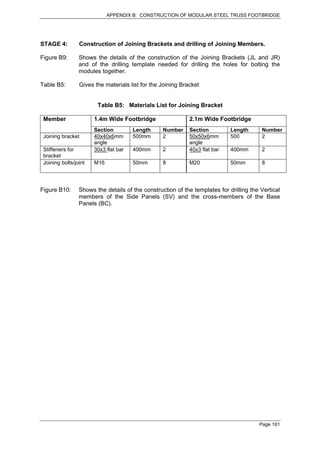
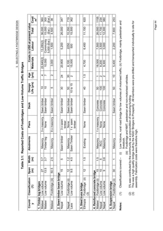
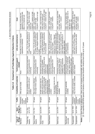
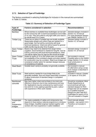
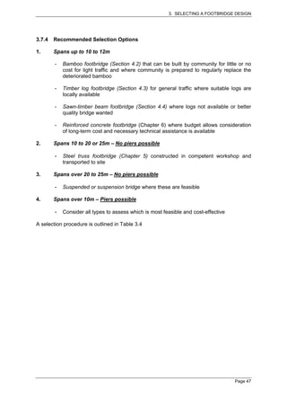
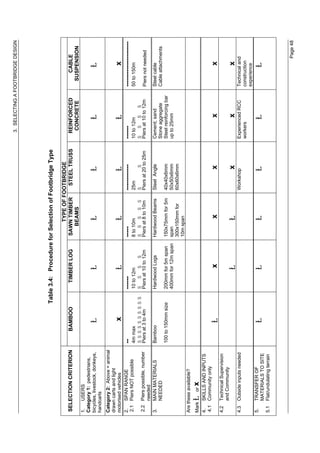
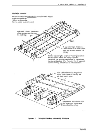
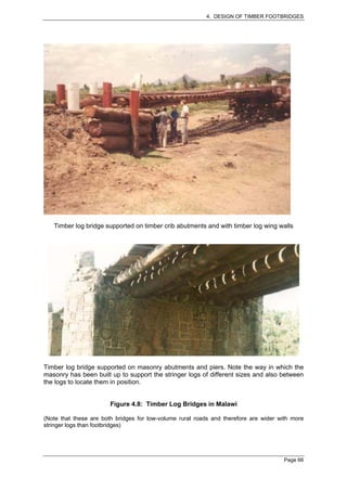
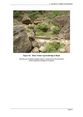
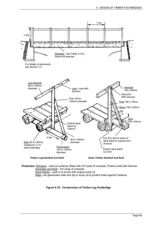
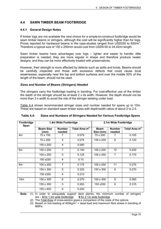
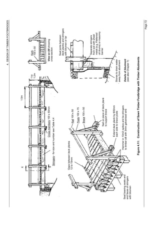
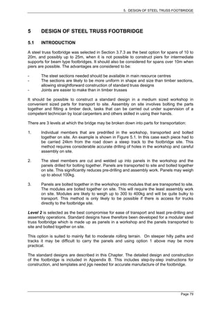
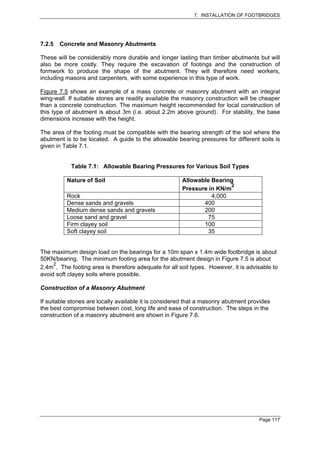
This document provides guidance on constructing footbridges at the community and district level. It discusses footbridge specifications, types of footbridges, and design considerations. The main types covered are bamboo, timber log, sawn timber, steel, reinforced concrete, and suspension bridges. Selection criteria include span, cost, materials, and maintenance requirements. Timber designs are then covered in more detail, with examples of basic, improved, and longer span bamboo footbridges. Regular maintenance is emphasized for all bridge types.

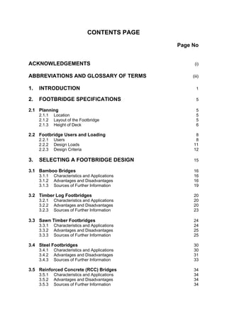


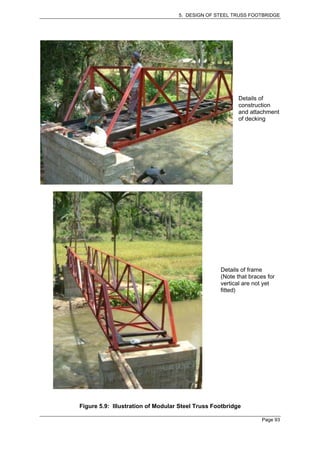
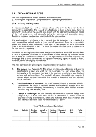
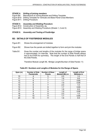
![APPENDIX B: CONSTRUCTION OF MODULAR STEEL TRUSS FOOTBRIDGE
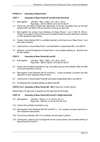
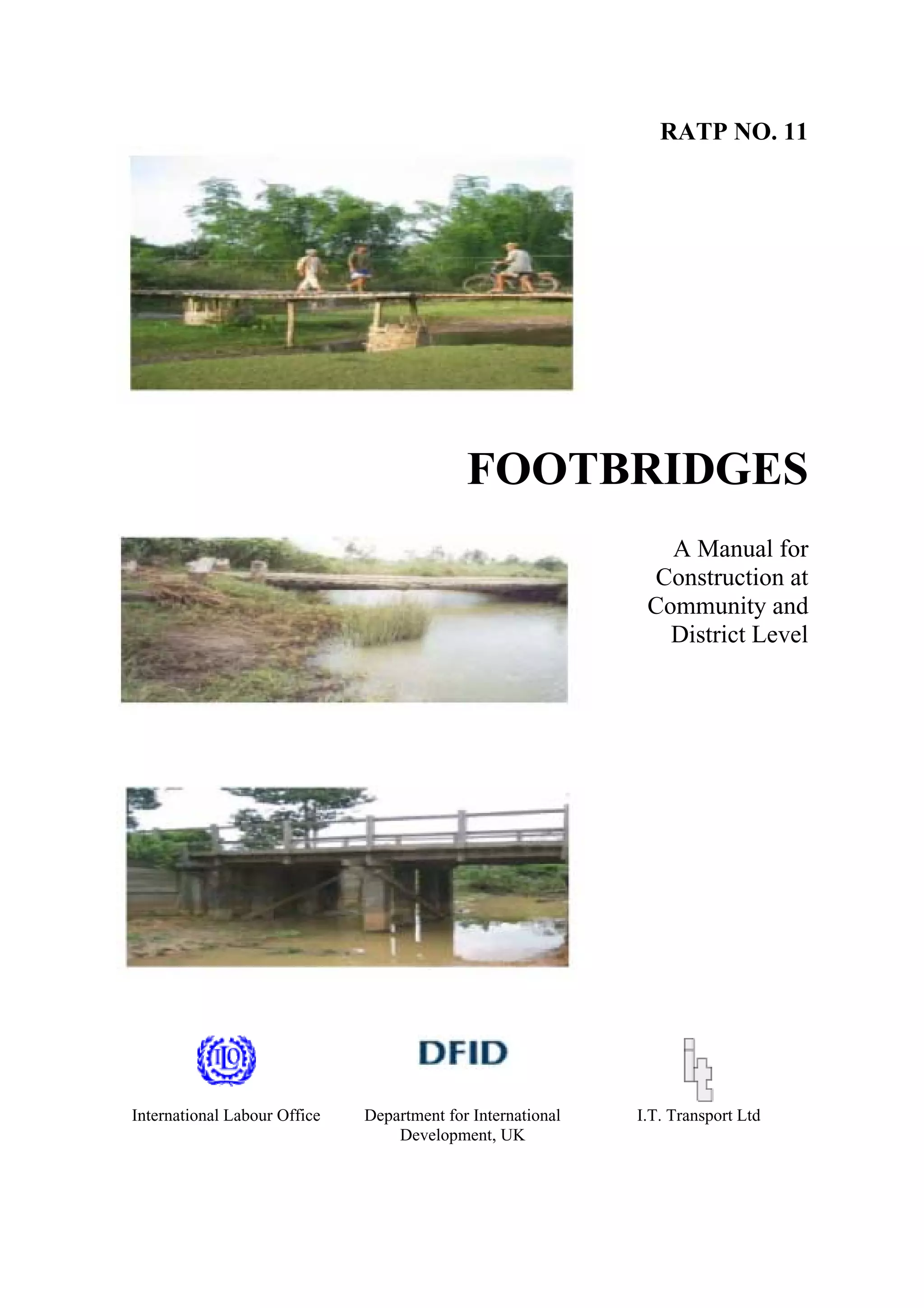
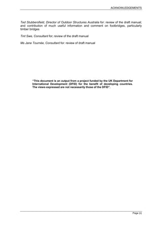
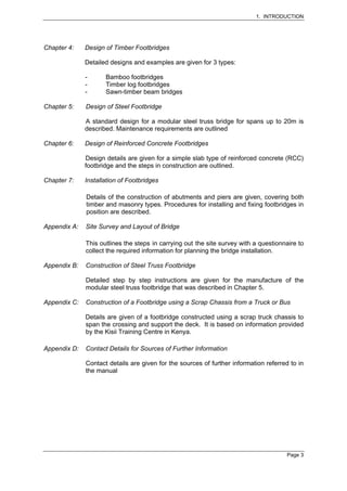
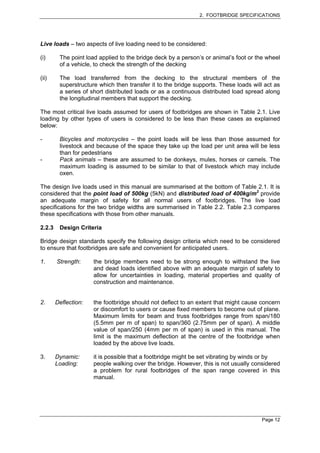
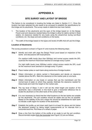
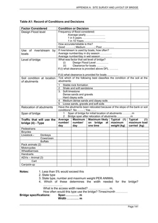
1. Bottom Longitudinal (SB)
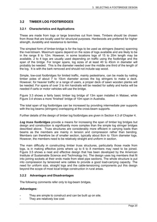
(Note: half as shown (A) and half with Gussets SG2 and SG3 reversed (b))
1.1 Cut 2 pcs angle (see Table B2) x ML long and stitch weld together to form channel section
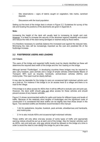
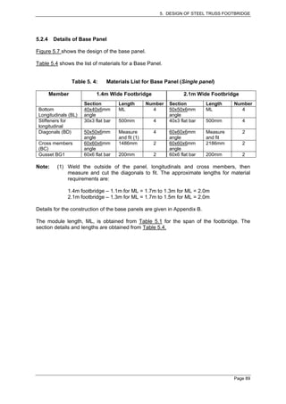
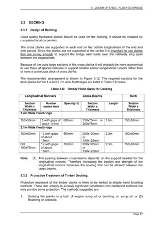
Note: The Base Panel Longitudinals and Joining
Brackets have to fit inside this space.
Therefore check fit before welding. Leave
1 or 2m gap and weld into gap
80 80 11 welds of at least 80mm
Make sure welds
long at equal spaces
are through full spacing
thickness
ML [ ]
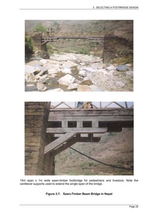
1.2 Weld on Gussets from 60 x 6mm flat bar
SG1 SG4
[ ] [ ]
6mm from
Leave 6mm space from edge for Leave small gap to weld into edge
weld and weld all round and grind weld flat
1.3 Make up second channel as in 1.1 (this has no gussets attached)
1.4 Clamp second channel accurately in position to gussets of first and weld at gussets
Weld at top, bottom and end
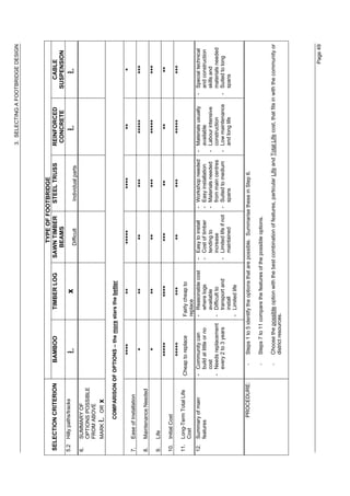
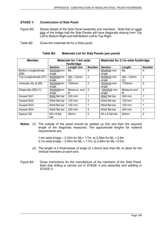
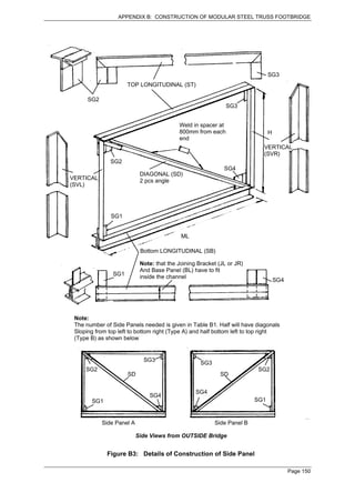
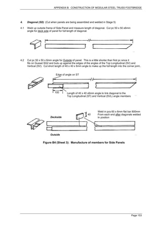
Figure B4 (Sheet 1): Manufacture of Members for Side Panels
Page 151](https://image.slidesharecdn.com/samllbridgedesign-120623034421-phpapp02/85/Samll-bridge-design-163-320.jpg)
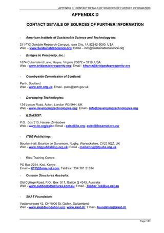
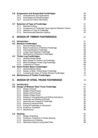
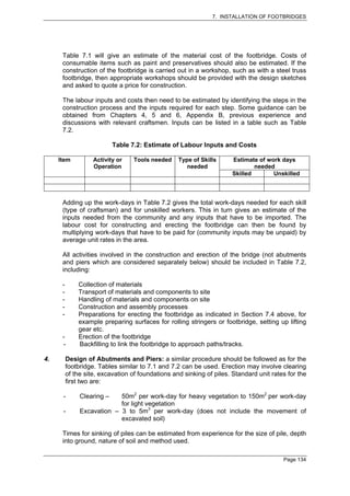
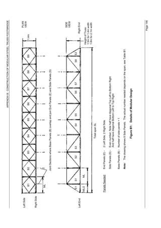
![APPENDIX B: CONSTRUCTION OF MODULAR STEEL TRUSS FOOTBRIDGE
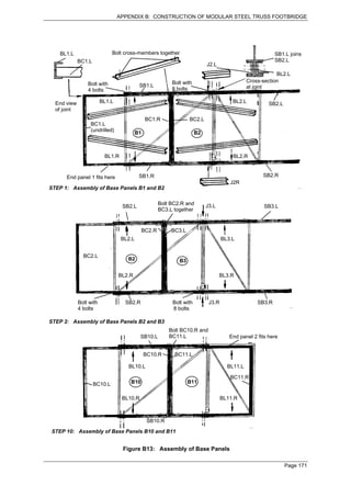
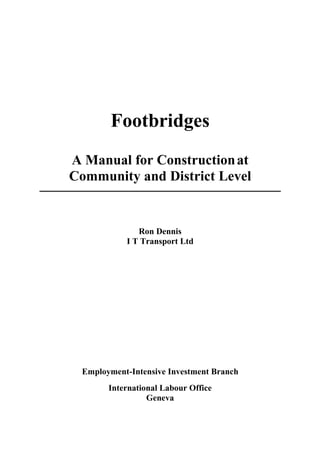
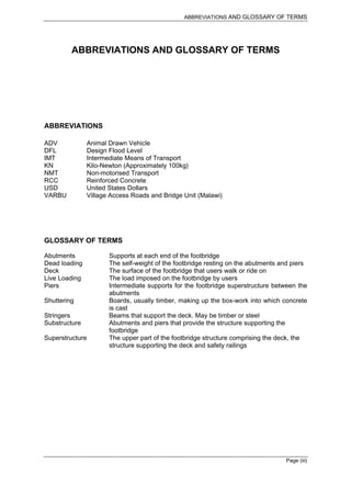
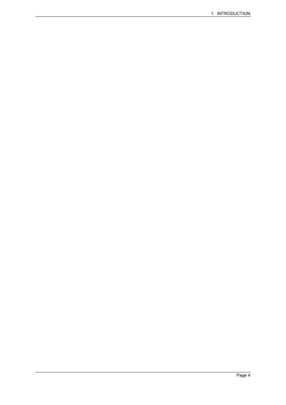
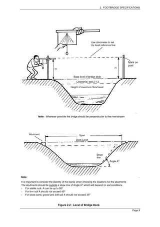
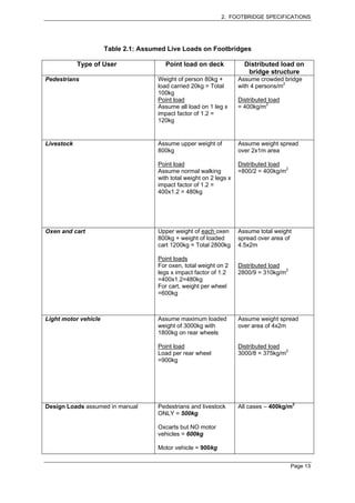
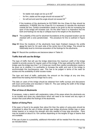
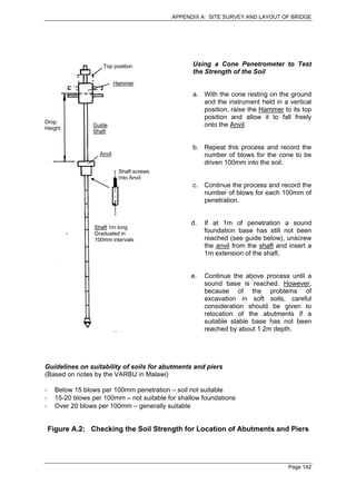
2. Top Longitudinal (ST)
2.1 Cut length of 60 x 60 x 6 angle of length (ML-12)mm
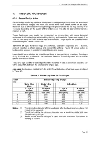
Weld on gussets cut from 60 x 6mm flat bar
(ML-12)mm [ ]
120 120
SG2 SG3
2.2 Cut second pc 60 x 60 x 6mm angle with 45o angles at each end for mitre joints with verticals.
(ML-12)mm [ ]
2.3 Weld angle sections together along top and bottom joints.
Stitch weld with 5 welds of 80mm minimum
length evenly spaced
SG2 SG3
3. Vertical members (SVL and SVR)
3.1 Cut 2 pcs 50 x 50 x 6mm angle to length H (see Table B2). Cut top end at 45o angle for
Mitre joints with Top Longitudinal
45o Angle
H H
Left hand Vertical (SVL) Right hand Vertical (SVR)
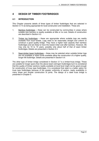
Figure B4 (Sheet 2): Manufacture of Members for Side Panels
Page 152](https://image.slidesharecdn.com/samllbridgedesign-120623034421-phpapp02/85/Samll-bridge-design-164-320.jpg)
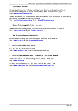
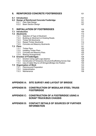
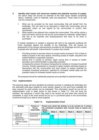
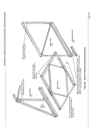
![APPENDIX B: CONSTRUCTION OF MODULAR STEEL TRUSS FOOTBRIDGE
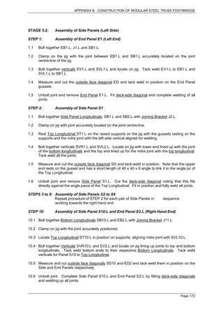
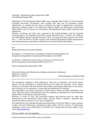
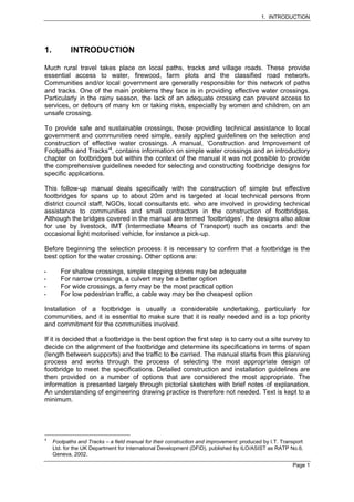
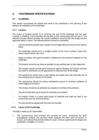
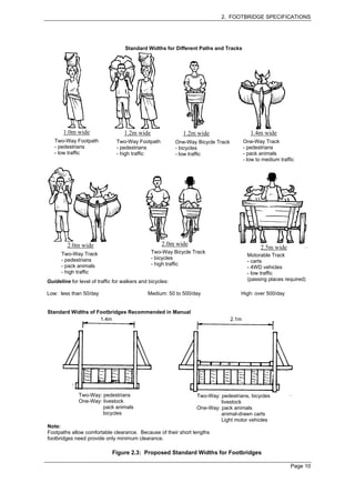
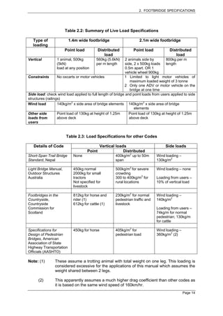
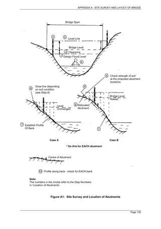
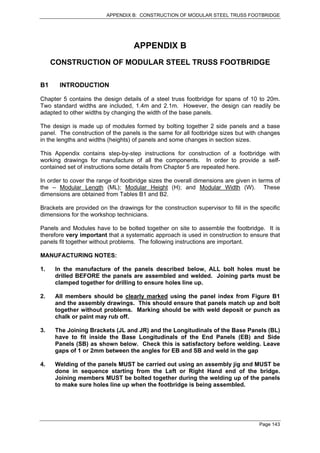
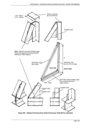
End Panel Members
1. Base longitudinal (EB) - 2 pcs channel made from angle sections (see Table B3)
1.1 Cut 2 pcs angle x ML/2 (see Table B1) long and stitch weld to form channel. 8 welds at least
60mm long at equal spacing. Leave gap of 1 to 2mm between angle pieces to weld into
spacing
60
ML/2 [ ]
1.2 Cut Gussets from 60 x 6 flat bar and trim to match angle of diagonal
EG2 Gusset EG4
EG1
[ ]
[ ] Locate 6mm from edge of channel to provide space for weld 6mm from edge
For weld
1.3 Make up second length of channel section as in 1.1 (this has NO gussets). Position
accurately and weld to gusset plates
Weld top, edge and bottom
2. Diagonal (ED) - 2 pcs angle (see Table B3). Measure and cut to length during assembly (Stage 5)
Cut at 45o angle
Measure and cut diagonals to fit
neatly in position during assembly
in Stage 5
Cut at angle to
suit joint with EB
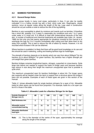
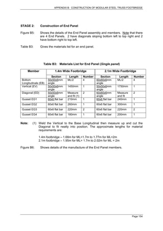
Figure B6 (Sheet 1): Members for End Panel
Page 156](https://image.slidesharecdn.com/samllbridgedesign-120623034421-phpapp02/85/Samll-bridge-design-168-320.jpg)
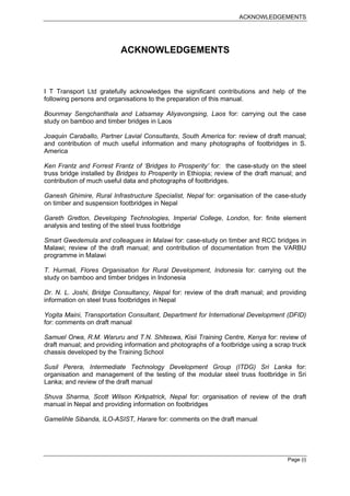
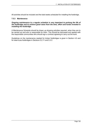
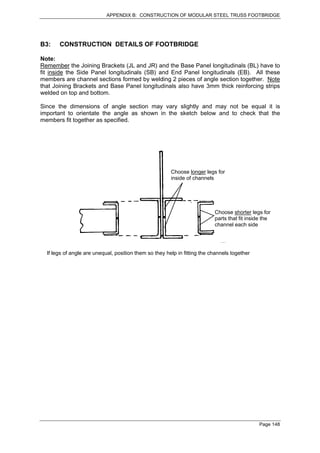
![APPENDIX B: CONSTRUCTION OF MODULAR STEEL TRUSS FOOTBRIDGE
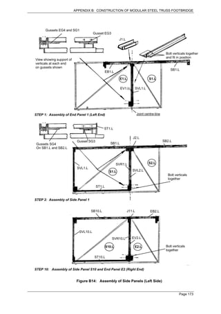
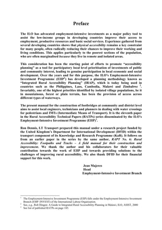
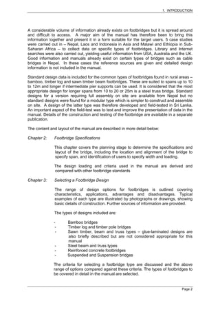
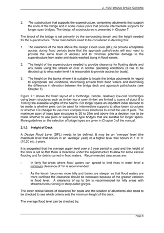
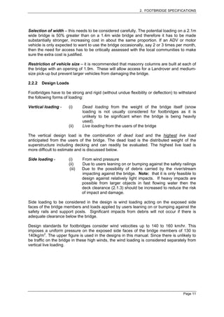
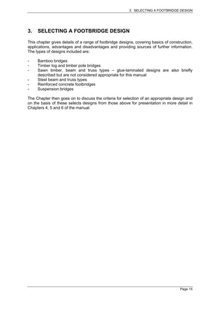
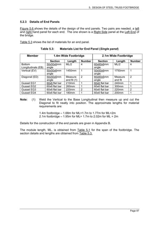
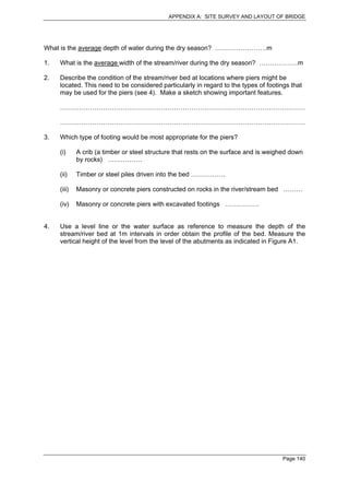
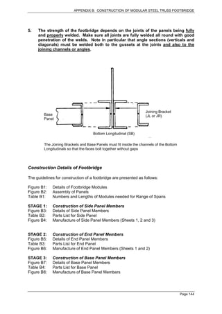
3. Vertical (EV) - 1 pc 50 x 50 x 6mm angle
3.1 Cut pc of angle of length H (see Table B3)
3.2 Cut 2 pcs of 60 x 6 flat for Gusset EG3 and weld in position
60
6mm from edge for weld
Trim to match
angle of diagonal
GUSSET EG3
220
Grind weld flat H [ ]
both sides
Cut and weld 2 pcs 60 x 6 flat bar x 220mm long
for gusset
Note: A LH and RH Vertical are needed for each End Panel as shown below
Left Side
Right Side
VIEW ON TOP OF VERTICALS
Figure B6 (Sheet 2): Members for End Panel
Page 157](https://image.slidesharecdn.com/samllbridgedesign-120623034421-phpapp02/85/Samll-bridge-design-169-320.jpg)
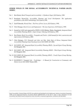
![APPENDIX B: CONSTRUCTION OF MODULAR STEEL TRUSS FOOTBRIDGE
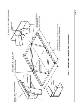
Weld all round
STIFFENERS, 30 x 3 flat bar x 500 joints
GUSSET - 60 x 60mm flat bar Long welded on top and bottom
X 200mm long of channel members
CROSS MEMBERS
60 x 60 x 6 angle
DIAGONALS
4pcs angle
ML [ ]
W
[ ]
LONGITUDINAL (each side) channel made
up by welding together 2 pcs angle section
Figure B7: Details of Base Frame
Page 159](https://image.slidesharecdn.com/samllbridgedesign-120623034421-phpapp02/85/Samll-bridge-design-171-320.jpg)
![APPENDIX B: CONSTRUCTION OF MODULAR STEEL TRUSS FOOTBRIDGE
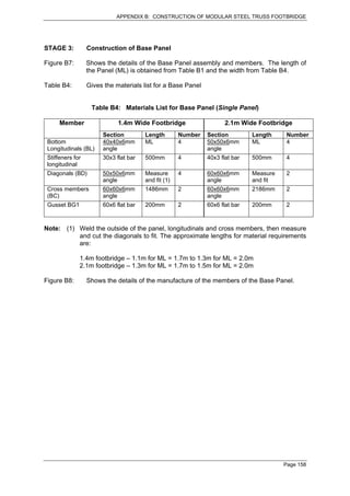
Base Frame Members
1. Longitudinals (BL)
1.1 Cut 2 lengths angle (see Table B4) and stitch weld together to form channel section. 2 pcs needed
ML [ ] (see Table B1)
Stitch weld - 11 welds at least 60mm long at equal spacing
1.2 Weld on stiffeners, 30 x 3 flat bar x 500 long, top and bottom at centre of longitudinal.
Stitch weld joints, 5 x 60mm long
Welds with spaces of 50mm
200mm
500mm
Weld on gusset, 60 x 6mm flat bar x 200mm long, at centre of bottom flange of channel
2. Cross-Members (BC)
[ ] (see Table B4)
2 pcs 60 x 60 x 6 angle
3. Diagonals (BD)
Measure and cut to fit during assembly (Stage 5)
4 pcs angle (see Table B4)
Figure B8: Members for Base Panel
Page 160](https://image.slidesharecdn.com/samllbridgedesign-120623034421-phpapp02/85/Samll-bridge-design-172-320.jpg)