Download to read offline
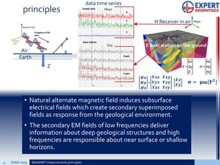
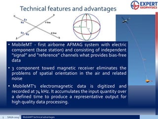
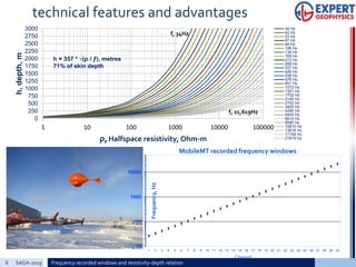
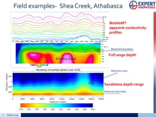
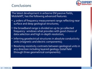

The document discusses the advancements in airborne frequency domain electromagnetic (afmag) systems, specifically focusing on the mobilemt technology that enhances data collection in conductive environments. It highlights the principles and technical features of mobilemt, including its capability to provide bias-free data and improved resolution for geological investigation. Field examples demonstrate the successful application of mobilemt in various geological contexts, showcasing its potential for better understanding subsurface structures.


![Getting Started with Apache Spark: Big Data Made Simple [Free Meetup]](https://cdn.slidesharecdn.com/ss_thumbnails/apachesparkgettingstarted-260203175547-8361bcc3-thumbnail.jpg?width=640&height=640&fit=bounds)


