Download as PDF, PPTX


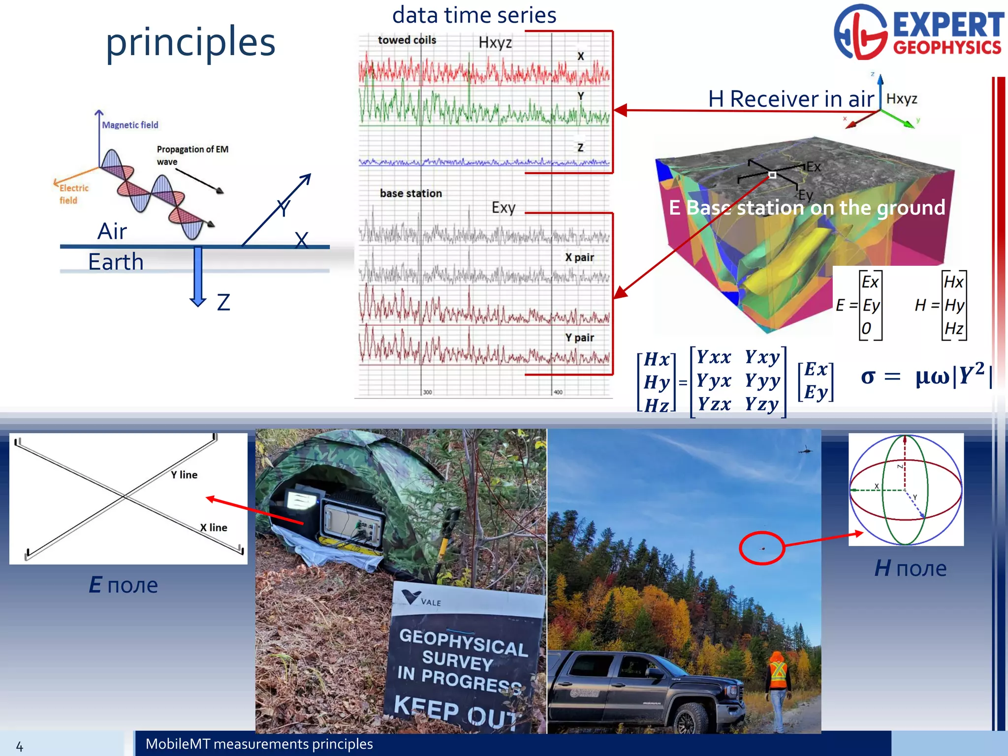

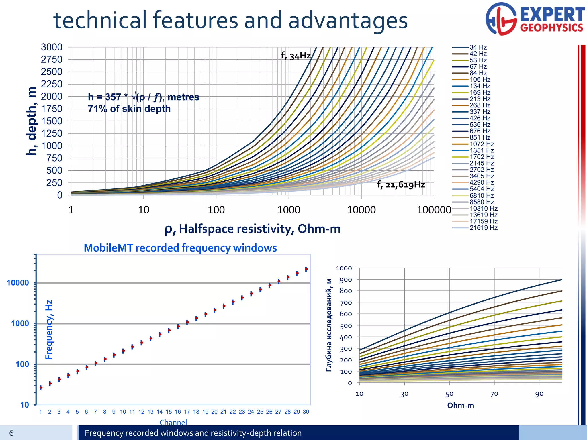


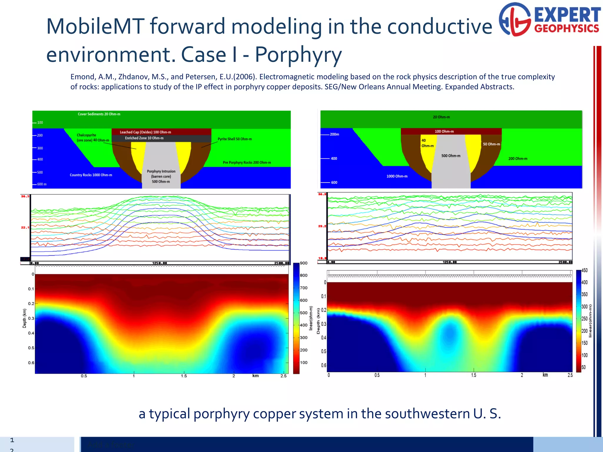

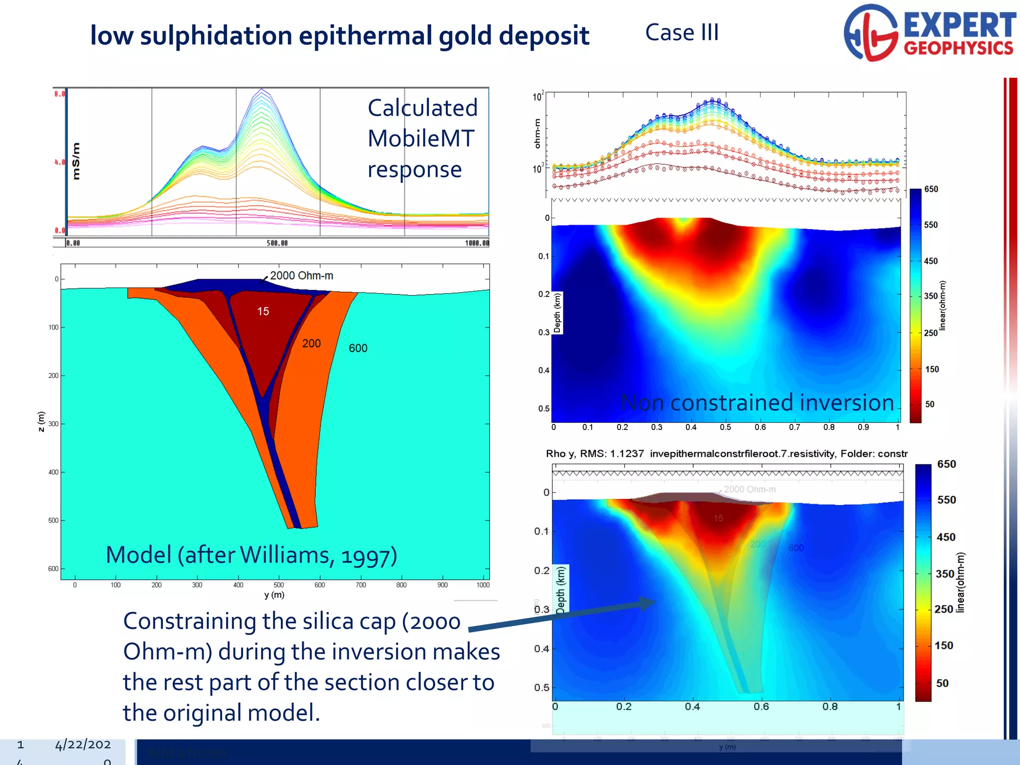
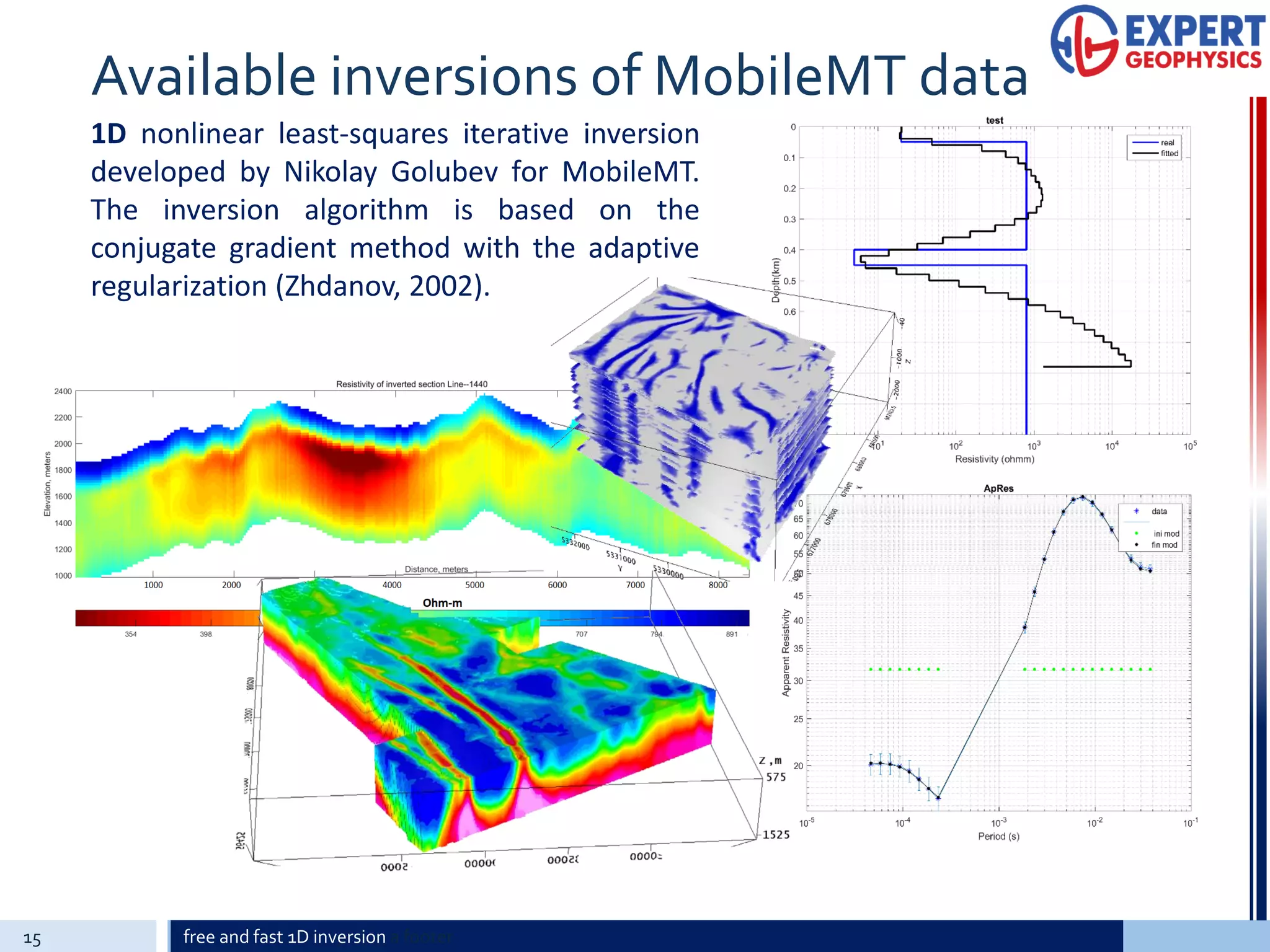


The document outlines the motivation, principles, technical features, field examples, and modeling capabilities of MobileMT, a next generation airborne audio-frequency magnetotelluric (AFMAG) system. MobileMT collects broadband electromagnetic data from 34 Hz to 21,619 Hz using independent magnetic and electric channels, allowing for high-resolution 3D inversion of resistivity structures. Field examples from Canada and Australia demonstrate MobileMT's ability to map geological units like alteration zones and basement boundaries to depths over 2.5 km in resistive environments. 1D, 2D, and 3D inversions of MobileMT data provide detailed images of subsurface resistivity contrasts useful for mineral exploration targeting.