This document discusses spray modeling for lean NOx trap aftertreatment system design. It presents Eaton Corporation's aftertreatment system for reducing NOx and PM emissions. Computational fluid dynamics (CFD) was used to optimize fuel preparation and distribution through injection modeling. Both test-based and CFD-based injection modeling were performed and validated. CFD results showed that smaller droplet sizes and optimized mixer placement improved fuel uniformity and vaporization. CFD modeling aided in comparing injector performances and selecting mixers for the aftertreatment system design.

![3
3SAE INDIA International Mobility Engineering Congress & Exposition, 2009, Chennai
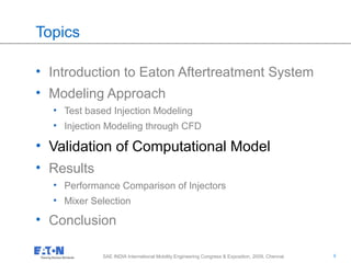
Introduction
Eaton Aftertreatment system
NOx < 0.27 gm/kW-h
PM < 0.02 gm/kW-h
Working
• Lean NOX Trap (LNT) stores the NOX
• During LNT regeneration, Reformer produces H2
and CO, which are used to purge the LNT
• LNT releases the NOX as Nitrogen and NH3
• Selective Catalytic Reduction (SCR) uses the
released NH3 and treats the slipped NOX
• Diesel Particulate Filter (DPF) traps the Particulate
Matter (PM)
Product Differentiator
• Single fluid system [Dosing System needed]
• Independent of urea infrastructure
• Flexible, customized and smaller packaging
• Scalable with engine power (size)
# Ref: Hu, DEER Conf 2006, McCarthy, SAE2009-01-2835
Emission Regulation for Highway Vehicle#
Eaton Aftertreatment System#](https://image.slidesharecdn.com/efe69fc2-8b46-46ab-a4a9-9ec7e54f8c04-160106194401/85/SAE_CONF_v1-7-3-320.jpg)
![5
5SAE INDIA International Mobility Engineering Congress & Exposition, 2009, Chennai
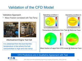
EAS modeling Approach…
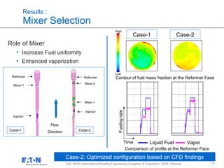
Role of CFD
• Optimize fuel preparation path
• 100% fuel vaporization
• Uniform flow and fuel distribution
Challenges
• Fuel injection modeling
Computational Domain
Exh Flow In
InjectorMixer-1Mixer-2Reformer
Boundary Condition
• Inlet – Transient Profile
• Reformer - Porous media
• Mixers: Zero Thickness wall
• Walls: Convective in steady
environment
Fuel Droplet Tracking
• Lagrangian method [DPM]
Exh Flow Out
Inlet: Transient Profile Boundary Condition
0
5
10
15
20
25
30
0 5 10 15 20 25 30
Time [sec]
ExhMassFlux[kg/m^2-s]
0
100
200
300
400
500
600
Fueling[gpm];Temperature[K]
B25 Exhaust Mass Flux (kg/m^2-2) B25 Exhaust Temperature (K)
B25 Exhaust O2 Concentration (%) B25 Fuel Mass Flow (grams/min)
0
2
4
6
8
10
O2Concentration[%]](https://image.slidesharecdn.com/efe69fc2-8b46-46ab-a4a9-9ec7e54f8c04-160106194401/85/SAE_CONF_v1-7-5-320.jpg)
![7
7SAE INDIA International Mobility Engineering Congress & Exposition, 2009, Chennai
Axis
Spool wall
Wall
SwirlChamber Point of
Injection
Axis
Direction Vector
• Axial
• Swirl
Axis
Spool wall
Wall
SwirlChamber Point of
Injection
Axis
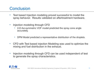
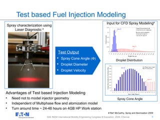
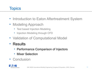
Injection Modeling through CFD
Step -1 : Geometry Details
Multiphase Flow Simulation
(Volume of Fluids -- VOF)
Step-2: Droplet Modeling [DPM]
Pressure Swirl Atomizer (Break up
& Coalescence)
• Droplet Distribution
• Droplet Diameter
• Spray Cone Angle
• Pressure Drop
2- D Axisymmetric VOF Domain 2- D Axisymmetric DPM Domain
Injector Geometry
Step-1 - VOF Step-2
Computational Domain
for Droplet Modeling](https://image.slidesharecdn.com/efe69fc2-8b46-46ab-a4a9-9ec7e54f8c04-160106194401/85/SAE_CONF_v1-7-7-320.jpg)
![12
12SAE INDIA International Mobility Engineering Congress & Exposition, 2009, Chennai
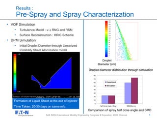
Results :
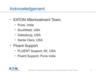
Performance Comparison of Injectors
Comparison of wall wetting and Mass Fraction contour
Exhaust System with Spray A
Exhaust System with Spray B
Smaller droplets : Higher fuel uniformity and Better vaporization
• Spray A [ Large Droplets ]
• Fuel uniformity is low
• Higher wall wetting
• Spray B [ Small Droplets]
• Higher fuel uniformity
• Low wall wetting
Diameter distribution of droplets
Spray B
Spray A
High
Low](https://image.slidesharecdn.com/efe69fc2-8b46-46ab-a4a9-9ec7e54f8c04-160106194401/85/SAE_CONF_v1-7-12-320.jpg)