This document discusses statistical methods for determining the replacement interval of pressure relief valves based on pop test data. It provides background on Weibull analysis and how it can be used to analyze small sample sizes. The document outlines how to generate a Weibull plot from test data and conduct a Weibayes analysis when there are few or no failures. An example of using Weibayes to determine a new replacement interval when testing 30 valves for 5 years resulted in zero failures is presented.
Juan Pablo Hernández presented information on control valve sizing for compressible fluids. Control valves are used to meet process conditions and product quality specifications. Three methods for sizing control valves were compared: hand made calculations, Fisher software, and Aspen Hysys simulation. All three methods produced similar results for the example case of sizing a control valve for superheated steam. However, the Fisher software was identified as the preferred method due to providing reliable sizing in less time compared to hand calculations.
In November 2011, Hydrocarbon Processing published a paper that documented a method to determine if relief devices were susceptible to chatter. Other methods are being developed to determine the chances of chatter for a specific installation; however, the model discussed in the published paper is the only screening method that places the relief devices into two categories: (1) those installations that may chatter and (2) those installations that need no further review. The goal of any experimental comparison is that it will error on the side of predicting chatter, but will be reliable enough to screen valves. Since the publication of that article, the Oil & Gas industry has continued to struggle with the issue of relief device stability so much so that API delayed issuance of API STD 520 Part II Sizing, Selection, and Installation of Pressure-Relieving Devices in Refineries-Part II, Installation. This paper compares instances of known chatter to research conducted by API, and uses this comparison to evaluate the model. Thus far, based on research and all acquired information, the method predicted all instances of chatter known to the authors.
Ritepro Corporation produces Check Rite combination check valves that employ both spring and gravity forces to close. They provide reliability, rapid closing, and low pressure loss. Check Rite valves are easier to install horizontally or vertically compared to conventional check valves due to their compact design. They are also lighter, more compact, and open fully at lower velocities than swing or tilting check valves. This results in increased reliability and significant savings in weight, size, pressure drop, and energy costs compared to other check valve designs.
The document discusses traditional methods for sizing valves for liquid flow. It explains that improper valve sizing can be expensive and cause process issues. The traditional method involves determining the valve sizing coefficient (Cv) based on published values, accounting for factors like pressure differential, fluid properties, and viscosity. A key equation relates Cv to flow rate, with corrections for non-ideal fluids. Graphs are provided to correct for viscosity and determine the actual required Cv for a given application. Selecting a valve with a Cv equal or higher than required will ensure sufficient flow.
This document provides an overview of early sizing considerations for pressure safety valves (PSVs). It defines important terminology related to PSVs and describes the types and operating principles of conventional, balanced bellow, and pilot-operated PSVs. The document outlines the procedure for early PSV sizing, including identifying capacity requirements, applicable standards, and inter-discipline interfaces. It also notes lessons learned regarding material selection and potential failure modes of bellow-type PSVs.
This document provides an overview of early sizing considerations for pressure safety valves (PSVs). It discusses important terminologies, types of PSVs, sizing basis, applicable standards, and the early sizing procedure. The procedure involves selecting possible orifice areas to meet capacity requirements. The objectives of early sizing are to remove holds in piping and instrumentation diagrams and allow early release of piping designs. The document also discusses inter-discipline interfaces, lessons learned, and quality management system documents related to PSV sizing.
This document provides an overview of control valves, including applicable standards, types of control valves, leakage classes, characteristics, selection criteria, and noise and cavitation controls. It discusses control valve fundamentals like flow characterization using different cage designs, cavitation and flashing issues, and remedies. The document also summarizes Reliance Petroleum's control valve selection process and installed base of control valves from manufacturers like Fisher, ABB, and CCI.
Finding Bugs Faster with Assertion Based Verification (ABV)DVClub
1) Assertion-based verification introduces assertions into a design to improve observability and controllability during simulation and formal analysis.
2) Assertions define expected behavior and can detect errors by monitoring signals within a design.
3) An assertion-based verification methodology leverages assertions throughout the verification flow from module to system level using various tools like simulation, formal analysis, and acceleration for improved productivity, quality, and reduced verification time.
This document discusses process capability and measurement indices. It defines common and assignable causes of variation, and explains how to measure a process by taking samples and analyzing the resulting distribution. The key metrics for measuring process capability are Cp, which indicates if a process can produce within specifications regardless of the process mean, and Cpk, which also considers how centered the process is within specifications. Examples are provided to demonstrate how to calculate Cp and Cpk. The goal is for these metrics to be above 1 to indicate a capable process.
"Performance Monitoring for Efficiency" presents an ongoing commissioning process to ensure buildings stay energy efficient over time.
Tom Anderson's and Emily Cross' presentation at the 2012 Better Buildings by Design Conference uses the Burlington International Airport as a case study.
Air Logic Power Systems (ALPS) is a leading manufacturer of container leak testing equipment. Their equipment offers 5 main value propositions: 1) Increased speed and sensitivity for detecting smaller leaks; 2) Modern touchscreen controls for ease of use; 3) Simple setup requiring no tools or training; 4) Self-monitoring features to ensure proper functioning; and 5) Enhanced leak detection capabilities. Founded in 1974, ALPS has installed over 2,500 leak testing machines globally that test over 50 billion containers annually across industries such as beverage, food, and pharmaceuticals.
Calibration on the Cobas c111 - Gideon EtowaGideonEtowa
Calibration on the c111 instrument is not passing. The document provides information about calibration, including the purpose of calibration to generate a calibration factor to calculate sample results using a standard solution. It discusses set calibration, lot calibration, calibration sequences, handling calibrators, possible causes of calibration failure, and provides a quiz.
Statistical quality control (SQC) refers to the statistical tools used by quality professionals. SQC was pioneered in the 1920s by Walter Shewhart who developed control charts. Shewhart consulted on applying control charts during WWII. W. Edwards Deming helped introduce SQC methods to American and Japanese industry. SQC includes descriptive statistics, statistical process control (SPC), and acceptance sampling. Descriptive statistics describe quality characteristics while SPC uses control charts to monitor processes and determine if they are in a state of statistical control. Acceptance sampling involves inspecting samples to determine if full lots meet standards.
The Friedman test is a non-parametric alternative to the one-way ANOVA with repeated measures that is used to test for differences between groups when the dependent variable is ordinal. It can be used with continuous data that violates the assumptions of one-way ANOVA. The test assumes that samples are from a population and measured at the ordinal or higher level, and that the samples are not normally distributed. It involves ranking the data and calculating a test statistic M to determine if there are statistically significant differences between treatment columns. An example is provided comparing the rankings of three violins rated by 10 subjects.
JGB’s Enterprises' Large Diameter Hose (LDH) division was born from our clients demand for quick response assemblies. From standard Sewer By-pass, Well Point jobs, and de-watering services, to emergency response irrigation & flood zone application, JGB has the LDH Hose, Fittings, and Assemblies for you!
This document discusses reliability concepts including failure rates, reliability, constant failure rate assumptions, exponential distributions, availability, acceptance sampling plans, and system reliability. It provides examples of calculating reliability for components in series and parallel, as well as combination systems. Key points covered include defining reliability as the probability of no failure over a given time period, using exponential distributions to model constant failure rates, and how the configuration of components (series, parallel, combination) determines overall system reliability.
The document discusses methods for extending maintenance check intervals for aircraft to increase availability and reduce costs. It proposes using reliability data from aircraft systems to determine if check intervals can be safely increased through analytical approaches like Weibull analysis. A case study models extending a check C interval from 1600 to 2000 flight hours for a hydraulic system. Statistical tests of reliability parameters from the system's data over several years would need to support the interval extension without adversely affecting safety.
This document provides an overview of well testing equipment and procedures used by Power Well Service Groups and Halliburton to evaluate oil and gas reservoirs. It begins by expressing appreciation for the companies providing well testing presentation materials. It then covers various types of well testing equipment like drill stem testing tools and surface testing packages. The remainder of the document discusses objectives and details of drill stem testing and describes components of typical open hole and cased hole drill stem testing systems. It also covers surface well testing facilities, data acquisition systems, reporting formats, and emergency shutdown systems.
PAT for packaging real time monitoring of pharmaceutical bottles’ induction s...PT Asia Limited
- The need for PAT Packaging
- Sealing integrity inspection methods
- What is thermal imaging?
- The induction sealing process
- Case studies
- Reliability test
- Summary
- About DIR Technologies
DIR Technologies | PAT for Packaging by Fabian SchapiroDIR Technologies
The need fpr PAT in packaging:
1) The primary package is an integral part of the drug.
2) The sealing process of the package must be validated and monitored.
3) In a PAT framework, 100% inspection of the seal integrity is the ideal approach.
Previously there was no process analytical technology for continuous process verification of the sealing process. Sampling was the best option available. Now there is a technological, 100% in-line, non-destructive, testing method.
Summary:
1) Sampling provides probabilistic monitoring and cannot provide a solid process analytical control.
2) Thermal imaging technology enables a PAT approach to the induction sealing process with 100% in-line testing and process monitoring => Continued Process Verification
3) Case studies from packaging lines reflect the potential impact of PAT for induction sealing.
4) Reliability of Induction Integrity Verification System tested and proved.
*presentation given at IFPAC 2015 session
statistical quality control, the use of statistical methods in the monitoring and maintaining of the quality of products and services. One method, referred to as acceptance sampling, can be used when a decision must be made to accept or reject a group of parts or items based on the quality found in a sample.
1. The document discusses using accelerated testing to demonstrate reliability for high-reliability products with long lifetimes and no failures during testing. It proposes testing a small number of products for longer lifetimes or more cycles to simulate longer usage.
2. A life cycle simulator tool is introduced that can optimize accelerated testing programs to minimize costs and risks for suppliers and consumers. It analyzes multiple product components and failure modes.
3. The tool seeks the optimal testing plan, including sample sizes, test durations, acceleration levels, and warranty terms to improve reliability while balancing development, production, and warranty costs.
Explained Valve opening methods & few capacitiesVrushtiVarma
Here, numerous valves achieve comparable objectives they do as such precisely can change. If your valve castings contain elastomers, also be considered for their chemical compatibility as well as pressure and temperature limits.
SIS “Final Element” Diagnostics Including The SOV, Using A Digital Valve Cont...Emerson Exchange
This document discusses using a digital valve controller to improve diagnostics and testing of safety instrumented system (SIS) final control elements. Traditional testing methods are difficult and costly. A digital valve controller allows for partial stroke testing online which improves reliability while reducing costs. It also enables solenoid valve health monitoring and diagnostic capabilities. Field experience from Ras Gas in Qatar demonstrated benefits like reduced labor and improved predictive maintenance through signature-based testing and continuous monitoring.
RE-FRAC OF SHALE WELLS USING ARTIFICIAL INTELLIGENCEiQHub
This document discusses using artificial intelligence to optimize re-fracturing of shale wells. It notes that shale wells are fractured in multiple stages with multiple clusters, but not all clusters produce the same amount. Artificial intelligence can be used to identify production from each cluster and reasons for variations in order to determine which stages need re-fracturing. The document provides examples of how AI could be used to history match, calibrate, and validate production forecasts for each cluster to optimize re-fracturing and future well completions.
This document discusses the validation of dissolution test apparatus. It begins with a brief history of validation and reasons for validating equipment. Validation ensures equipment operates consistently and accurately. The document then discusses various types of dissolution test apparatus and the qualification process, including design, installation, operational, and performance qualification. It also addresses sources of error and concludes that acceptable qualification demonstrates the apparatus is validated for use in dissolution testing.
CHINA’S GEO-ECONOMIC OUTREACH IN CENTRAL ASIAN COUNTRIES AND FUTURE PROSPECTjpsjournal1
The rivalry between prominent international actors for dominance over Central Asia's hydrocarbon
reserves and the ancient silk trade route, along with China's diplomatic endeavours in the area, has been
referred to as the "New Great Game." This research centres on the power struggle, considering
geopolitical, geostrategic, and geoeconomic variables. Topics including trade, political hegemony, oil
politics, and conventional and nontraditional security are all explored and explained by the researcher.
Using Mackinder's Heartland, Spykman Rimland, and Hegemonic Stability theories, examines China's role
in Central Asia. This study adheres to the empirical epistemological method and has taken care of
objectivity. This study analyze primary and secondary research documents critically to elaborate role of
china’s geo economic outreach in central Asian countries and its future prospect. China is thriving in trade,
pipeline politics, and winning states, according to this study, thanks to important instruments like the
Shanghai Cooperation Organisation and the Belt and Road Economic Initiative. According to this study,
China is seeing significant success in commerce, pipeline politics, and gaining influence on other
governments. This success may be attributed to the effective utilisation of key tools such as the Shanghai
Cooperation Organisation and the Belt and Road Economic Initiative.
A review on techniques and modelling methodologies used for checking electrom...nooriasukmaningtyas
The proper function of the integrated circuit (IC) in an inhibiting electromagnetic environment has always been a serious concern throughout the decades of revolution in the world of electronics, from disjunct devices to today’s integrated circuit technology, where billions of transistors are combined on a single chip. The automotive industry and smart vehicles in particular, are confronting design issues such as being prone to electromagnetic interference (EMI). Electronic control devices calculate incorrect outputs because of EMI and sensors give misleading values which can prove fatal in case of automotives. In this paper, the authors have non exhaustively tried to review research work concerned with the investigation of EMI in ICs and prediction of this EMI using various modelling methodologies and measurement setups.
More Related Content
Similar to R&T 2007 - Replacement Interval Calculations - Elder.pdf
This document discusses process capability and measurement indices. It defines common and assignable causes of variation, and explains how to measure a process by taking samples and analyzing the resulting distribution. The key metrics for measuring process capability are Cp, which indicates if a process can produce within specifications regardless of the process mean, and Cpk, which also considers how centered the process is within specifications. Examples are provided to demonstrate how to calculate Cp and Cpk. The goal is for these metrics to be above 1 to indicate a capable process.
"Performance Monitoring for Efficiency" presents an ongoing commissioning process to ensure buildings stay energy efficient over time.
Tom Anderson's and Emily Cross' presentation at the 2012 Better Buildings by Design Conference uses the Burlington International Airport as a case study.
Air Logic Power Systems (ALPS) is a leading manufacturer of container leak testing equipment. Their equipment offers 5 main value propositions: 1) Increased speed and sensitivity for detecting smaller leaks; 2) Modern touchscreen controls for ease of use; 3) Simple setup requiring no tools or training; 4) Self-monitoring features to ensure proper functioning; and 5) Enhanced leak detection capabilities. Founded in 1974, ALPS has installed over 2,500 leak testing machines globally that test over 50 billion containers annually across industries such as beverage, food, and pharmaceuticals.
Calibration on the Cobas c111 - Gideon EtowaGideonEtowa
Calibration on the c111 instrument is not passing. The document provides information about calibration, including the purpose of calibration to generate a calibration factor to calculate sample results using a standard solution. It discusses set calibration, lot calibration, calibration sequences, handling calibrators, possible causes of calibration failure, and provides a quiz.
Statistical quality control (SQC) refers to the statistical tools used by quality professionals. SQC was pioneered in the 1920s by Walter Shewhart who developed control charts. Shewhart consulted on applying control charts during WWII. W. Edwards Deming helped introduce SQC methods to American and Japanese industry. SQC includes descriptive statistics, statistical process control (SPC), and acceptance sampling. Descriptive statistics describe quality characteristics while SPC uses control charts to monitor processes and determine if they are in a state of statistical control. Acceptance sampling involves inspecting samples to determine if full lots meet standards.
The Friedman test is a non-parametric alternative to the one-way ANOVA with repeated measures that is used to test for differences between groups when the dependent variable is ordinal. It can be used with continuous data that violates the assumptions of one-way ANOVA. The test assumes that samples are from a population and measured at the ordinal or higher level, and that the samples are not normally distributed. It involves ranking the data and calculating a test statistic M to determine if there are statistically significant differences between treatment columns. An example is provided comparing the rankings of three violins rated by 10 subjects.
JGB’s Enterprises' Large Diameter Hose (LDH) division was born from our clients demand for quick response assemblies. From standard Sewer By-pass, Well Point jobs, and de-watering services, to emergency response irrigation & flood zone application, JGB has the LDH Hose, Fittings, and Assemblies for you!
This document discusses reliability concepts including failure rates, reliability, constant failure rate assumptions, exponential distributions, availability, acceptance sampling plans, and system reliability. It provides examples of calculating reliability for components in series and parallel, as well as combination systems. Key points covered include defining reliability as the probability of no failure over a given time period, using exponential distributions to model constant failure rates, and how the configuration of components (series, parallel, combination) determines overall system reliability.
The document discusses methods for extending maintenance check intervals for aircraft to increase availability and reduce costs. It proposes using reliability data from aircraft systems to determine if check intervals can be safely increased through analytical approaches like Weibull analysis. A case study models extending a check C interval from 1600 to 2000 flight hours for a hydraulic system. Statistical tests of reliability parameters from the system's data over several years would need to support the interval extension without adversely affecting safety.
This document provides an overview of well testing equipment and procedures used by Power Well Service Groups and Halliburton to evaluate oil and gas reservoirs. It begins by expressing appreciation for the companies providing well testing presentation materials. It then covers various types of well testing equipment like drill stem testing tools and surface testing packages. The remainder of the document discusses objectives and details of drill stem testing and describes components of typical open hole and cased hole drill stem testing systems. It also covers surface well testing facilities, data acquisition systems, reporting formats, and emergency shutdown systems.
PAT for packaging real time monitoring of pharmaceutical bottles’ induction s...PT Asia Limited
- The need for PAT Packaging
- Sealing integrity inspection methods
- What is thermal imaging?
- The induction sealing process
- Case studies
- Reliability test
- Summary
- About DIR Technologies
DIR Technologies | PAT for Packaging by Fabian SchapiroDIR Technologies
The need fpr PAT in packaging:
1) The primary package is an integral part of the drug.
2) The sealing process of the package must be validated and monitored.
3) In a PAT framework, 100% inspection of the seal integrity is the ideal approach.
Previously there was no process analytical technology for continuous process verification of the sealing process. Sampling was the best option available. Now there is a technological, 100% in-line, non-destructive, testing method.
Summary:
1) Sampling provides probabilistic monitoring and cannot provide a solid process analytical control.
2) Thermal imaging technology enables a PAT approach to the induction sealing process with 100% in-line testing and process monitoring => Continued Process Verification
3) Case studies from packaging lines reflect the potential impact of PAT for induction sealing.
4) Reliability of Induction Integrity Verification System tested and proved.
*presentation given at IFPAC 2015 session
statistical quality control, the use of statistical methods in the monitoring and maintaining of the quality of products and services. One method, referred to as acceptance sampling, can be used when a decision must be made to accept or reject a group of parts or items based on the quality found in a sample.
1. The document discusses using accelerated testing to demonstrate reliability for high-reliability products with long lifetimes and no failures during testing. It proposes testing a small number of products for longer lifetimes or more cycles to simulate longer usage.
2. A life cycle simulator tool is introduced that can optimize accelerated testing programs to minimize costs and risks for suppliers and consumers. It analyzes multiple product components and failure modes.
3. The tool seeks the optimal testing plan, including sample sizes, test durations, acceleration levels, and warranty terms to improve reliability while balancing development, production, and warranty costs.
Explained Valve opening methods & few capacitiesVrushtiVarma
Here, numerous valves achieve comparable objectives they do as such precisely can change. If your valve castings contain elastomers, also be considered for their chemical compatibility as well as pressure and temperature limits.
SIS “Final Element” Diagnostics Including The SOV, Using A Digital Valve Cont...Emerson Exchange
This document discusses using a digital valve controller to improve diagnostics and testing of safety instrumented system (SIS) final control elements. Traditional testing methods are difficult and costly. A digital valve controller allows for partial stroke testing online which improves reliability while reducing costs. It also enables solenoid valve health monitoring and diagnostic capabilities. Field experience from Ras Gas in Qatar demonstrated benefits like reduced labor and improved predictive maintenance through signature-based testing and continuous monitoring.
RE-FRAC OF SHALE WELLS USING ARTIFICIAL INTELLIGENCEiQHub
This document discusses using artificial intelligence to optimize re-fracturing of shale wells. It notes that shale wells are fractured in multiple stages with multiple clusters, but not all clusters produce the same amount. Artificial intelligence can be used to identify production from each cluster and reasons for variations in order to determine which stages need re-fracturing. The document provides examples of how AI could be used to history match, calibrate, and validate production forecasts for each cluster to optimize re-fracturing and future well completions.
This document discusses the validation of dissolution test apparatus. It begins with a brief history of validation and reasons for validating equipment. Validation ensures equipment operates consistently and accurately. The document then discusses various types of dissolution test apparatus and the qualification process, including design, installation, operational, and performance qualification. It also addresses sources of error and concludes that acceptable qualification demonstrates the apparatus is validated for use in dissolution testing.
Similar to R&T 2007 - Replacement Interval Calculations - Elder.pdf (20)
CHINA’S GEO-ECONOMIC OUTREACH IN CENTRAL ASIAN COUNTRIES AND FUTURE PROSPECTjpsjournal1
The rivalry between prominent international actors for dominance over Central Asia's hydrocarbon
reserves and the ancient silk trade route, along with China's diplomatic endeavours in the area, has been
referred to as the "New Great Game." This research centres on the power struggle, considering
geopolitical, geostrategic, and geoeconomic variables. Topics including trade, political hegemony, oil
politics, and conventional and nontraditional security are all explored and explained by the researcher.
Using Mackinder's Heartland, Spykman Rimland, and Hegemonic Stability theories, examines China's role
in Central Asia. This study adheres to the empirical epistemological method and has taken care of
objectivity. This study analyze primary and secondary research documents critically to elaborate role of
china’s geo economic outreach in central Asian countries and its future prospect. China is thriving in trade,
pipeline politics, and winning states, according to this study, thanks to important instruments like the
Shanghai Cooperation Organisation and the Belt and Road Economic Initiative. According to this study,
China is seeing significant success in commerce, pipeline politics, and gaining influence on other
governments. This success may be attributed to the effective utilisation of key tools such as the Shanghai
Cooperation Organisation and the Belt and Road Economic Initiative.
A review on techniques and modelling methodologies used for checking electrom...nooriasukmaningtyas
The proper function of the integrated circuit (IC) in an inhibiting electromagnetic environment has always been a serious concern throughout the decades of revolution in the world of electronics, from disjunct devices to today’s integrated circuit technology, where billions of transistors are combined on a single chip. The automotive industry and smart vehicles in particular, are confronting design issues such as being prone to electromagnetic interference (EMI). Electronic control devices calculate incorrect outputs because of EMI and sensors give misleading values which can prove fatal in case of automotives. In this paper, the authors have non exhaustively tried to review research work concerned with the investigation of EMI in ICs and prediction of this EMI using various modelling methodologies and measurement setups.
International Conference on NLP, Artificial Intelligence, Machine Learning an...gerogepatton
International Conference on NLP, Artificial Intelligence, Machine Learning and Applications (NLAIM 2024) offers a premier global platform for exchanging insights and findings in the theory, methodology, and applications of NLP, Artificial Intelligence, Machine Learning, and their applications. The conference seeks substantial contributions across all key domains of NLP, Artificial Intelligence, Machine Learning, and their practical applications, aiming to foster both theoretical advancements and real-world implementations. With a focus on facilitating collaboration between researchers and practitioners from academia and industry, the conference serves as a nexus for sharing the latest developments in the field.
A SYSTEMATIC RISK ASSESSMENT APPROACH FOR SECURING THE SMART IRRIGATION SYSTEMSIJNSA Journal
The smart irrigation system represents an innovative approach to optimize water usage in agricultural and landscaping practices. The integration of cutting-edge technologies, including sensors, actuators, and data analysis, empowers this system to provide accurate monitoring and control of irrigation processes by leveraging real-time environmental conditions. The main objective of a smart irrigation system is to optimize water efficiency, minimize expenses, and foster the adoption of sustainable water management methods. This paper conducts a systematic risk assessment by exploring the key components/assets and their functionalities in the smart irrigation system. The crucial role of sensors in gathering data on soil moisture, weather patterns, and plant well-being is emphasized in this system. These sensors enable intelligent decision-making in irrigation scheduling and water distribution, leading to enhanced water efficiency and sustainable water management practices. Actuators enable automated control of irrigation devices, ensuring precise and targeted water delivery to plants. Additionally, the paper addresses the potential threat and vulnerabilities associated with smart irrigation systems. It discusses limitations of the system, such as power constraints and computational capabilities, and calculates the potential security risks. The paper suggests possible risk treatment methods for effective secure system operation. In conclusion, the paper emphasizes the significant benefits of implementing smart irrigation systems, including improved water conservation, increased crop yield, and reduced environmental impact. Additionally, based on the security analysis conducted, the paper recommends the implementation of countermeasures and security approaches to address vulnerabilities and ensure the integrity and reliability of the system. By incorporating these measures, smart irrigation technology can revolutionize water management practices in agriculture, promoting sustainability, resource efficiency, and safeguarding against potential security threats.
Batteries -Introduction – Types of Batteries – discharging and charging of battery - characteristics of battery –battery rating- various tests on battery- – Primary battery: silver button cell- Secondary battery :Ni-Cd battery-modern battery: lithium ion battery-maintenance of batteries-choices of batteries for electric vehicle applications.
Fuel Cells: Introduction- importance and classification of fuel cells - description, principle, components, applications of fuel cells: H2-O2 fuel cell, alkaline fuel cell, molten carbonate fuel cell and direct methanol fuel cells.
Using recycled concrete aggregates (RCA) for pavements is crucial to achieving sustainability. Implementing RCA for new pavement can minimize carbon footprint, conserve natural resources, reduce harmful emissions, and lower life cycle costs. Compared to natural aggregate (NA), RCA pavement has fewer comprehensive studies and sustainability assessments.
Embedded machine learning-based road conditions and driving behavior monitoringIJECEIAES
Car accident rates have increased in recent years, resulting in losses in human lives, properties, and other financial costs. An embedded machine learning-based system is developed to address this critical issue. The system can monitor road conditions, detect driving patterns, and identify aggressive driving behaviors. The system is based on neural networks trained on a comprehensive dataset of driving events, driving styles, and road conditions. The system effectively detects potential risks and helps mitigate the frequency and impact of accidents. The primary goal is to ensure the safety of drivers and vehicles. Collecting data involved gathering information on three key road events: normal street and normal drive, speed bumps, circular yellow speed bumps, and three aggressive driving actions: sudden start, sudden stop, and sudden entry. The gathered data is processed and analyzed using a machine learning system designed for limited power and memory devices. The developed system resulted in 91.9% accuracy, 93.6% precision, and 92% recall. The achieved inference time on an Arduino Nano 33 BLE Sense with a 32-bit CPU running at 64 MHz is 34 ms and requires 2.6 kB peak RAM and 139.9 kB program flash memory, making it suitable for resource-constrained embedded systems.
TIME DIVISION MULTIPLEXING TECHNIQUE FOR COMMUNICATION SYSTEMHODECEDSIET
Time Division Multiplexing (TDM) is a method of transmitting multiple signals over a single communication channel by dividing the signal into many segments, each having a very short duration of time. These time slots are then allocated to different data streams, allowing multiple signals to share the same transmission medium efficiently. TDM is widely used in telecommunications and data communication systems.
### How TDM Works
1. **Time Slots Allocation**: The core principle of TDM is to assign distinct time slots to each signal. During each time slot, the respective signal is transmitted, and then the process repeats cyclically. For example, if there are four signals to be transmitted, the TDM cycle will divide time into four slots, each assigned to one signal.
2. **Synchronization**: Synchronization is crucial in TDM systems to ensure that the signals are correctly aligned with their respective time slots. Both the transmitter and receiver must be synchronized to avoid any overlap or loss of data. This synchronization is typically maintained by a clock signal that ensures time slots are accurately aligned.
3. **Frame Structure**: TDM data is organized into frames, where each frame consists of a set of time slots. Each frame is repeated at regular intervals, ensuring continuous transmission of data streams. The frame structure helps in managing the data streams and maintaining the synchronization between the transmitter and receiver.
4. **Multiplexer and Demultiplexer**: At the transmitting end, a multiplexer combines multiple input signals into a single composite signal by assigning each signal to a specific time slot. At the receiving end, a demultiplexer separates the composite signal back into individual signals based on their respective time slots.
### Types of TDM
1. **Synchronous TDM**: In synchronous TDM, time slots are pre-assigned to each signal, regardless of whether the signal has data to transmit or not. This can lead to inefficiencies if some time slots remain empty due to the absence of data.
2. **Asynchronous TDM (or Statistical TDM)**: Asynchronous TDM addresses the inefficiencies of synchronous TDM by allocating time slots dynamically based on the presence of data. Time slots are assigned only when there is data to transmit, which optimizes the use of the communication channel.
### Applications of TDM
- **Telecommunications**: TDM is extensively used in telecommunication systems, such as in T1 and E1 lines, where multiple telephone calls are transmitted over a single line by assigning each call to a specific time slot.
- **Digital Audio and Video Broadcasting**: TDM is used in broadcasting systems to transmit multiple audio or video streams over a single channel, ensuring efficient use of bandwidth.
- **Computer Networks**: TDM is used in network protocols and systems to manage the transmission of data from multiple sources over a single network medium.
### Advantages of TDM
- **Efficient Use of Bandwidth**: TDM all
Introduction- e - waste – definition - sources of e-waste– hazardous substances in e-waste - effects of e-waste on environment and human health- need for e-waste management– e-waste handling rules - waste minimization techniques for managing e-waste – recycling of e-waste - disposal treatment methods of e- waste – mechanism of extraction of precious metal from leaching solution-global Scenario of E-waste – E-waste in India- case studies.
Literature Review Basics and Understanding Reference Management.pptxDr Ramhari Poudyal
Three-day training on academic research focuses on analytical tools at United Technical College, supported by the University Grant Commission, Nepal. 24-26 May 2024
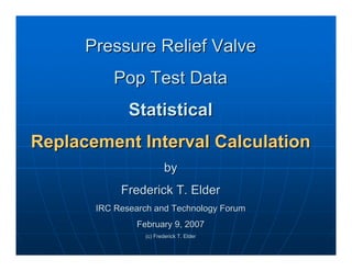
1. Pressure Relief Valve
Pressure Relief Valve
Pop Test Data
Pop Test Data
Statistical
Statistical
Replacement Interval Calculation
by
by
Frederick T. Elder
Frederick T. Elder
IRC Research and Technology Forum
February 9, 2007
February 9, 2007
(c) Frederick T. Elder
2. When to Replace per IIAR 110
When to Replace per IIAR 110
„
„ After a known relief, and within a reasonable time,
After a known relief, and within a reasonable time,
spring
spring-
-loaded relief valves shall be replaced by new
loaded relief valves shall be replaced by new
or remanufactured certified valves. If re
or remanufactured certified valves. If re-
-seating is
seating is
not complete, replacement shall be immediate.
„
„ When a component reliability program is in place to
When a component reliability program is in place to
verify relief valve functionality and longevity by
history, testing, disassembly and inspection, and
periodic statistical review of these activities, relief
valves may be replaced at any interval justified by
the findings of such a program. In the absence of
such a program, each relief valve shall be replaced
at the frequency recommended by the relief valve
manufacturer. In the absence of both a component
reliability program and manufacturers’
recommendations, relief valves shall be replaced
every five years if not indicated earlier at annual
inspection.
inspection.
3. Why Test?
Why Test?
„
„ Properly assess health of NH3
Properly assess health of NH3
refrigeration safety system
„
„ OSHA has required it in prior
OSHA has required it in prior
settlement agreements
„
„ It may save $$$
It may save $$$
„
„ It may answer a PHA question
It may answer a PHA question
6. Background
Background
„
„ Invented by
Invented by Waloddi
Waloddi Weibull
Weibull
in 1937
in 1937 –
– he used it for
he used it for
fatigue life estimation
„
„ Dr. Robert Abernethy the
Dr. Robert Abernethy the
modern Weibull Analysis
expert
expert
„
„ Weibull Analysis first used
Weibull Analysis first used
extensively in aerospace
applications
applications
Waloddi Weibull 1887-1979
7. Advantages of Weibull Analysis
Advantages of Weibull Analysis
„
„ Main advantage:
Main advantage: Small sample size
Small sample size
•
• Samples may be expensive
Samples may be expensive
•
• Reduces time/cost of testing
Reduces time/cost of testing
•
• May not have many recorded failures
May not have many recorded failures
„
„ Weibull Analysis is displayed by an
Weibull Analysis is displayed by an
easy to read graphical plot
8. Pop Test Failure Criteria
Pop Test Failure Criteria
Example – 250 psig valve
Opens at pressures < 242.5 psig – failure
Opens at pressures > 262.5 psig -- failure
9. Alternate Failure Criteria
Alternate Failure Criteria
„
„ Reduce the set pressure of relief
Reduce the set pressure of relief
valves when possible
valves when possible –
– then expand
then expand
failure definition
failure definition
„
„ Do not consider low pressure
Do not consider low pressure
opening a failure for those valves
where that does not create a hazard
10. Weibull Analysis Plot
Weibull Analysis Plot
„
„ Most Weibull Analysis done from plot
Most Weibull Analysis done from plot
„
„ To Plot, you need:
To Plot, you need:
•
• Failure criteria
Failure criteria
•
• Number of failures and times
Number of failures and times
•
• Number of suspensions and times
Number of suspensions and times
„
„ From Plot, you get:
From Plot, you get:
•
• Predicted failure rate
Predicted failure rate
•
• Failure mechanism
Failure mechanism
11. Plotting Data
Plotting Data
„
„ Plot scales
Plot scales
•
• X axis: Age parameter (Units of Hours in Figure)
X axis: Age parameter (Units of Hours in Figure)
•
• Y axis: Cumulative Distribution Function (CDF)
Y axis: Cumulative Distribution Function (CDF)
„
„ Defines percentage of units that will fail up to an age
Defines percentage of units that will fail up to an age.
.
12. Weibayes Analysis
Weibayes Analysis
„
„ Weibayes is used when there
Weibayes is used when there
are no or very few failures:
•
• Finding the MTTF of a unit after
Finding the MTTF of a unit after
initial testing lead to no failures
•
• Redesigned component, several
Redesigned component, several
units tested without failure, is
testing sufficient?
testing sufficient?
•
• Smaller sample sizes needed
Smaller sample sizes needed
with Weibayes since previous
failure history is known
13. Weibayes Analysis
Weibayes Analysis
„
„ Weibayes Analysis equation,
Weibayes Analysis equation,
uses an
uses an assumed
assumed β
β
„
„ Can be used when
Can be used when no failures
no failures
have occurred
have occurred
„
„ Need to have back ground
Need to have back ground
failure info
failure info
•
• Company Weibull library
Company Weibull library
•
• Other
Other Weibull
Weibull libraries
libraries
Where:
Where:
N =
N = total number of
total number of
suspensions and failures
r =
r = number of failed units
number of failed units
β
β =
= assumed slope
assumed slope
t =
t = time or cycles
time or cycles
/
1
N
i
i=1
t
r
β
β
η
⎡ ⎤
= ⎢ ⎥
⎣ ⎦
∑
14. Weibayes Analysis
Weibayes Analysis
„
„ Relief valve failure data
Relief valve failure data
shows typical
shows typical β
β value of
value of 1
1
•
• http://www.barringer1.com/
http://www.barringer1.com/
wdbase.htm
wdbase.htm
„
„ Weibayes can be used to
Weibayes can be used to
determine replacement
interval time
interval time
„
„ Can input data into
Can input data into
Weibull program or
Weibull program or
calculate by hand using
equation
equation
15. Weibayes Analysis
Weibayes Analysis
Determine New Replacement Interval
for Test with Zero Failures
1.
1. Gather suspension data
Gather suspension data
2.
2. Find
Find η
η (as described in next slides)
(as described in next slides)
3.
3. Find k
Find k1
1-
-value from One
value from One-
-Failure Plan
Failure Plan
table for your assumed
table for your assumed β
β and
and
number of samples being tested
4.
4. Replacement Interval =
Replacement Interval =η
η(k
(k1
1)
)
16. Weibayes: Finding
Weibayes: Finding η
η With No Failures
With No Failures
Hand Calculation
Hand Calculation
„
„ Confidence Limit Equation for Zero Failures:
Confidence Limit Equation for Zero Failures:
•
• Use:
Use:
where
where r=# of failures
r=# of failures
T
Ti
i=Time of each replacement
=Time of each replacement
: look up this value from Chi
: look up this value from Chi-
-squared
squared
table for C confidence and 2r+2 degrees of freedom
( )
{ }
2
;2 2
C f
χ ⋅ +
( )
1
2
2 ;2 2 0
i
T C r for r
β
β
η χ
⎧ ⎫
= + ≥
⎨ ⎬
⎩ ⎭
∑
17. Weibayes: Finding
Weibayes: Finding η
η With No Failures
With No Failures
WinSMITH Calculation
„
„ Can Select Specific
Can Select Specific
Confidence
Confidence
•
• Enter number of units, all
Enter number of units, all
as suspensions
as suspensions
•
• Select Weibayes method
Select Weibayes method
•
• Choose specific
Choose specific
confidence,
confidence, 63.2%
63.2%
confidence equivalent to
assuming 1 failure is
imminent
imminent
•
• Find
Find η
η from Weibayes plot
from Weibayes plot
18. Weibayes Example:
Weibayes Example: No Failures
No Failures
During Testing
During Testing
„
„ Parameters: 30 relief valves used for
Parameters: 30 relief valves used for
5 years, 0 failures, want to increase
Replacement Interval
„
„ Question:
Question: How many years can the
How many years can the
valves be used and have at most one
failure with a 90% confidence?
19. Weibayes Example:
Weibayes Example: No Failures
No Failures
During Testing
During Testing
„
„ Data entered in WinSMITH
Data entered in WinSMITH
•
• 30 suspensions, 5 year time
30 suspensions, 5 year time
•
• Weibayes method,
Weibayes method, β
β=1, 90% Confidence
=1, 90% Confidence
η=65.14
20. Weibayes Example:
Weibayes Example: No Failures
No Failures
During Testing
During Testing
„
„ Table of K
Table of K1
1-
-values For One
values For One-
-Failure Test Plans,
Failure Test Plans, β
β=1
=1
„
„ Read N=30, K
Read N=30, K1
1=0.132
=0.132
„
„ Complete table and equation to derive K
Complete table and equation to derive K1
1-
-values
values
included in Appendix B
21. Weibayes Example:
Weibayes Example: No Failures
No Failures
During Testing
During Testing
„
„ Replacement Interval: 65.14(0.132)= 8.6
Replacement Interval: 65.14(0.132)= 8.6
years
years
„
„ So with a 90% confidence, you can replace
So with a 90% confidence, you can replace
the relief valves every 8.6 years and have
at most one failure during that period
„
„ Reasonable approach: 8.6 years minus 5
Reasonable approach: 8.6 years minus 5
years = 3.6 years/2=1.8 years, so add 1.8
years to 5 year zero failure plan to have
reasonable probability of no failures
22. Weibayes Analysis
Weibayes Analysis
Determine New Replacement Interval for
One or More Failures
One or More Failures During Testing
During Testing
„
„ Most Common
Most Common
„
„ Typically, there will be failures
Typically, there will be failures
23. Weibayes Analysis
Weibayes Analysis
Determine New Replacement Interval for
One or More Failures
One or More Failures During Testing
During Testing
1.
1. Gather failure and suspension
Gather failure and suspension
data
data
2.
2. Find
Find η
η (as described in next slides)
(as described in next slides)
3.
3. Find k
Find k0
0-
-value from Zero
value from Zero-
-
Failure Plan table for your
assumed
assumed β
β and number of
and number of
samples being tested
4.
4. Replacement Interval =
Replacement Interval =η
η(k
(k0
0)
)
24. Weibayes: Finding
Weibayes: Finding η
η With Failures
With Failures
Hand Calculation
Hand Calculation
„
„ Use Weibayes equation to find
Use Weibayes equation to find η
η
„
„ Use:
Use:
to get a
to get a specific confidence
specific confidence, where f=# of
, where f=# of
failures
failures
„
„ : look up this value from
: look up this value from
Chi
Chi-
-squared table for C confidence and
squared table for C confidence and
2f+2 degrees of freedom
( )
{ }
1/
2
2
;2 2
c
f
C f
β
η η
χ
⎡ ⎤
⋅
⎢ ⎥
=
⋅ +
⎢ ⎥
⎣ ⎦
( )
{ }
2
;2 2
C f
χ ⋅ +
25. Weibayes: Finding
Weibayes: Finding η
η With Failures
With Failures
Hand Calculation
Hand Calculation
„
„ Chi
Chi-
-Squared Table, C: 90% Confidence
Squared Table, C: 90% Confidence
26. Weibayes: Finding
Weibayes: Finding η
η With Failures
With Failures
WinSMITH Calculation
„
„ Enter number of failures, all
Enter number of failures, all
with the assumed time of
half the usage time
half the usage time
„
„ Enter number of suspensions
Enter number of suspensions
„
„ Choose the specific
Choose the specific
confidence
confidence
„
„ Find
Find η
η from the Weibayes
from the Weibayes
plot
plot
27. Weibayes Example:
Weibayes Example: One or More
One or More
Failures
Failures During Testing
During Testing
„
„ Parameters: 30 relief valves used for
Parameters: 30 relief valves used for
5 years, 2 failures, don’t know when
failures occurred
failures occurred
„
„ Question:
Question: How many years can the
How many years can the
valves be used and have zero
failures with a 90% confidence?
28. Weibayes Example:
Weibayes Example: One or More
One or More
Failures
Failures During Testing
During Testing
„
„ Data entered in WinSMITH
Data entered in WinSMITH
•
• 28 suspensions, 5 year time
28 suspensions, 5 year time
•
• 2 failures, assumed half of 5 years, or 2.5 years
2 failures, assumed half of 5 years, or 2.5 years
•
• Weibayes method,
Weibayes method, β
β=1, 90% Confidence
=1, 90% Confidence
27.26
η =
29. Weibayes Example:
Weibayes Example: One or More
One or More
Failures
Failures During Testing
During Testing
„
„ Table of K
Table of K0
0-
-values For Zero
values For Zero-
-Failure Test Plans,
Failure Test Plans, β
β=1
=1
„
„ Read N=30, K
Read N=30, K0
0=0.077
=0.077
„
„ Complete table and equation to derive K
Complete table and equation to derive K0
0-
-values
values
included in Appendix B
30. Weibayes Example:
Weibayes Example: One or More
One or More
Failures
Failures During Testing
During Testing
„
„ Replacement Interval:
Replacement Interval:
27.26(0.077)= 2.1 years
„
„ So with a 90% confidence, you can
So with a 90% confidence, you can
replace the relief valves every 2.1 years
and have no failures during the interval
31. Remember
Remember
„
„ MI of pipes and vessels is also of high priority
MI of pipes and vessels is also of high priority
„
„ Relief Valves not to be placed back in service
Relief Valves not to be placed back in service
after testing
after testing
„
„ Need judgment to extend the replacement/test
Need judgment to extend the replacement/test
interval
interval
„
„ Failed relief valve may never be needed
Failed relief valve may never be needed
32. Where to Buy Weibull Material
Where to Buy Weibull Material
„
„ The New Weibull Handbook and the
The New Weibull Handbook and the
WinSMITH software packages can be
purchased at:
purchased at:
•
• http://
http://www.weibullnews.com/contents.h
www.weibullnews.com/contents.h
tm#Prices
tm#Prices
33. Sources
Sources
„
„ Engineering Safety Relief Systems
Engineering Safety Relief Systems, March 2006.
, March 2006.
by Reindl, D.T, Jekel, T.B., Available from the
Industrial Refrigeration Consortium
„
„ The New Weibull Handbook
The New Weibull Handbook, Fourth Edition, 2000,
, Fourth Edition, 2000,
by Robert Abernethy
by Robert Abernethy
„
„ The New Weibull Handbook
The New Weibull Handbook, Fifth Edition, 2006,
, Fifth Edition, 2006,
by Robert Abernethy
by Robert Abernethy
„
„ Fitness for Service of Pressure Relieving Systems
Fitness for Service of Pressure Relieving Systems,
,
by W. E. Short II, presented at The 2003 ASME
Pressure Vessels and Piping Conference
„
„ Reliability Testing of Relief Valves
Reliability Testing of Relief Valves, by Robert E.
, by Robert E.
Gross, presented at The 2004 ASME Pressure
Vessels and Piping Conference
34. Sources
Sources
„
„ Plant Guidelines for Technical Management of
Plant Guidelines for Technical Management of
Chemical Process Safety
Chemical Process Safety, pp 169
, pp 169-
-172, by Center
172, by Center
for Chemical Process Safety, 1992
„
„ Armor Swift
Armor Swift Eckrich
Eckrich –
– OSHA settlement
OSHA settlement
agreement of October 9, 1997
„
„ IBP
IBP –
– OSHA settlement agreement of 2001
OSHA settlement agreement of 2001
„
„ Code Requirements for Safety Relief Systems
Code Requirements for Safety Relief Systems,
,
Todd Jekel, 2005 Research and Technology
Forum, January 20, 2005
35. Sources
Sources
„
„ Center for Chemical Process Safety (1998).
Center for Chemical Process Safety (1998).
Guidelines for Pressure Relief and Effluent
Handling Systems
Handling Systems. (pp. 104
. (pp. 104-
-107). Center for
107). Center for
Chemical Process Safety/
Chemical Process Safety/AIChE
AIChE. Online version
. Online version
available at: http://www.knovel.com/knovel2/
Toc.jsp?BookID
Toc.jsp?BookID=831&VerticalID=0
=831&VerticalID=0
„
„ Center for Chemical Process Safety (1989).
Center for Chemical Process Safety (1989).
Process Equipment Reliability Data with Data
Tables
Tables. P 212
. P 212
37. Advantages of Weibull Analysis
Advantages of Weibull Analysis
„
„ Weibull Analysis
Weibull Analysis
can be used for:
can be used for:
•
• Failure Distribution
Failure Distribution
•
• Failure Forecasts
Failure Forecasts
and Predictions
and Predictions
•
• Maintenance
Maintenance
Planning
Planning
•
• Effectiveness of a
Effectiveness of a
Redesign
Redesign
38. Weibull Analysis Software
Weibull Analysis Software
„
„ WinSMITH Weibull from Fulton
WinSMITH Weibull from Fulton
Findings
Findings
•
• http://www.barringer1.com/wins.htm
http://www.barringer1.com/wins.htm
„
„ Created by Wes Fulton and Dr. Bob
Created by Wes Fulton and Dr. Bob
Abernethey
Abernethey
39. Weibull Analysis Software
Weibull Analysis Software
„
„ Enter age data, suspensions and failures
Enter age data, suspensions and failures
„
„ Software will:
Software will:
•
• Plot Data
Plot Data
•
• Calculate
Calculate Eta
Eta, Beta, and PVE numbers
, Beta, and PVE numbers
•
• Run a distribution analysis
Run a distribution analysis
•
• Generate a results report
Generate a results report
40. Plotting Data
Plotting Data
„
„ Age must be known for data
Age must be known for data
•
• Standard Life Data: exact age of parts
Standard Life Data: exact age of parts
known
known
•
• Interval Data: Age of parts not exactly
Interval Data: Age of parts not exactly
know, so parts are grouped
„
„ Could be from weekly, monthly, etc
Could be from weekly, monthly, etc
inspections
inspections
„
„ Age may be operating time,
Age may be operating time,
starts/stops, etc.
starts/stops, etc.
41. Plotting Data
Plotting Data
„
„ Failures
Failures
•
• Establish failure mode
Establish failure mode
•
• Every part displaying
Every part displaying
this mode constitutes a
failure
failure
„
„ Suspensions
Suspensions
•
• Parts that failed via a
Parts that failed via a
different mode
different mode
•
• Parts that have not yet
Parts that have not yet
failed
failed
„
„ Early Suspension: Age
Early Suspension: Age
below age of first
below age of first
failure
failure
„
„ Late Suspension: Age
Late Suspension: Age
above age of last
above age of last
failure
failure
42. Plotting Data
Plotting Data
„
„ Plot scales
Plot scales
•
• X axis: Age parameter (Units of Hours in Figure)
X axis: Age parameter (Units of Hours in Figure)
•
• Y axis: Cumulative Distribution Function (CDF)
Y axis: Cumulative Distribution Function (CDF)
„
„ Defines proportion of units that will fail up to an age as a
Defines proportion of units that will fail up to an age as a
percentage
percentage
44. Plotting Data
Plotting Data
„
„ Two
Two-
-parameter most widely used Weibull
parameter most widely used Weibull
distribution
distribution
„
„ CDF
CDF (Cumulative Distribution Function):
(Cumulative Distribution Function):
F(t
F(t) = 1
) = 1-
- e
e-
-(t
(t/
/η
η)
)β
β
•
• F(t
F(t) = fraction failing up
) = fraction failing up-
-to
to-
-time t
time t
•
• t= failure time
t= failure time
•
• η
η = characteristic life
= characteristic life
•
• e = 2.718281, the base for natural logarithms
e = 2.718281, the base for natural logarithms
•
• β
β = slope parameter
= slope parameter
45. Plotting Data on Weibull Paper
Plotting Data on Weibull Paper
„
„ Arrange failures and suspensions in time ascending
Arrange failures and suspensions in time ascending
order
order
„
„ Set up the following table:
Set up the following table:
„
„ Fill in Rank and Reverse Rank, and in Time column,
Fill in Rank and Reverse Rank, and in Time column,
include whether it was a Suspension or Failure
„
„ If two data points have the same time to failure, they
If two data points have the same time to failure, they
are both presented in the column, and they will both
get median rank values
46. Plotting Data on Weibull Paper
Plotting Data on Weibull Paper
„
„ Use equation to get Adjusted Rank (A.R.):
Use equation to get Adjusted Rank (A.R.):
A.R.=[Reverse Rank X Previous Rank + (N+1)] / [Reverse Rank + 1]
„
„ Use
Use Benard’s
Benard’s Median Rank formula to get
Median Rank formula to get
new Median Rank (since adjusted rank is
not an integer):
not an integer):
Benard’s
Benard’s M.R.=(i
M.R.=(i-
-0.3) X 100 / (N+0.4)
0.3) X 100 / (N+0.4)
„
„ Fill out previous table, and plot:
Fill out previous table, and plot:
•
• Benard’s
Benard’s M. R. on the y
M. R. on the y-
-axis
axis
•
• Time on x
Time on x-
-axis
axis
„
„ Draw a best fit line through the points,
Draw a best fit line through the points,
make sure it is 1:1 Weibull paper
47. Weibull Example:
Weibull Example: Preparing
Preparing
Weibull Plot by Hand
„
„ Parameters: You are given the
Parameters: You are given the
following data, 8 total parts, 5
failures at 49,82,96,30, and 90 hours
and, 3 suspensions at 45,10, and
100 hours
100 hours
„
„ Question:
Question: At how many hours can
At how many hours can
you expect approximately 50% of
the parts to fail?
the parts to fail?
48. Weibull Example:
Weibull Example: Preparing
Preparing
Weibull Plot by Hand
„
„ Set up and fill in table:
Set up and fill in table:
„
„ Plot the points on 1:1 Weibull Paper
Plot the points on 1:1 Weibull Paper
„
„ Draw a best fit line through the points and
Draw a best fit line through the points and
draw a line across from the 50% mark and
down to the time axis
49. Weibull Example:
Weibull Example: Preparing
Preparing
Weibull Plot by Hand
50% fail by 77 hours
50. Interpreting the Plot
Interpreting the Plot
„
„ PVE %: Goodness of fit indicator for
PVE %: Goodness of fit indicator for
Weibull line
Weibull line
•
• 10% is acceptable, 50% is average
10% is acceptable, 50% is average
„
„ N/S: Total number of data points/ Number
N/S: Total number of data points/ Number
of Suspensions
of Suspensions
Eta, Beta, PVE,
and N/S
51. Interpreting the Plot
Interpreting the Plot
„
„ Eta
Eta -
- Characteristic life: Age at which
Characteristic life: Age at which
63.2% of parts will fail
•
• Parameter most effected by suspensions
Parameter most effected by suspensions
52. Interpreting the Plot
Interpreting the Plot
„
„ Beta
Beta –
– Slope of Weibull line: Failure Mode
Slope of Weibull line: Failure Mode
•
• Beta < 1.0 indicates infant mortality
Beta < 1.0 indicates infant mortality
•
• Beta = 1.0 indicates random failures that are
Beta = 1.0 indicates random failures that are
independent of age
independent of age
•
• Beta > 1.0 indicates wear out failures
Beta > 1.0 indicates wear out failures
53. Interpreting the Plot
Interpreting the Plot
„
„ Use PVE number to evaluate fit of
Use PVE number to evaluate fit of
line
line
„
„ Use Beta to evaluate failure method
Use Beta to evaluate failure method
„
„ Look for “Bad” Weibull characteristics
Look for “Bad” Weibull characteristics
54. Bad Weibull
Bad Weibull
„
„ Curved Weibull data
Curved Weibull data
•
• Origin not at t=0, must
Origin not at t=0, must
use three
use three-
-parameter
parameter
Weibull
Weibull
„
„ Outlying data points
Outlying data points
•
• Look at engineering
Look at engineering
aspects of data
aspects of data
recording, test records,
calibrations, etc.
calibrations, etc.
„
„ Two different slopes of
Two different slopes of
Weibull data
Weibull data
•
• More than one failure
More than one failure
mode represented by
mode represented by
data, try to separate
data
data
55. Bad Weibull
Bad Weibull
„
„ Close Serial Numbers
Close Serial Numbers
•
• Batch problem
Batch problem
„
„ If PVE number is unacceptable
If PVE number is unacceptable
•
• Look to different distributions, Log
Look to different distributions, Log
normal, Three
normal, Three-
-parameter Weibull
parameter Weibull
„
„ Careful, few data points leads to high
Careful, few data points leads to high
PVE number
PVE number
56. Failure Forecasting
Failure Forecasting
„
„ Expected number of
Expected number of
failures that may
failures that may
occur in a specific
occur in a specific
period of time
period of time
„
„ Predicts:
Predicts:
•
• Future failures when
Future failures when
failed units are replaced
•
• Future failures when
Future failures when
failed units are not
replaced
replaced
57. Failure Forecasting
Failure Forecasting
„
„ Additional input needed:
Additional input needed:
•
• Age of components in service
Age of components in service
•
• Usage rate
Usage rate
•
• Introduction rate of new units
Introduction rate of new units
•
• Failed parts replacement info
Failed parts replacement info
59. Weibayes: Finding
Weibayes: Finding η
η With No Failures
With No Failures
Hand Calculation
Hand Calculation
„
„ Assume at Least One Failure is Imminent:
Assume at Least One Failure is Imminent:
•
• Use Weibayes equation to find
Use Weibayes equation to find η
η
•
• Assume 1 failure (r=1) since a failure is
Assume 1 failure (r=1) since a failure is
imminent (yields 63% confidence)
•
• Use the following table to achieve different
Use the following table to achieve different
confidences:
confidences:
60. Zero Failure Plan Table,
Zero Failure Plan Table, β
β = 1
= 1
„
„ K=[(
K=[(-
-1/N)*ln(0.1)]
1/N)*ln(0.1)](1/
(1/β
β)
)
61. Chi Squared Table for Use With
Chi Squared Table for Use With
Weibayes Hand Calculations
„
„ Use 0.10 column for 90% Lower Bound,
Use 0.10 column for 90% Lower Bound,
0.05 for 95% Lower Bound, etc.
62. One
One-
-Failure Test Plan Table,
Failure Test Plan Table, β
β = 1
= 1
„
„ (1
(1-
-Confidence)=(
Confidence)=(e
e-
-(k
(k)
)β
β
)
)N
N+N(e
+N(e-
-(k
(k)
)β
β
)
)N
N-
-1
1(1
(1-
- e
e-
-(k
(k)
)β
β
)
)