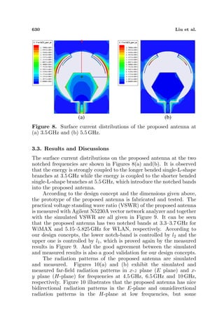
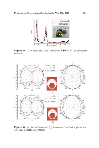
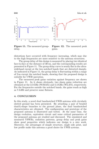
This document summarizes a research paper that proposes a new dual band-notched ultra-wideband (UWB) antenna. The antenna uses a pair of bent dual-L-shaped parasitic branches attached to a circular slotted ground plane to create notched bands at 3.3-3.7 GHz for WiMAX and 5.15-5.825 GHz for WLAN. The lengths and positions of the branches were optimized to achieve the desired notch frequencies. Simulated and measured results showed good agreement and that the antenna has good radiation patterns and time-domain performance, making it suitable for modern UWB communication systems.
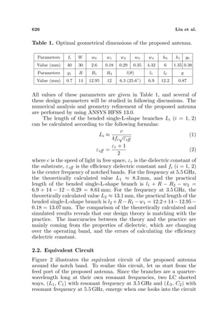
![Progress In Electromagnetics Research, Vol. 136, 623–634, 2013
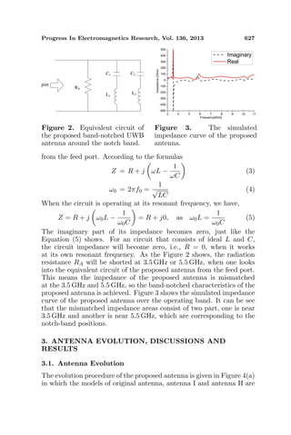
A CPW-FED DUAL BAND-NOTCHED UWB ANTENNA
WITH A PAIR OF BENDED DUAL-L-SHAPE PARASITIC
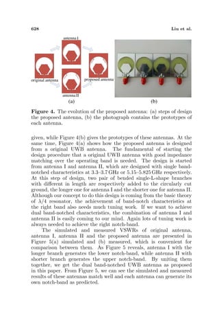
BRANCHES
Xianglong Liu*, Yingzeng Yin, Pingan Liu, Junhui Wang,
and Bin Xu
National Key Laboratory of Science and Technology on Antennas and
Microwaves, Xidian University, Xi’an, Shaanxi 710071, China
Abstract—In this paper, a novel coplanar waveguide (CPW) fed
dual band-notched ultra-wideband (UWB) antenna with circular
slotted ground is proposed. In order to achieve two notched bands
at 3.3–3.7 GHz for worldwide interoperability for microwave access
(WiMAX) and 5.15–5.825 GHz for wireless local area network (WLAN)
respectively, a pair of bended dual- L-shape branches are attached
to the slotted ground. By optimizing the lengths and positions of
the branches, the desired notch-bands of WLAN and WiMAX can be
achieved. The prototype of the proposed antenna was fabricated and
tested. The simulated and measured results show good agreement
over the ultra-wideband. Besides these mechanical features, such
as compact in size, easy in fabrication, the proposed antenna also
shows good characteristics in its radiation patterns and time-domain
behaviors. So it is a nice candidate for modern UWB communication
systems.
1. INTRODUCTION
Since the Federal Communications Commission (FCC) released the
unlicensed frequency band of 3.1–10.6 GHz for commercial UWB
applications [1], ultra-wideband (UWB) systems have drawn lots of
interests for their high data rates, great capacity, low complexity
and low operating power level [2]. The UWB systems are usually
used in home networking systems as a convenient way for personal
wireless communications. As one of the most essential parts of the
Received 25 December 2012, Accepted 25 January 2013, Scheduled 27 January 2013
* Corresponding author: Xianglong Liu (xianglongliu007@163.com).](https://image.slidesharecdn.com/36-150224075415-conversion-gate01/85/36-12122507-2-1-320.jpg)
![624 Liu et al.
UWB systems, UWB antennas have drawn attention of researchers.
But when UWB systems bring us conveniences, they also carry us
problems at the same time. One problem is the interference between
the UWB systems and other communication systems such as local
area network (WLAN, 5.15–5.825 GHz), worldwide interoperability for
microwave access (WiMAX, 3.3–3.7 GHz) IEEE802.11a in the United
States (5.15–5.35 GHz, 5.725–5.825 GHz) and HIPERLAN/2 in Europe
(5.15–5.35 GHz, 5.47–5.725 GHz) [3]. So UWB antennas with band-
notched characteristics at these existing bands are needed.
Among recent researches, many UWB antennas with band-
notched characteristics have been proposed and studied. The
conventional and effective way to achieve the notch-band is inserting
a slit on the patch [4–10]. While there are also many other ways to
create band-notched characteristics on a UWB antenna, such as using
parasitic structures [11–18], embedding a slit in the feeding strip [19],
or adding split ring resonator (SRR) coupled to the feed-line [20, 21].
These slots or slits are in different shapes, such as L-shape [5, 12, 20],
T-shape [7, 16, 17], C-shape [8, 9, 11, 13, 15, 18, 19] and etc., but the
common point they all share is to introduce a perturbation into the
UWB antennas. All these shapes are near λ/2 or λ/4 resonant lengths
corresponding their notched frequencies, so in band-notched antennas
designing procedures, appropriate slotcoupling and resonant length are
very important.
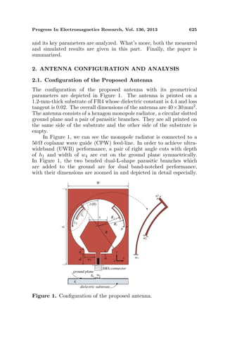
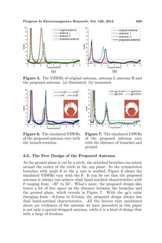
In this study, a new UWB monopole antenna with notched band
at 3.3–3.7 GHz (WLAN) and 5.15–5.825 GHz (WiMAX) is developed.
The original UWB antenna is mainly composed of a hexagon radiation
patch and a circular slotted ground plane. In order to obtain
band-notched characteristics at 3.3–3.7 GHz and 5.1–5.8 GHz, a pair
of bended dual-L-shape branches are added to the slotted ground
symmetrically. Also, one branch consists of two strips which different
in length, but this two strips share a common circle center. The
different strip controls different notch-band, the longer strip for the
lower notch-band and the shorter one for the upper notch-band. Some
key parameters which affect the characteristics of the notch bands are
specially studied. Finally, the proposed antenna is designed, fabricated
and tested. The simulated and measured results are also compared and
discussed which shows the theoretical analysis and the practice are
match well. The proposed antenna has stable radiation pattern and
nice omni-directional performances across the whole operating band,
which validates our design concept and theoretical analysis.
This paper mainly consists of three parts. First, the configuration
of the proposed antenna is given and the equivalent circuit of the
antenna is proposed and discussed. Secondly, the antenna evolution](https://image.slidesharecdn.com/36-150224075415-conversion-gate01/85/36-12122507-2-2-320.jpg)