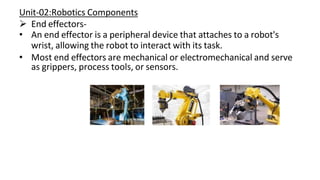
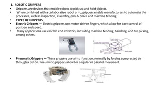
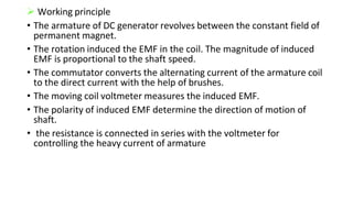
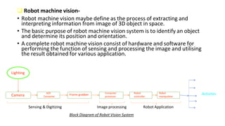
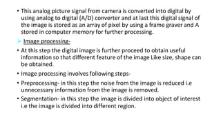
Robotics
Lec-15
Vijay sir
Unit-02:Robotics Components
 End effectors-
• An end effector is a peripheral device that attaches to a robot's
wrist, allowing the robot to interact with its task.
• Most end effectors are mechanical or electromechanical and serve
as grippers, process tools, or sensors.
1. ROBOTIC GRIPPERS
• Grippers are devices that enable robots to pick up and hold objects.
• When combined with a collaborative robot arm, grippers enable manufacturers to automate the
processes, such as inspection, assembly, pick & place and machine tending.
• TYPES OF GRIPPERS
• Electric Grippers — Electric grippers use motor-driven fingers, which allow for easy control of
position and speed.
• Many applications use electric end effectors, including machine tending, handling, and bin picking,
among others.
• Pneumatic Grippers — These grippers use air to function, normally by forcing compressed air
through a piston. Pneumatic grippers allow for angular or parallel movement.
• Suction Cups — Suction cups use a vacuum to pick up parts. Their simple design offers ample flexibility
for material handling, along with cost-effectiveness. However, they are unable to handle perforated
materials.
• Magnetic Grippers — These grippers feature a design that’s similar to suction cups, but they’re used
specifically for handling ferrous material. Additionally, they eliminate the risk of dropping materials during
power outages or air loss. Their simple design also requires minimal maintenance.
• Mechanical Grippers — Non-powered mechanical grippers normally feature designs for specific
types of parts. These grippers may include forks, hooks, or complex fingers that allow operators
to clamp and rotate them.
2. ROBOTIC PROCESS TOOLS
• Robotic Welding — Applications often use robot arms with welding end effectors,
which are most frequently found in the automotive industry. Because of their
precision and consistency, robotic welding systems usually produce great results.
• Painting — The application of paint must be consistent and smooth, which often
presents a challenge for human operators. In addition, these applications must protect
against contamination in a controlled environment. Both of these factors make painting
robots suitable for these conditions, allowing for high-quality paintwork while reducing
the risk of contamination.
3. ROBOTIC SENSORS
• Some applications also connect sensors to robots, converting them
into programmable sensor-orientation devices.
• Robotic inspection and other applications use these to minimize
inspection engineers’ hands-on time they would otherwise spend
gathering data.
• Applications for End Effectors-
 PICK & PLACE
• These tasks involve picking up and placing objects in another location.
• these applications require safe handling and precision when manipulating the object, regardless of the object’s
material or its fragility.
 MACHINE TENDING
• Machine tending entails overseeing equipment as it loads and unloads machines. It could also involve blow off,
part inspection, sorting and packaging, and wash tasks.
 PACKAGING & PALLETIZING PROCESSES
• These processes include high-speed and precision packaging assembly, pallet forming, and product loading,
among other tasks.
 ASSEMBLY TASKS
• Assembly is a manufacturing process in which machinery assembles products by adding individual components
one at a time in a specific sequence. In completing these tasks, the robot’s or manipulator’s end effector
frequently handles objects of various shapes and sizes.
 QUALITY TESTING & INSPECTION
• Following the manufacturing process, products require the application of consistent force and rigorous testing.
While human workers may struggle to maintain consistent tension, pressure, and overall precision, it’s easy to
program these tasks when using robotics with the appropriate end effectors.
 SURFACE FINISHING
• Surface finishing tasks require adequate flexibility, which robotics and end effectors help achieve.
• surface finishing is a particularly dirty task in the production process, it’s also ideal for automating with the right
programmable machinery.
Robotics
Lec-16
Vijay sir
 Sensing and feedback device-
• An electronics device that transfer the physical phenomenon into electrical signal
is known as sensor.
• Feedback sensors are used to detect your mechanical device's output so that
your control system can adjust based on external factors.
• Feedback devices are a class of device required for closed loop operation. They
provide a signal back to the drive or motion controller to monitor an operation or
process and verify that proper operation occurs.
 Features of sensors-
• Wide operating range
• Response time should be very minimum
• Accuracy should be high as possible
• It should have good sensitivity
• Good repeatability of any type of work
• Its cost should be low
• Its size should be small
 Types of sensor
The sensor are classified as follow
1. Tactile sensor(Contact sensor)
2. Non-Tactile sensor (contactless sensor)
 Tactile sensor – the sensor which must be brought in contact with the object to
obtain signal to measure the necessary quantity is known as tactile sensor.
• When the tactile sensor make a contact with object then and electrical signal is
generated and send to the robot controller.
• the electrical signal is obtained through the contact of microswitches.
• Examples of tactile sensor are piezoelectric crystal, potentiometer, LVDT
 Non- Tactile sensor –
• The sensor which sends the signal without any contact is known as non-
tactile or contactless sensor.
• It operates or sense the signal only within the specified range of distance
from the object.
• This type of sensor uses magnetic field, ultraviolet light, infrared light
ultrasonic wave or electromagnetic wave to sense and measure the desire
quantity.
• Example of contactless sensor are proximity sensor, ultrasonic sensor etc
 Types of sensor used in robotics
• Internal sensor
• External sensor
 Internal sensor-
• it is the sensor which is used to measure position, velocity, acceleration of robot joint or end effector .
• It is also known as feedback device or sensor
 The following devices is under the category of internal sensor
• Potentiometer
• Differential transformer
• DC tachometer
• Optical encoder
 External sensor-
• the sensor used to monitor the robot geometric and dynamic relation to its task environment or the object
that it is handling.
 Following sensor under the category of external sensor
• strain gauge
• Proximity device
• Ultrasonic sensor

Lec-17
 Potentiometer
• Potentiometer is the simple device which is used to measure the
position of object.
• Potentiometer are analog device whose output voltage is
proportional to the position(angular or linear) of a object.
• It may be either angular or linear.
• Construction and working of potentiometer-
• Potentiometer is made by using a winding of resistive element in a coil
form.
• By applying a DC voltage across the entire resistance the output voltage is
proportional to the linear or rotary distance of sliding contact from
reference point.
• When it is used in robotics the coil is mounted over the input link and the
sliding contact is connected with the output link and then it rotate or slide,
the value of r varies thus output voltage and this variation can be measure
to find the position of output link with respect to the input link.
• It is used as a primary position monitoring sensor where extreme accuracy
is not needed.
 Linear variable differential transformer(LVDT)-
• LVDT is another type of position sensor which is used to find the
position of different link.
• Construction –
• It consist of one primary winding and two secondary winding which
are placed on either side of the same magnetic core . the magnetic
core is free to move axially inside the coil assembly.
• Working –
• When the core is in centre The induced voltage are equal and opposite.
hence they cancel out each other and the output voltage is zero.
• When the external applied force move the core towards coil S2, voltage E2
is increased but E1 is decreased and still is in antiphase to each other so
resultant voltage in secondray is Vo= E2-E1 and is in phase with E2.
• When the moveable core moves towards coil S1, Vo= E1-E2 and is in phase
with E1.
• Thus magnitude of output voltage is the function of distance moved by the
core and its polarity or phase indicates that in which direction it has
moved.
• In robot the core is attached with moving objects and magnitude of output
voltage gives the position of that objects.
• LVDT is usually used where exact linear motion is performed.
Robotics
Lec-18
Vijay sir
 Optical Encoder
• The optical encoder is a transducer commonly used for measuring
rotational motion.
• It consists of a shaft connected to a circular disc, containing one or
more tracks of alternating transparent and opaque areas.
• A light source and an optical sensor are mounted on opposite sides of
each track.
• Optical encoder are non contact device which give digital signal
directly.
• it is one of the most widely used position sensor.
• Optical sensor are available both in linear and rotary configuration but
the rotary configuration is almost exclusively used in robotic
application.
 Construction –
• the optical encoder consist of three basic component : light source, rotary or translatory disc, and a
sensor.
• A light source is an incandescent lamp or infrared light emitting diode(LED).
Rotary or translatory disc is a type of disc which has alternate opaque and transparent sector which
are developed by means of photographic process on a plastic disc or slots are cut on a metal disc.
• A sensor is a photodiode or phototransister which sense the light
passing through sector or slot of disc.
Working –
• The disc of the encoder is connected to the motor shaft and rotates with
motor
• The disc rotation permit the light to reach the sensor when ever the
transparent slot comes in front of LED there by generating a series of
pulses and output of sensor.
• These pulse are then fed to a counter which count the number of pulse and
these count is the measure of angle through which shaft has moved.
• The speed of shaft is also obtained by sampling the count at regular
interval by means of clock pulse.
Robotics
Lec-19
Vijay sir
 DC Tachometer
• The tachometer is used for measuring the rotational speed or angular velocity of the
machine which is couple to it.
• it works on the principal of relative motion between magnetic field and shaft of the
couple device.
• the relative motion induces and EMF in the coil which is placed between the magnetic
field of the permanent magnet .
• The developed EMF is directly proportional to the speed of shaft.
 Construction
• It consist of a permanent magnet,
armature , commutator, brushes , variable
resister and a moving coil voltmeter.
• the machine is to be measured is couple
with the soft of the DC tachometer
generator
 Working principle
• The armature of DC generator revolves between the constant field of
permanent magnet.
• The rotation induced the EMF in the coil. The magnitude of induced
EMF is proportional to the shaft speed.
• The commutator converts the alternating current of the armature coil
to the direct current with the help of brushes.
• The moving coil voltmeter measures the induced EMF.
• The polarity of induced EMF determine the direction of motion of
shaft.
• the resistance is connected in series with the voltmeter for
controlling the heavy current of armature
Robotics
Lec-20
Vijay sir
 Strain guage-
• Strain gauge is a resister used to measure a strain of an object.
• when an external force is applied due to which there is a deformation
occurs in the shape of object.
• This deformation in the shape is both compressive or tensile is called
strain and it is measured by strain gauge.
• When an object deform with in the limit of elasticity then it either
becomes narrow and longer or It becomes shorter and broaden. as
result of it, there is a change in resistance occurs.
 Construction –
• The change in resistance normally
has very small value and to sense
that small change, strain guage has
a long thin metallic strip arrange in
a zig-zag form on a non conducting
material called the carrier.
• The guage is glued on the device by
an adhesive.
• strain gauge uses a bridge circuit
which shows the measured stress
by the degree of discrepancy and
uses a voltmeter in the centre of
the bridge to provide an accurate
measurement of that unbalance.
• In this circuit, R1 and R3 are the ratio
arms equal to each other and R2 is
the rheostat arm has a value equal to
the strain gauge resistance.
• when the gauge is unstrained, the
bridge is balanced and voltmeter
reading shows zero value.
• As there is a change in resistance of
strain guage, the bridge gets
unbalanced and producing an
indication in voltmeter.
• The output voltage from the bridge
can be amplified further by a
differential amplifier.
Robotics
Lec-21
Vijay sir
 Proximity sensor-
• Proximity sensor is a non contact sensor which generally has binary
output that indicates the present of an object at a specified distance.
 There are following types of proximity sensor commonly used in
robotics.
1. Optical proximity sensor
2. Ultrasonic sensor
1. Optical proximity sensor
• Optical proximity sensor is a device that uses the principal of reflected
infrared or visible light to measure a small distance in a robotic
system or sense the presence of object in front of it.
• Optical proximity sensor consist of a transmitter and receiver
• transmitter circuit consist of a photo transmitter LED that sends the
light out by converting electrical energy into light.
• This light gets reflected from the targeted object which is received by
the photo receiver ( photodiode).
2. Ultrasonic proximity sensor-
• Ultrasonic proximity sensor work by using sound
frequency higher than the audible limit of human
hearing(ultrasonic wave around 20kHz) typically in
the range of 25 to 50 kHz.
• The basic principle of ultrasonic sensor is that the
sensor sends out an ultrasonic pulse using an
electrocoustic transducer and receives a pulse back.
• Using the time difference between the sent and
received signal, the distance of an object can be
determine as well as object detection can be done.
• A common design is to build both the transmitter
and the receiver into the same housing but they can
also be house in separate unit if needed.
• Ultrasonic proximity sensor use sound rather than light so that they
can be used where photoelectric sensor have difficulty such as in
detecting clear plastic object.
Robotics
Lec-22
 Thermocouple-
• A thermocouple is sensor that measures the temperature.
• It consist of two wire legs made from different material.
• The wires legs are welded together at one end creating a junction.
• When the junction of two material in heated or cold a voltage is created
that can be correlated with temperature.
• Thermocouple materials include copper/constantan, iron/ constantan, and
chromel/alumel.
 Thermistor –
• The thermistor is a temperature sensing
device whose resistance is a function of its
temperature.
• Thermistor are available in two types-
1. PTC (positive temperature coefficient)
2. NTC (negative temperature coefficient)
• The resistance of a positive temperature
coefficient(PTC) thermistor increases as the
temperature increases where as the
resistance of negative temperature
coefficient(NTC) thermistor decrease as
temperature increases and this type seems
to be most commonly used thermistor
Lec-23
 Resistive temperature detector ( RTD)-
• Resistive temperature detector is also known
as resistance thermometer.
• RTD are similar to thermistor in which
resistance change with temperature.
• It uses a special material that is sensitive to
temperature change .
• RTD use a coil of wire wound around a core
made from ceramic or glass.
• The RTD wire is of pure material.
• generally it is of platinum, nickel or copper
and the material has an accurate resistance-
temperature relation which is used to
determine the measured temperature.
 Piezoelectric sensor –
• Piezoelectric sensor are used to measure force
and pressure applied by a robotic gripper.
• It work on the principle of piezoelectric effect.
• Piezoelectric effect is the phenomenon in
which when a material is pressed it will
produce an electric voltage and the intensity of
voltage indicate the amount of force or
pressure applied.
• Quartzs is widely used as a piezoelectric
material in this type of sensor.
Robotics
Lec-24
 Robot machine vision-
• Robot machine vision maybe define as the process of extracting and
interpreting information from image of 3D object in space.
• The basic purpose of robot machine vision system is to identify an object
and determine its position and orientation.
• A complete robot machine vision consist of hardware and software for
performing the function of sensing and processing the image and utilising
the result obtained for various application.
Lighting
Camera
A/D
Converter
Frame grabber Computer
processor
Robot
controller
Robot
manipulator
Activites
Sensing & Digitizing Image processing Robot Application
Block Diagram of Robot Vision System
The operation of robot machine vision consist of following three
steps
• Sensing and digitising
• Image processing and analysis
• Application
 Sensing and digitising-
• In this step first of all an image is captured by using a light source,
which illuminate the object and camera which then capture the image
of an object.
• The image form in the camera is converted into analog signal
(Voltage) with the help of suitable transducer present inside the
camera.
• This analog picture signal from camera is converted into digital by
using analog to digital (A/D) converter and at last this digital signal of
the image is stored as an array of pixel by using a frame graver and A
stored in computer memory for further processing.
 Image processing-
• At this step the digital image is further proceed to obtain useful
information so that different feature of the image Like size, shape can
be obtained.
• Image processing involves following steps-
• Preprocessing- in this step the noise from the image is reduced i.e
unnecessary information from the image is removed.
• Segmentation- in this step the image is divided into object of interest
i.e the image is divided into different region.
• Description- In this steps the object of interest is examined and
different feature of image like shape, size, edge etc is obtained which
help to differentiate one object from another.
• Part recognization- in this step the unique identification of each
object in the image is done by image comparison technique. the
image of known object are stored in the computer and the region
identified in the image are compared with these to recognise the part
in the image. this method is known as template matching.
 Application-
The current application of robot vision include
• inspection
• part identification
• location and orientation.

ROBOTICS polytechnic notes 5th sem.pptx

  • 1.
  • 2.
    Unit-02:Robotics Components  Endeffectors- • An end effector is a peripheral device that attaches to a robot's wrist, allowing the robot to interact with its task. • Most end effectors are mechanical or electromechanical and serve as grippers, process tools, or sensors.
  • 3.
    1. ROBOTIC GRIPPERS •Grippers are devices that enable robots to pick up and hold objects. • When combined with a collaborative robot arm, grippers enable manufacturers to automate the processes, such as inspection, assembly, pick & place and machine tending. • TYPES OF GRIPPERS • Electric Grippers — Electric grippers use motor-driven fingers, which allow for easy control of position and speed. • Many applications use electric end effectors, including machine tending, handling, and bin picking, among others. • Pneumatic Grippers — These grippers use air to function, normally by forcing compressed air through a piston. Pneumatic grippers allow for angular or parallel movement.
  • 4.
    • Suction Cups— Suction cups use a vacuum to pick up parts. Their simple design offers ample flexibility for material handling, along with cost-effectiveness. However, they are unable to handle perforated materials. • Magnetic Grippers — These grippers feature a design that’s similar to suction cups, but they’re used specifically for handling ferrous material. Additionally, they eliminate the risk of dropping materials during power outages or air loss. Their simple design also requires minimal maintenance. • Mechanical Grippers — Non-powered mechanical grippers normally feature designs for specific types of parts. These grippers may include forks, hooks, or complex fingers that allow operators to clamp and rotate them.
  • 5.
    2. ROBOTIC PROCESSTOOLS • Robotic Welding — Applications often use robot arms with welding end effectors, which are most frequently found in the automotive industry. Because of their precision and consistency, robotic welding systems usually produce great results. • Painting — The application of paint must be consistent and smooth, which often presents a challenge for human operators. In addition, these applications must protect against contamination in a controlled environment. Both of these factors make painting robots suitable for these conditions, allowing for high-quality paintwork while reducing the risk of contamination.
  • 6.
    3. ROBOTIC SENSORS •Some applications also connect sensors to robots, converting them into programmable sensor-orientation devices. • Robotic inspection and other applications use these to minimize inspection engineers’ hands-on time they would otherwise spend gathering data.
  • 7.
    • Applications forEnd Effectors-  PICK & PLACE • These tasks involve picking up and placing objects in another location. • these applications require safe handling and precision when manipulating the object, regardless of the object’s material or its fragility.  MACHINE TENDING • Machine tending entails overseeing equipment as it loads and unloads machines. It could also involve blow off, part inspection, sorting and packaging, and wash tasks.  PACKAGING & PALLETIZING PROCESSES • These processes include high-speed and precision packaging assembly, pallet forming, and product loading, among other tasks.  ASSEMBLY TASKS • Assembly is a manufacturing process in which machinery assembles products by adding individual components one at a time in a specific sequence. In completing these tasks, the robot’s or manipulator’s end effector frequently handles objects of various shapes and sizes.  QUALITY TESTING & INSPECTION • Following the manufacturing process, products require the application of consistent force and rigorous testing. While human workers may struggle to maintain consistent tension, pressure, and overall precision, it’s easy to program these tasks when using robotics with the appropriate end effectors.  SURFACE FINISHING • Surface finishing tasks require adequate flexibility, which robotics and end effectors help achieve. • surface finishing is a particularly dirty task in the production process, it’s also ideal for automating with the right programmable machinery.
  • 8.
  • 9.
     Sensing andfeedback device- • An electronics device that transfer the physical phenomenon into electrical signal is known as sensor. • Feedback sensors are used to detect your mechanical device's output so that your control system can adjust based on external factors. • Feedback devices are a class of device required for closed loop operation. They provide a signal back to the drive or motion controller to monitor an operation or process and verify that proper operation occurs.  Features of sensors- • Wide operating range • Response time should be very minimum • Accuracy should be high as possible • It should have good sensitivity • Good repeatability of any type of work • Its cost should be low • Its size should be small
  • 10.
     Types ofsensor The sensor are classified as follow 1. Tactile sensor(Contact sensor) 2. Non-Tactile sensor (contactless sensor)  Tactile sensor – the sensor which must be brought in contact with the object to obtain signal to measure the necessary quantity is known as tactile sensor. • When the tactile sensor make a contact with object then and electrical signal is generated and send to the robot controller. • the electrical signal is obtained through the contact of microswitches. • Examples of tactile sensor are piezoelectric crystal, potentiometer, LVDT
  • 11.
     Non- Tactilesensor – • The sensor which sends the signal without any contact is known as non- tactile or contactless sensor. • It operates or sense the signal only within the specified range of distance from the object. • This type of sensor uses magnetic field, ultraviolet light, infrared light ultrasonic wave or electromagnetic wave to sense and measure the desire quantity. • Example of contactless sensor are proximity sensor, ultrasonic sensor etc
  • 12.
     Types ofsensor used in robotics • Internal sensor • External sensor  Internal sensor- • it is the sensor which is used to measure position, velocity, acceleration of robot joint or end effector . • It is also known as feedback device or sensor  The following devices is under the category of internal sensor • Potentiometer • Differential transformer • DC tachometer • Optical encoder  External sensor- • the sensor used to monitor the robot geometric and dynamic relation to its task environment or the object that it is handling.  Following sensor under the category of external sensor • strain gauge • Proximity device • Ultrasonic sensor 
  • 13.
  • 14.
     Potentiometer • Potentiometeris the simple device which is used to measure the position of object. • Potentiometer are analog device whose output voltage is proportional to the position(angular or linear) of a object. • It may be either angular or linear.
  • 15.
    • Construction andworking of potentiometer- • Potentiometer is made by using a winding of resistive element in a coil form. • By applying a DC voltage across the entire resistance the output voltage is proportional to the linear or rotary distance of sliding contact from reference point. • When it is used in robotics the coil is mounted over the input link and the sliding contact is connected with the output link and then it rotate or slide, the value of r varies thus output voltage and this variation can be measure to find the position of output link with respect to the input link. • It is used as a primary position monitoring sensor where extreme accuracy is not needed.
  • 16.
     Linear variabledifferential transformer(LVDT)- • LVDT is another type of position sensor which is used to find the position of different link. • Construction – • It consist of one primary winding and two secondary winding which are placed on either side of the same magnetic core . the magnetic core is free to move axially inside the coil assembly.
  • 17.
    • Working – •When the core is in centre The induced voltage are equal and opposite. hence they cancel out each other and the output voltage is zero. • When the external applied force move the core towards coil S2, voltage E2 is increased but E1 is decreased and still is in antiphase to each other so resultant voltage in secondray is Vo= E2-E1 and is in phase with E2. • When the moveable core moves towards coil S1, Vo= E1-E2 and is in phase with E1. • Thus magnitude of output voltage is the function of distance moved by the core and its polarity or phase indicates that in which direction it has moved. • In robot the core is attached with moving objects and magnitude of output voltage gives the position of that objects. • LVDT is usually used where exact linear motion is performed.
  • 18.
  • 19.
     Optical Encoder •The optical encoder is a transducer commonly used for measuring rotational motion. • It consists of a shaft connected to a circular disc, containing one or more tracks of alternating transparent and opaque areas. • A light source and an optical sensor are mounted on opposite sides of each track. • Optical encoder are non contact device which give digital signal directly. • it is one of the most widely used position sensor. • Optical sensor are available both in linear and rotary configuration but the rotary configuration is almost exclusively used in robotic application.  Construction – • the optical encoder consist of three basic component : light source, rotary or translatory disc, and a sensor. • A light source is an incandescent lamp or infrared light emitting diode(LED). Rotary or translatory disc is a type of disc which has alternate opaque and transparent sector which are developed by means of photographic process on a plastic disc or slots are cut on a metal disc.
  • 20.
    • A sensoris a photodiode or phototransister which sense the light passing through sector or slot of disc.
  • 21.
    Working – • Thedisc of the encoder is connected to the motor shaft and rotates with motor • The disc rotation permit the light to reach the sensor when ever the transparent slot comes in front of LED there by generating a series of pulses and output of sensor. • These pulse are then fed to a counter which count the number of pulse and these count is the measure of angle through which shaft has moved. • The speed of shaft is also obtained by sampling the count at regular interval by means of clock pulse.
  • 22.
  • 23.
     DC Tachometer •The tachometer is used for measuring the rotational speed or angular velocity of the machine which is couple to it. • it works on the principal of relative motion between magnetic field and shaft of the couple device. • the relative motion induces and EMF in the coil which is placed between the magnetic field of the permanent magnet . • The developed EMF is directly proportional to the speed of shaft.  Construction • It consist of a permanent magnet, armature , commutator, brushes , variable resister and a moving coil voltmeter. • the machine is to be measured is couple with the soft of the DC tachometer generator
  • 24.
     Working principle •The armature of DC generator revolves between the constant field of permanent magnet. • The rotation induced the EMF in the coil. The magnitude of induced EMF is proportional to the shaft speed. • The commutator converts the alternating current of the armature coil to the direct current with the help of brushes. • The moving coil voltmeter measures the induced EMF. • The polarity of induced EMF determine the direction of motion of shaft. • the resistance is connected in series with the voltmeter for controlling the heavy current of armature
  • 25.
  • 26.
     Strain guage- •Strain gauge is a resister used to measure a strain of an object. • when an external force is applied due to which there is a deformation occurs in the shape of object. • This deformation in the shape is both compressive or tensile is called strain and it is measured by strain gauge. • When an object deform with in the limit of elasticity then it either becomes narrow and longer or It becomes shorter and broaden. as result of it, there is a change in resistance occurs.
  • 27.
     Construction – •The change in resistance normally has very small value and to sense that small change, strain guage has a long thin metallic strip arrange in a zig-zag form on a non conducting material called the carrier. • The guage is glued on the device by an adhesive. • strain gauge uses a bridge circuit which shows the measured stress by the degree of discrepancy and uses a voltmeter in the centre of the bridge to provide an accurate measurement of that unbalance.
  • 28.
    • In thiscircuit, R1 and R3 are the ratio arms equal to each other and R2 is the rheostat arm has a value equal to the strain gauge resistance. • when the gauge is unstrained, the bridge is balanced and voltmeter reading shows zero value. • As there is a change in resistance of strain guage, the bridge gets unbalanced and producing an indication in voltmeter. • The output voltage from the bridge can be amplified further by a differential amplifier.
  • 29.
  • 30.
     Proximity sensor- •Proximity sensor is a non contact sensor which generally has binary output that indicates the present of an object at a specified distance.  There are following types of proximity sensor commonly used in robotics. 1. Optical proximity sensor 2. Ultrasonic sensor
  • 31.
    1. Optical proximitysensor • Optical proximity sensor is a device that uses the principal of reflected infrared or visible light to measure a small distance in a robotic system or sense the presence of object in front of it.
  • 32.
    • Optical proximitysensor consist of a transmitter and receiver • transmitter circuit consist of a photo transmitter LED that sends the light out by converting electrical energy into light. • This light gets reflected from the targeted object which is received by the photo receiver ( photodiode).
  • 33.
    2. Ultrasonic proximitysensor- • Ultrasonic proximity sensor work by using sound frequency higher than the audible limit of human hearing(ultrasonic wave around 20kHz) typically in the range of 25 to 50 kHz. • The basic principle of ultrasonic sensor is that the sensor sends out an ultrasonic pulse using an electrocoustic transducer and receives a pulse back. • Using the time difference between the sent and received signal, the distance of an object can be determine as well as object detection can be done. • A common design is to build both the transmitter and the receiver into the same housing but they can also be house in separate unit if needed.
  • 34.
    • Ultrasonic proximitysensor use sound rather than light so that they can be used where photoelectric sensor have difficulty such as in detecting clear plastic object.
  • 35.
  • 36.
     Thermocouple- • Athermocouple is sensor that measures the temperature. • It consist of two wire legs made from different material. • The wires legs are welded together at one end creating a junction. • When the junction of two material in heated or cold a voltage is created that can be correlated with temperature. • Thermocouple materials include copper/constantan, iron/ constantan, and chromel/alumel.
  • 37.
     Thermistor – •The thermistor is a temperature sensing device whose resistance is a function of its temperature. • Thermistor are available in two types- 1. PTC (positive temperature coefficient) 2. NTC (negative temperature coefficient) • The resistance of a positive temperature coefficient(PTC) thermistor increases as the temperature increases where as the resistance of negative temperature coefficient(NTC) thermistor decrease as temperature increases and this type seems to be most commonly used thermistor
  • 38.
  • 39.
     Resistive temperaturedetector ( RTD)- • Resistive temperature detector is also known as resistance thermometer. • RTD are similar to thermistor in which resistance change with temperature. • It uses a special material that is sensitive to temperature change . • RTD use a coil of wire wound around a core made from ceramic or glass. • The RTD wire is of pure material. • generally it is of platinum, nickel or copper and the material has an accurate resistance- temperature relation which is used to determine the measured temperature.
  • 40.
     Piezoelectric sensor– • Piezoelectric sensor are used to measure force and pressure applied by a robotic gripper. • It work on the principle of piezoelectric effect. • Piezoelectric effect is the phenomenon in which when a material is pressed it will produce an electric voltage and the intensity of voltage indicate the amount of force or pressure applied. • Quartzs is widely used as a piezoelectric material in this type of sensor.
  • 41.
  • 42.
     Robot machinevision- • Robot machine vision maybe define as the process of extracting and interpreting information from image of 3D object in space. • The basic purpose of robot machine vision system is to identify an object and determine its position and orientation. • A complete robot machine vision consist of hardware and software for performing the function of sensing and processing the image and utilising the result obtained for various application. Lighting Camera A/D Converter Frame grabber Computer processor Robot controller Robot manipulator Activites Sensing & Digitizing Image processing Robot Application Block Diagram of Robot Vision System
  • 43.
    The operation ofrobot machine vision consist of following three steps • Sensing and digitising • Image processing and analysis • Application  Sensing and digitising- • In this step first of all an image is captured by using a light source, which illuminate the object and camera which then capture the image of an object. • The image form in the camera is converted into analog signal (Voltage) with the help of suitable transducer present inside the camera.
  • 44.
    • This analogpicture signal from camera is converted into digital by using analog to digital (A/D) converter and at last this digital signal of the image is stored as an array of pixel by using a frame graver and A stored in computer memory for further processing.  Image processing- • At this step the digital image is further proceed to obtain useful information so that different feature of the image Like size, shape can be obtained. • Image processing involves following steps- • Preprocessing- in this step the noise from the image is reduced i.e unnecessary information from the image is removed. • Segmentation- in this step the image is divided into object of interest i.e the image is divided into different region.
  • 45.
    • Description- Inthis steps the object of interest is examined and different feature of image like shape, size, edge etc is obtained which help to differentiate one object from another. • Part recognization- in this step the unique identification of each object in the image is done by image comparison technique. the image of known object are stored in the computer and the region identified in the image are compared with these to recognise the part in the image. this method is known as template matching.  Application- The current application of robot vision include • inspection • part identification • location and orientation.