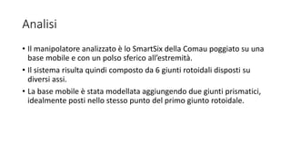
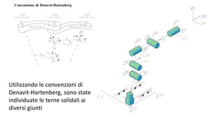
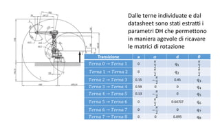
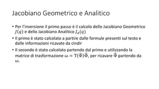
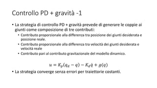
Il documento presenta un progetto su un manipolatore robotico SMARSix della Comau, analizzando la cinematica diretta e differenziale, oltre alla pianificazione della traiettoria e controllo del sistema. Utilizzando MATLAB e l'ambiente di simulazione V-REP, sono stati sviluppati algoritmi per l'inversione cinematica e il controllo delle traiettorie. I risultati delle simulazioni sono stati confrontati con le teorie, confermando la congruenza dei dati con l'implementazione pratica.

![Cinematica Diretta
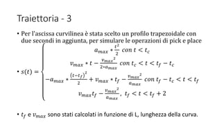
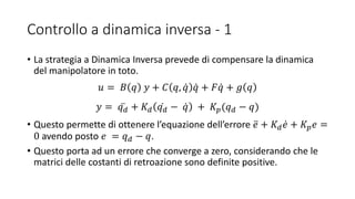
• Il primo passo è stato lo sviluppo di una procedura per il calcolo della
cinematica diretta.
• La procedura prende in ingresso la configurazione dei giunti del
manipolatore, una stringa per la tipologia degli angoli di Eulero e le
matrici 𝐴0
𝑏
e 𝐴 𝑒
𝑛
di relazione con la terna mondo e quella end effector
• In uscita restuisce la posizione dell’end effector, l’orientamento
secondo gli angoli scelti, la matrice di rotazione 𝑅 𝑒
𝑏 e un cell array con
tutte le matrici intermedie calcolate.
function [p, phi, R, A] = cindir(q, str, Ab0, Ane)](https://image.slidesharecdn.com/presentazionerobotica-160917172505/85/Robotic-Arm-Simulation-7-320.jpg)
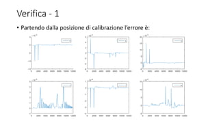
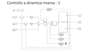
![Procedura DHMatrix
• Per aiuto nello sviluppo, è stava sviluppata una procedura che dati i
parametri DH calcola la matrice di rototraslazione corrispondente.
• La stessa poi è stata utilizzata più volte per calcolare 𝐴 𝑒
𝑏, da cui sono
stati ricavate tutte le altre informazioni ritornate da cindir.
function [A] = DHMatrix(a, alpha, d, theta)](https://image.slidesharecdn.com/presentazionerobotica-160917172505/85/Robotic-Arm-Simulation-8-320.jpg)
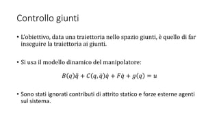
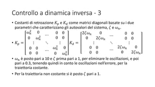
![Verifica
• Confronto dei risultati in uscita dalla procedura realizzata con quelli
simulati dall’ambiente V-REP.
• In primo luogo sono stati verificati i risultati in posizione di
calibrazione, ovvero [0,0,0,−
𝜋
2
,0,0,0,0]T e i valori sono congruenti.
• Un’ulteriore prova è stata fatta in una posizione casuale
[5,5,0,0,−
𝜋
2
,0,0,0]T e si è notata una discrepanza di 0.06 mm nella
coordinata z della posizione causata dai limiti fisici dei giunti, nel caso
particolare dal giunto 5.
• Questo problema è stato risolto utilizzando il file
LimitiManipolatore.m](https://image.slidesharecdn.com/presentazionerobotica-160917172505/85/Robotic-Arm-Simulation-9-320.jpg)
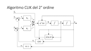
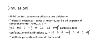
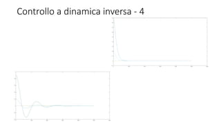
![Inversione Cinematica
• Secondo passo è stato il calcolo della cinematica differenziale ai fini
dell’inversione cinematica, implementata attraverso un algoritmo CLIK
del secondo ordine
• La funzione prende in ingresso una configurazione iniziale, una
traiettoria in posizione, velocità e accelerazione, oltre che
informazioni su eventuali ostacoli.
function [q, dq, ddq, e] =
InversioneCinematica(q0, xd, dxd, ddxd, str, Ab0, Ane, obs)](https://image.slidesharecdn.com/presentazionerobotica-160917172505/85/Robotic-Arm-Simulation-10-320.jpg)
![Verifica - 2
• Partendo dalla posizione 𝑞1 = [0.5; 0.5; 0; −
𝑝𝑖
2
; 0 ; 0.1; 1.2; 0.9]
l’errore è:](https://image.slidesharecdn.com/presentazionerobotica-160917172505/85/Robotic-Arm-Simulation-18-320.jpg)


![La retta[1]](https://cdn.slidesharecdn.com/ss_thumbnails/laretta1-140930151800-phpapp01-thumbnail.jpg?width=640&height=640&fit=bounds)