Download as PDF, PPTX
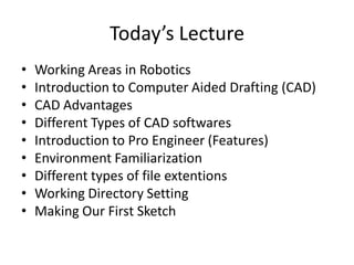
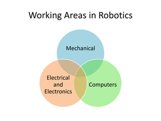
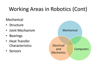
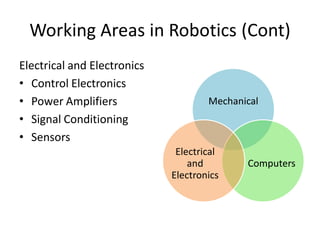
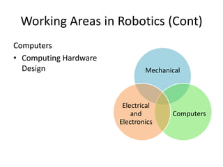
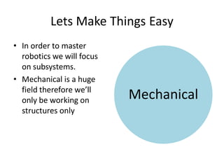
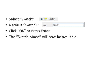
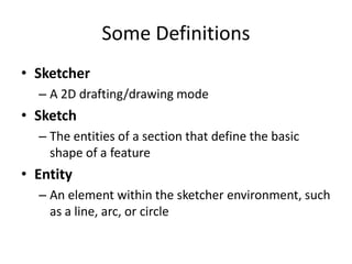
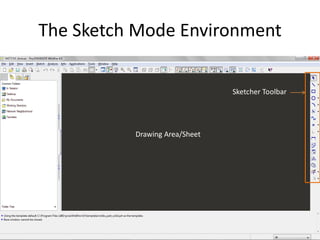
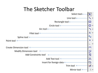

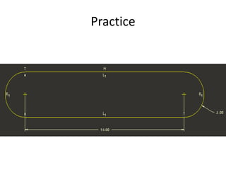

The document outlines the agenda for a robotics workshop, including an introduction to computer aided drafting software and the ProEngineer CAD program. It discusses the different working areas in robotics such as mechanical, electrical, electronics, and computers. The workshop will also cover the basics of sketching and drawing entities in CAD, including lines, rectangles, circles, and arcs.


