Download to read offline


This document discusses types of rigid pavement distresses, including cracking, joint distresses, and disintegration. It describes different types of cracks such as longitudinal, transverse, diagonal, D-cracking, and corner breaks. It also discusses joint seal damage, joint load transfer system deterioration, and disintegration issues like scaling, map cracking, crazing, spalling, blowups, shattered slabs, punchouts, and popouts. For each distress, it provides descriptions, possible causes, examples, and rehabilitation methods.
Overview of the presentation focusing on rigid pavements distresses by Ahmed Fahim Rahi under Prof. Saad Sarsam.
Introduction to six types of distresses: cracking, joints, disintegration, distortion, and other distresses.
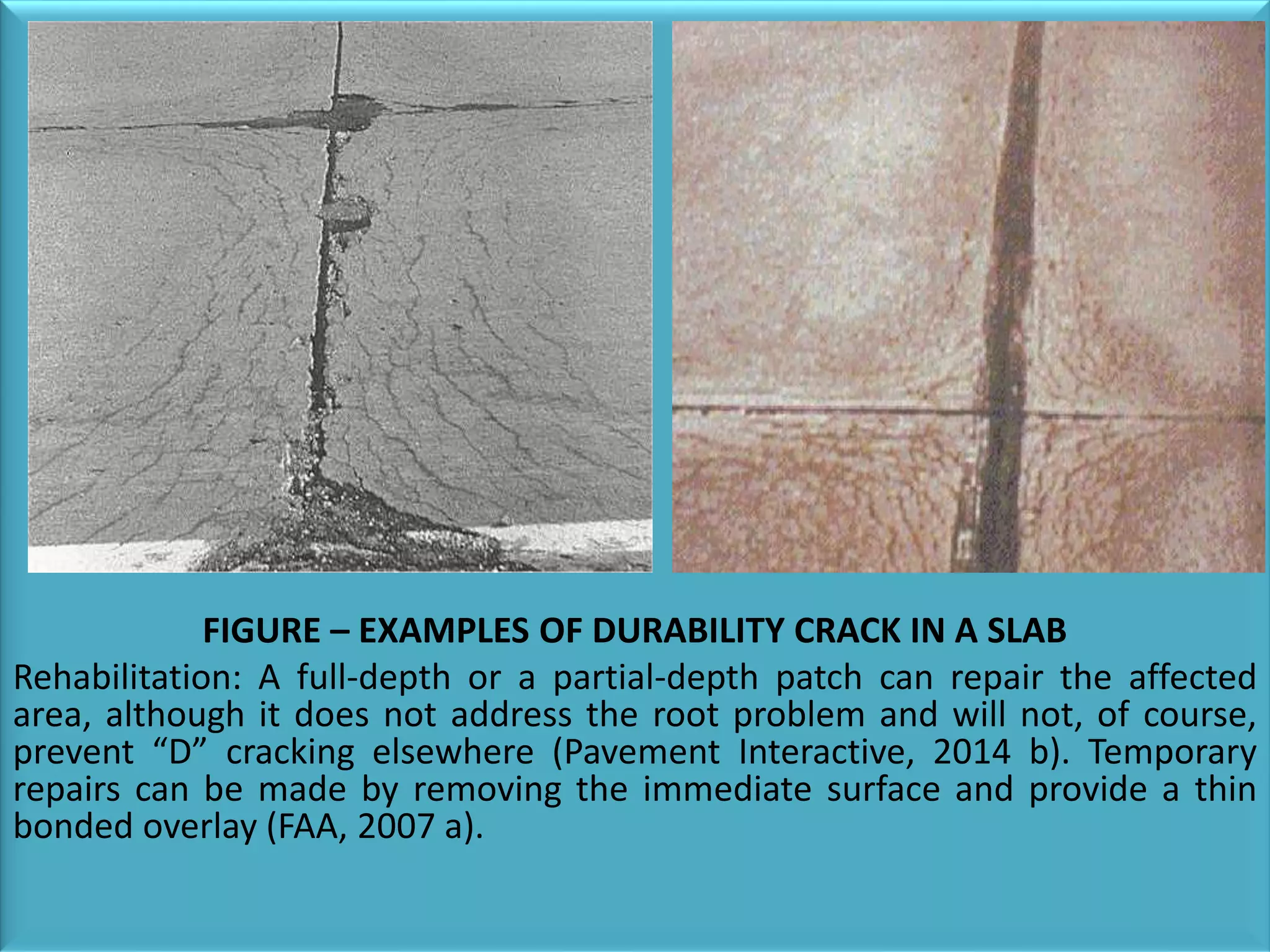
Discusses various crack types: longitudinal, durability, corner breaks, and shrinkage cracking with causes and repair methods.
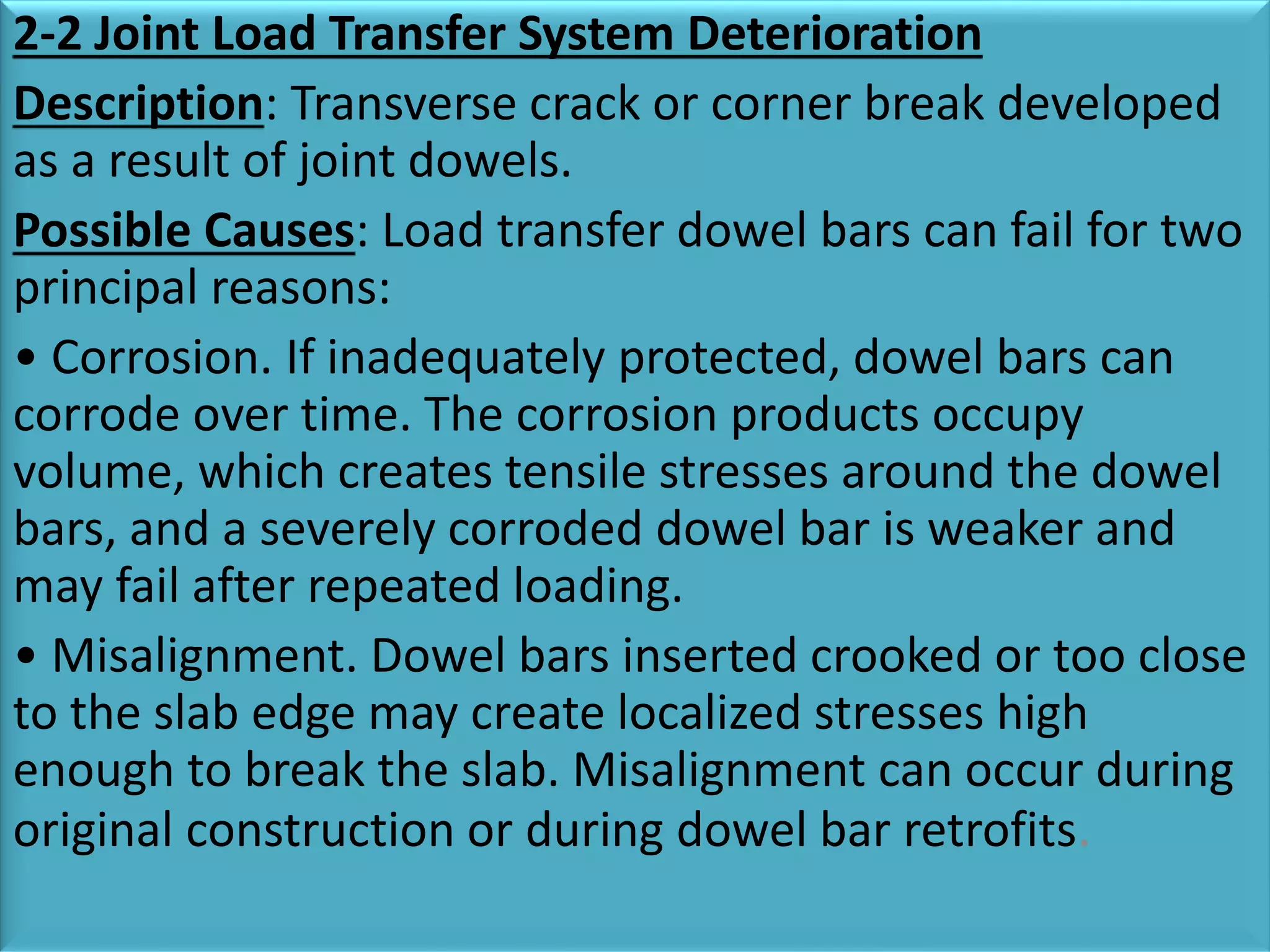
Details on joint seal damage and joint load transfer system deterioration, including causes and rehabilitation techniques.
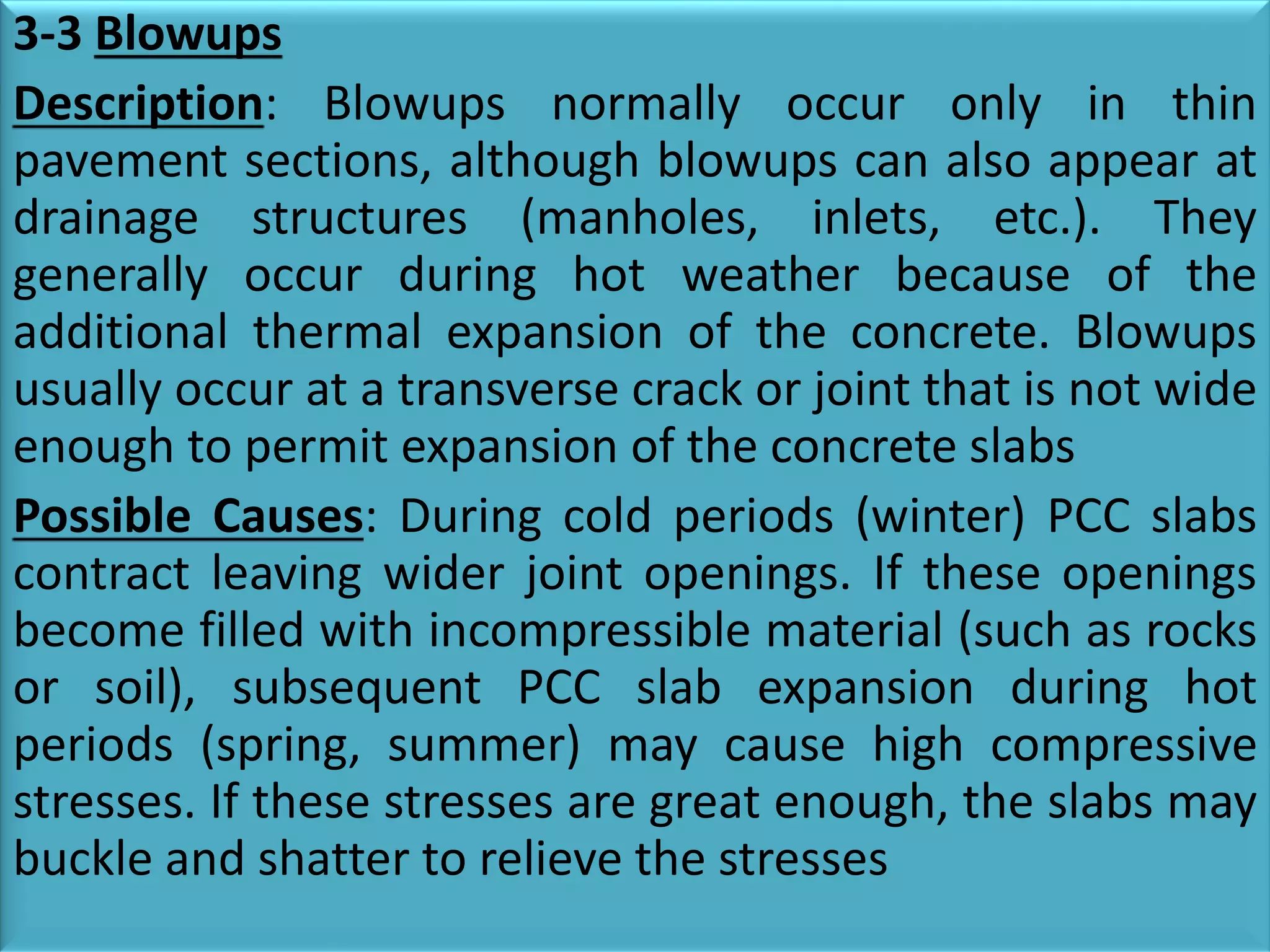
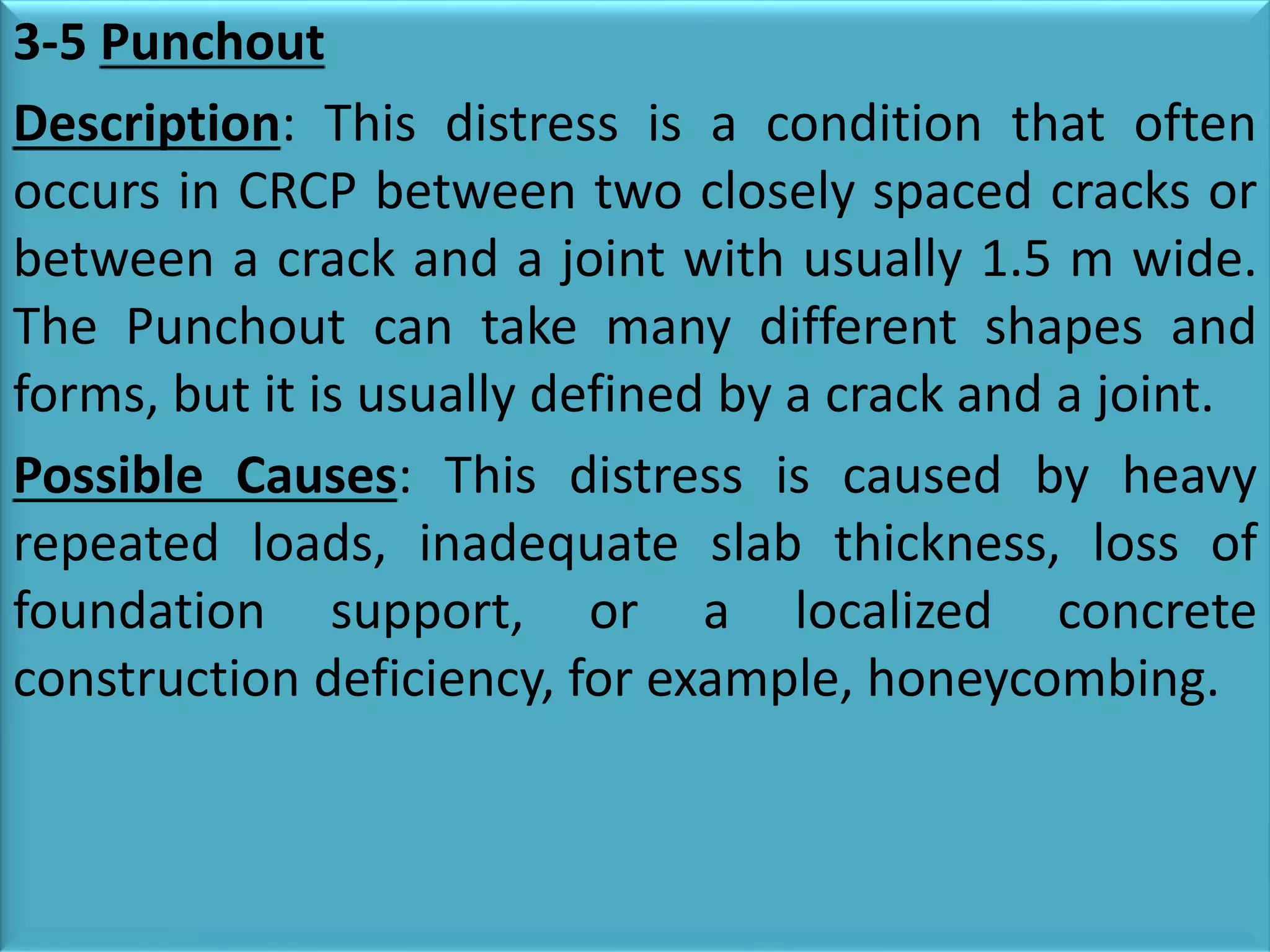
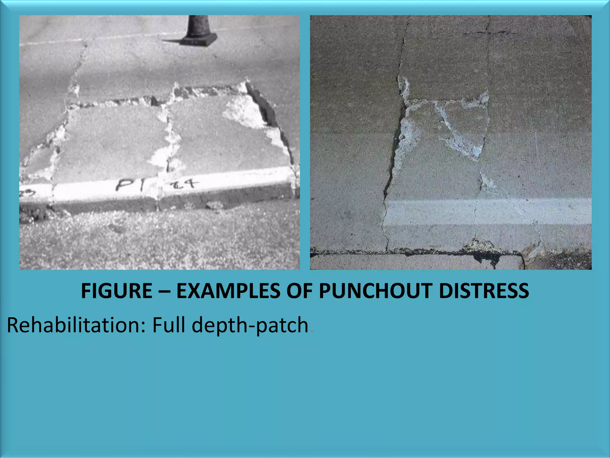
Explains disintegration and various forms including scaling, spalling, blowups, shattered slabs, and popouts with rehabilitation methods.
Covers distortion types: pumping and settlement/faulting, their causes, and impacts on pavement structure.
Mentions other types of distresses including polished aggregates and lane/shoulder dropoff.
Final slide summarizing the end of the presentation on rigid pavement distresses.