Download as PDF, PPTX
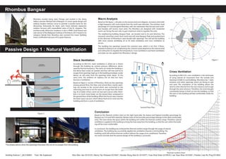
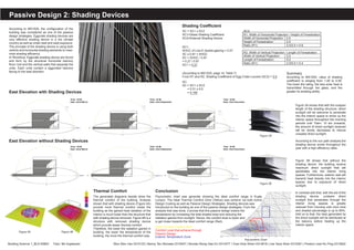

The document discusses the passive design strategies used in Rhombus, a residential building in Bangsar, Malaysia. Natural ventilation strategies like cross ventilation and stack ventilation were used to regulate temperature without air conditioning. The building's orientation and openings allow winds to flow through. Shading devices were also implemented, like eggcrate louvers on balconies, to reduce solar heat gain and improve thermal comfort inside. Analysis showed the passive designs helped bring the interior humidity and temperature within comfortable ranges without active cooling systems.


