The document outlines the use of Revit MEP for designing electrical systems, including lighting, power, and communications. It details the creation and management of circuits, switch systems, electrical sizing, and calculations, as well as the selection of fixtures and coordination with other model elements. Additionally, it emphasizes the importance of understanding electrical design requirements and features resources for further learning.
![Further reading
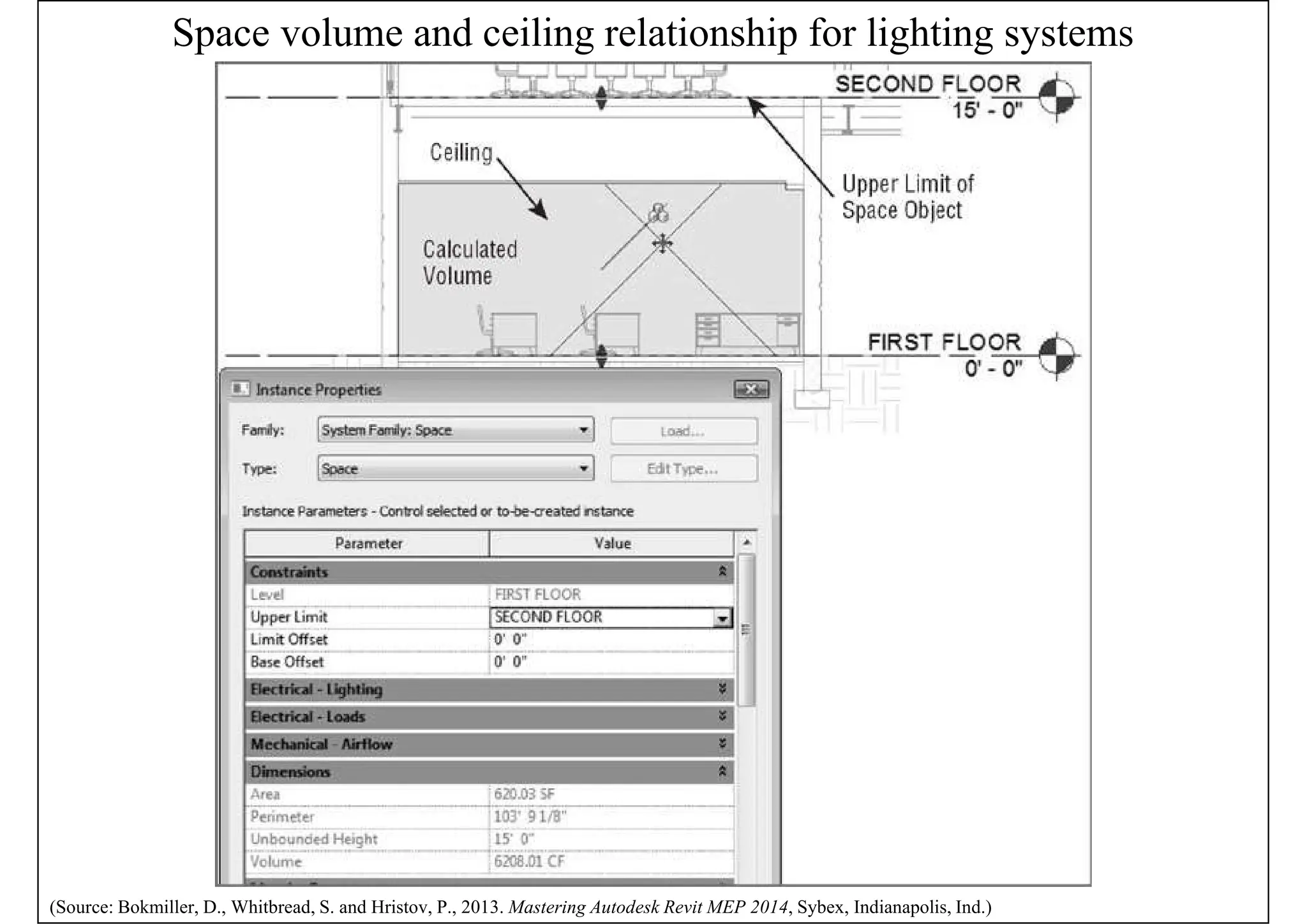
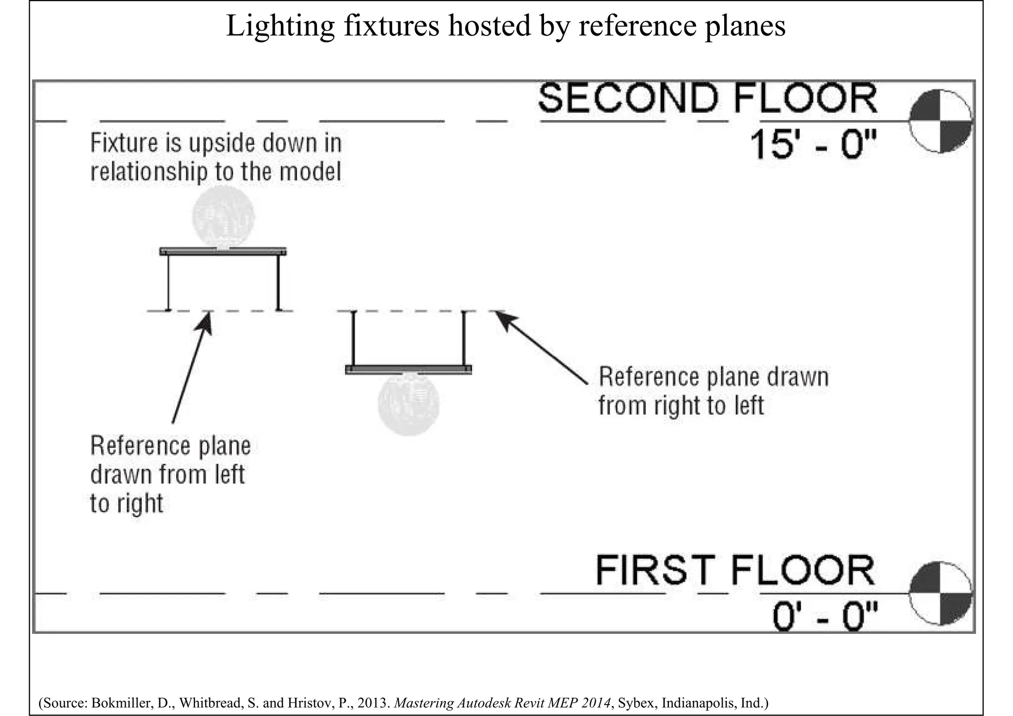
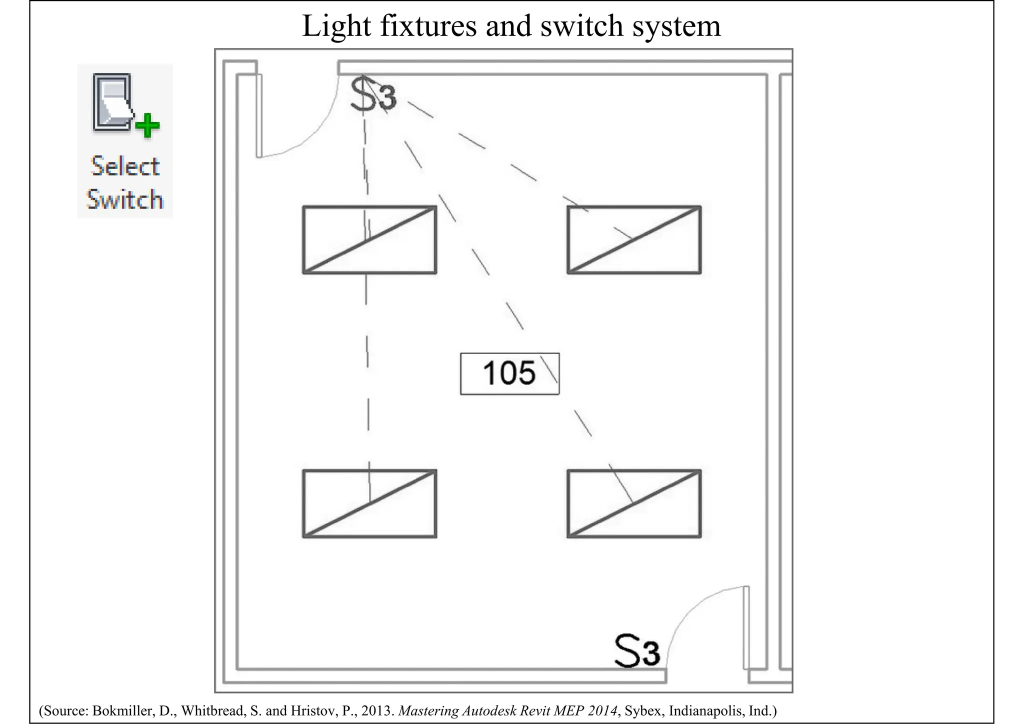
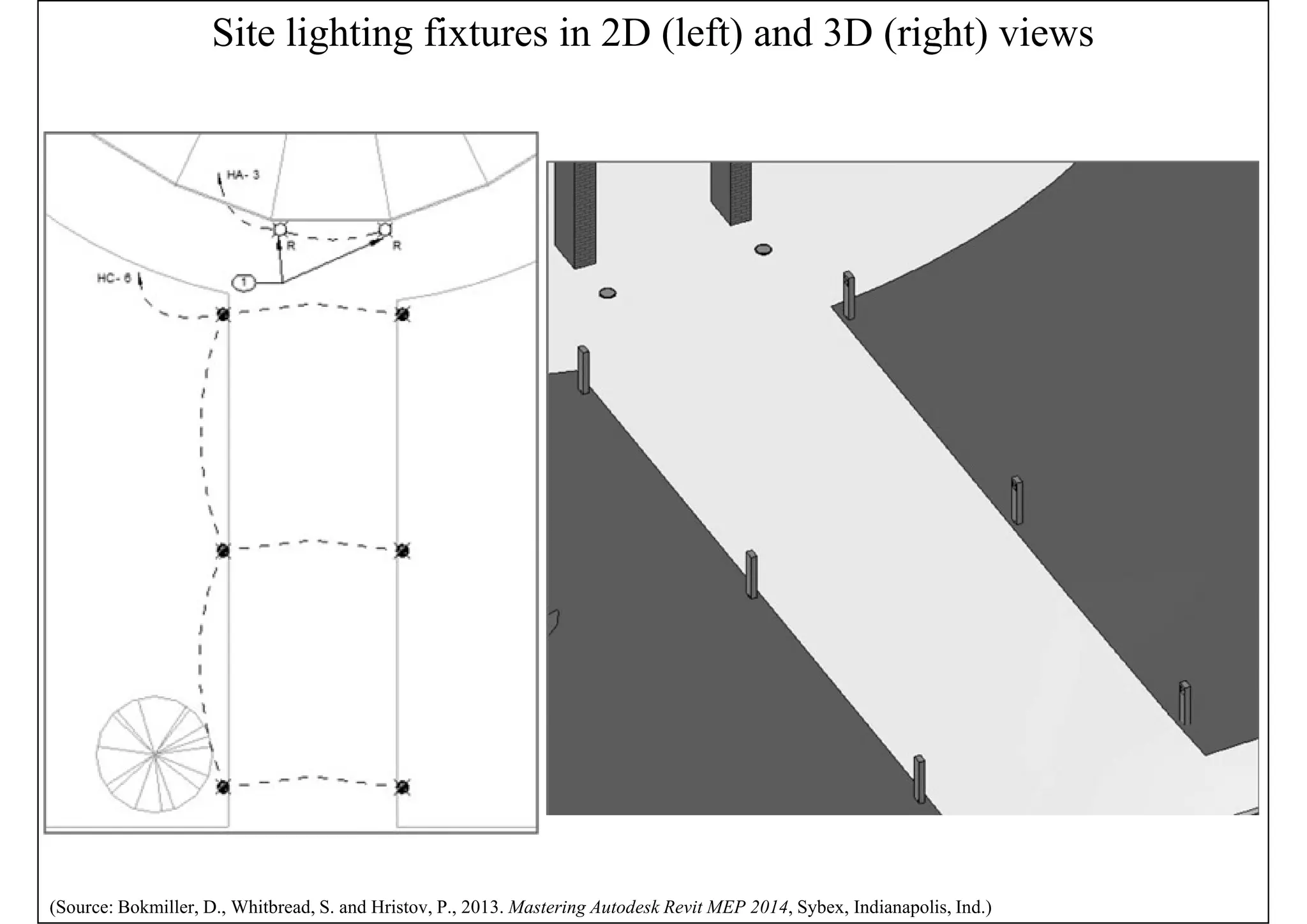
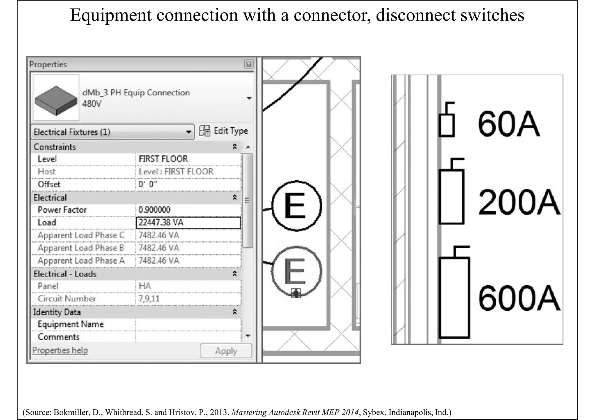
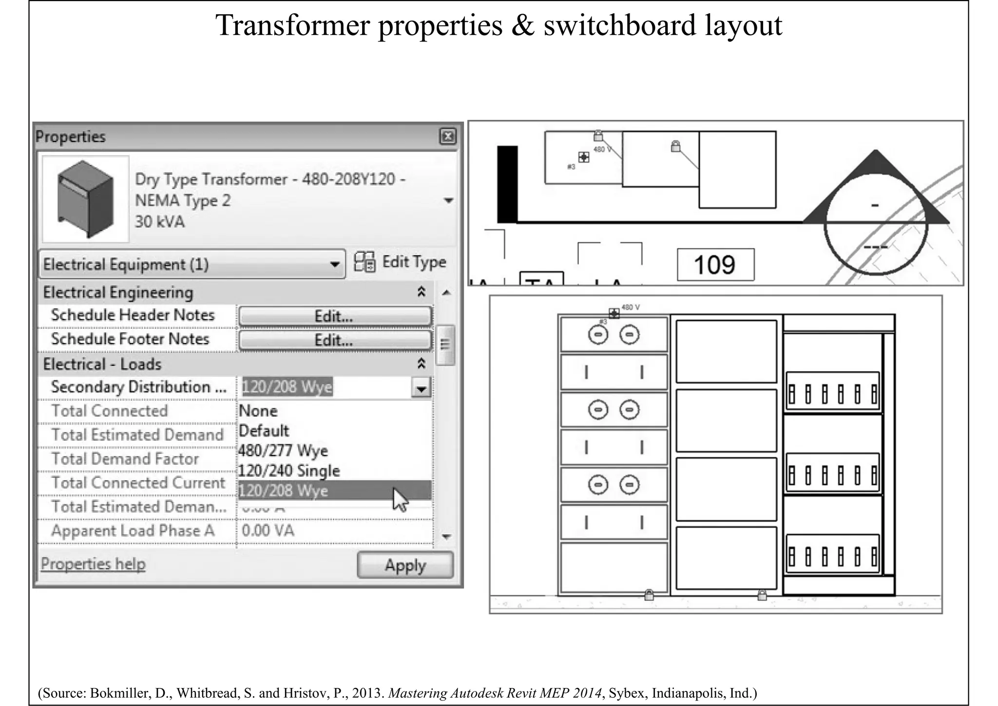
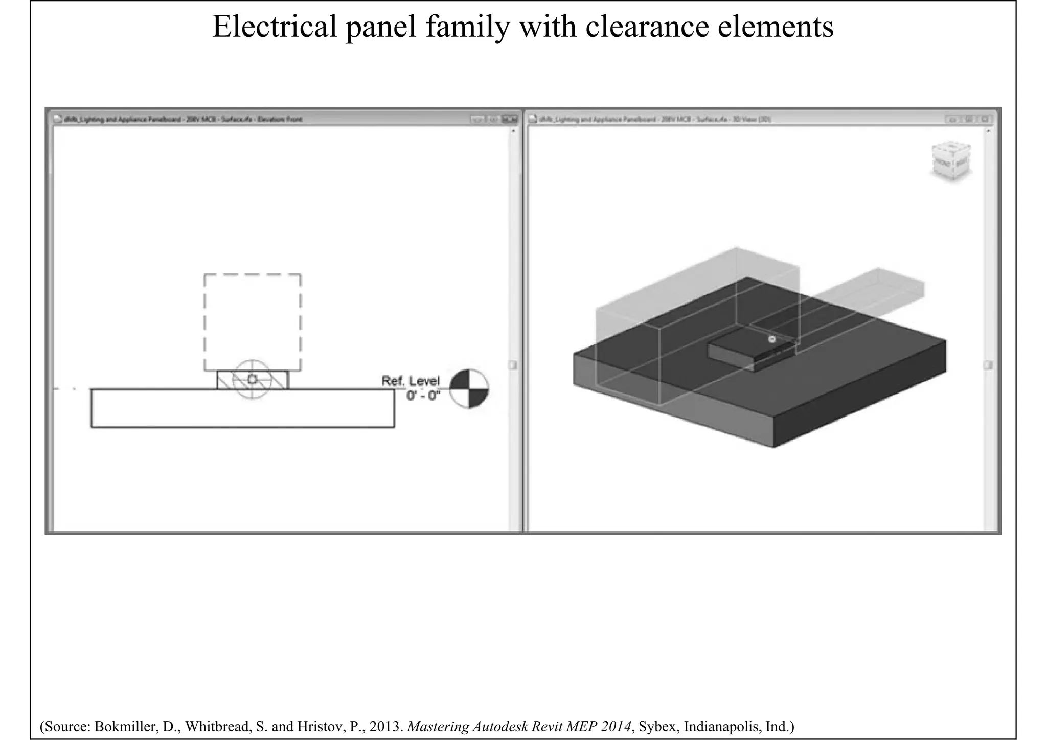
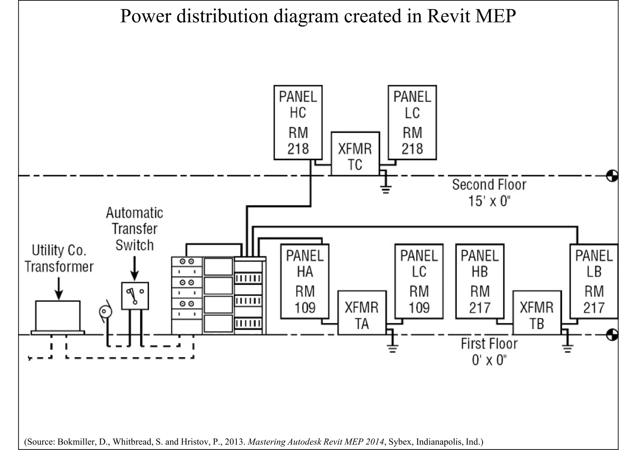
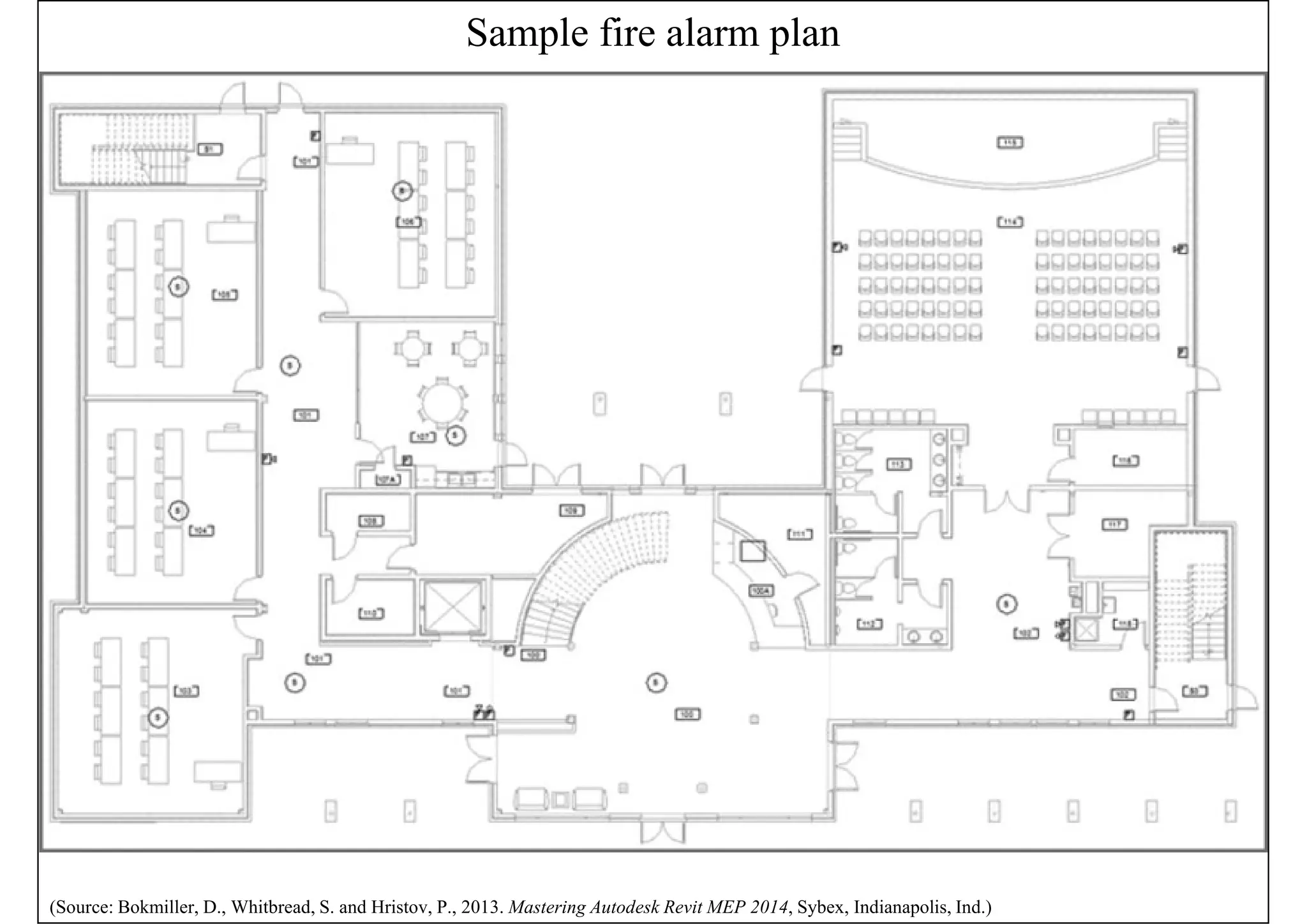
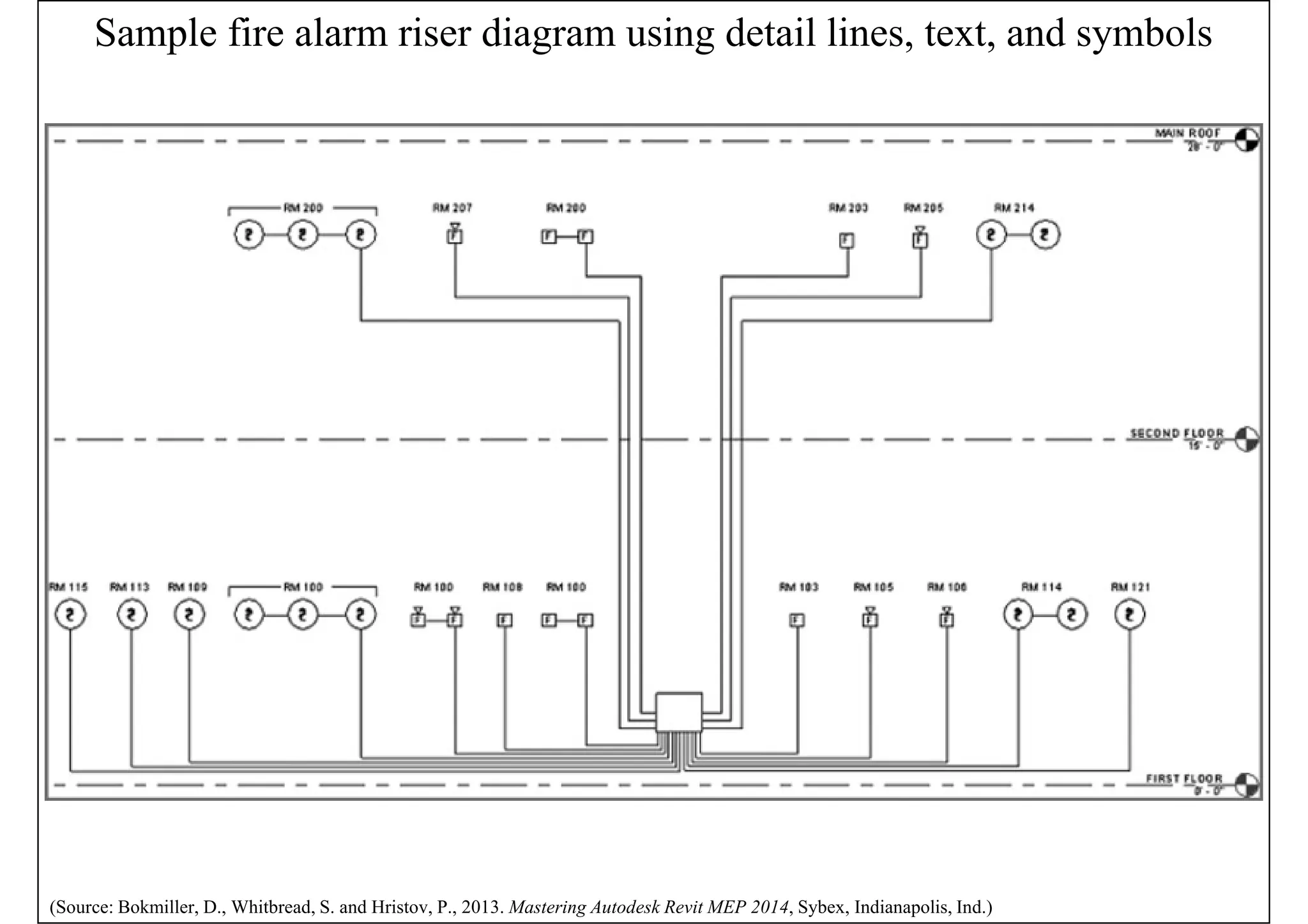
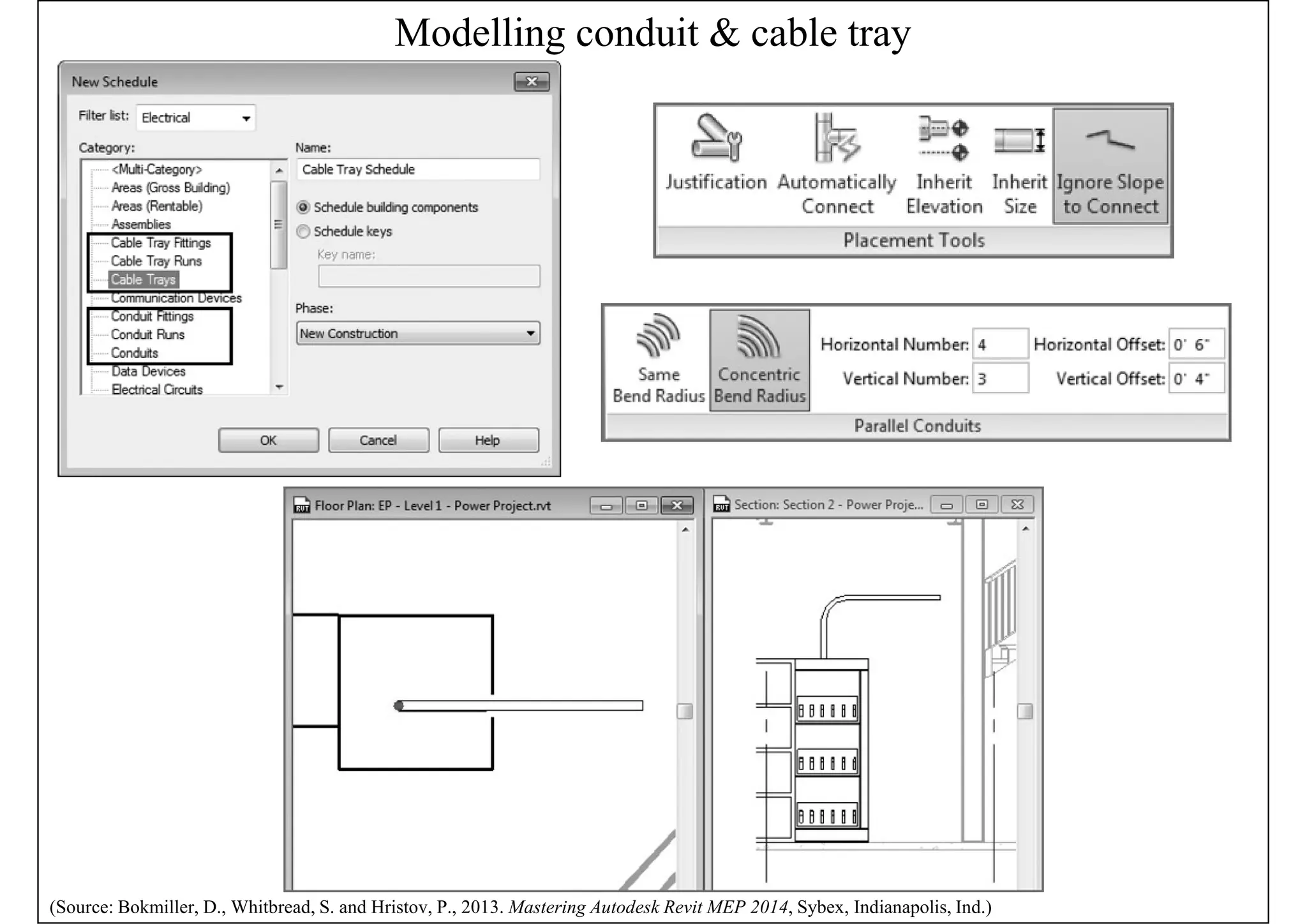
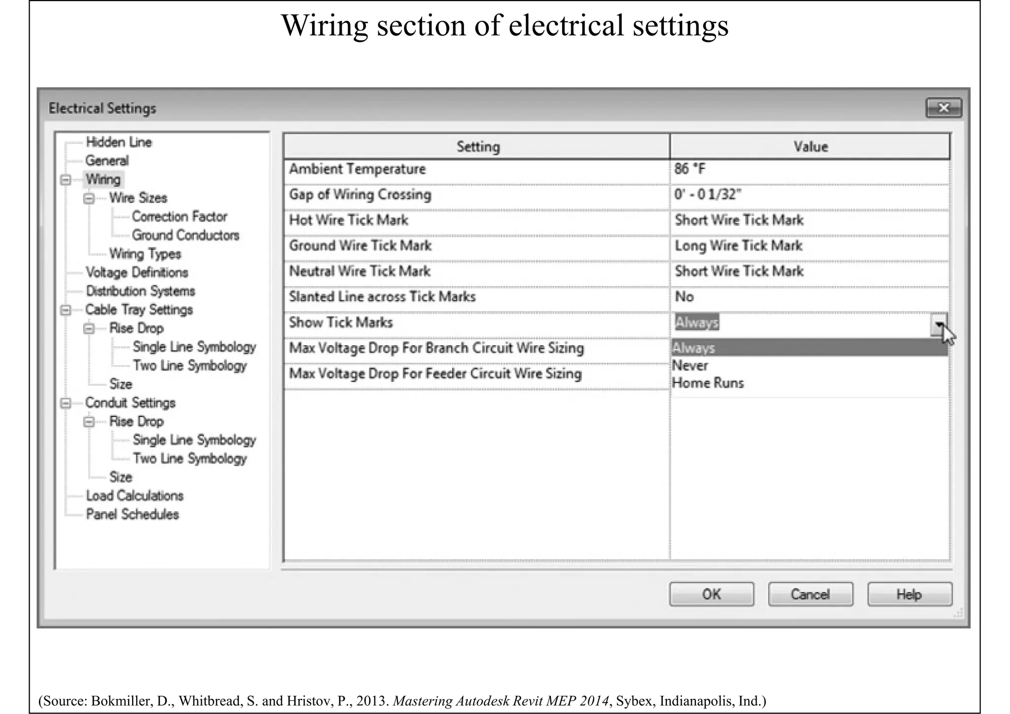
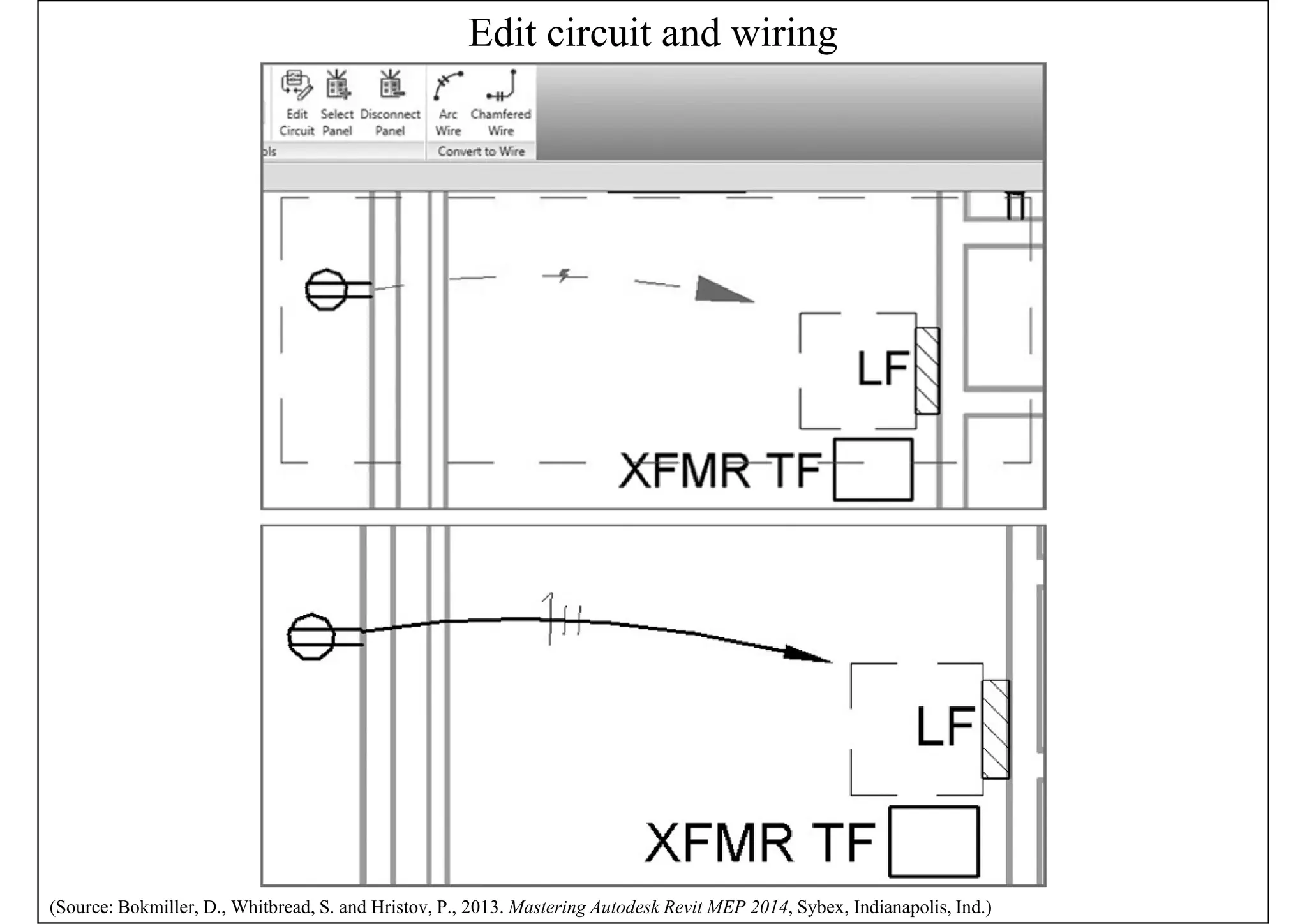
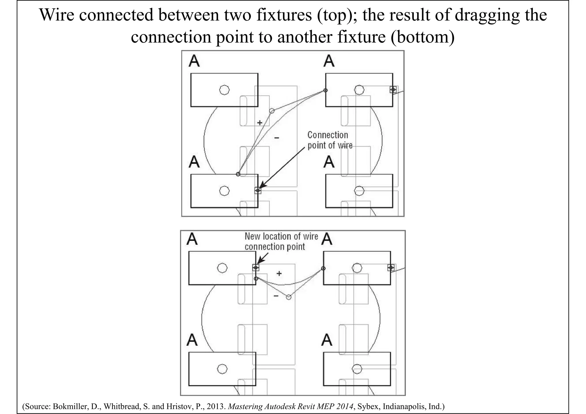
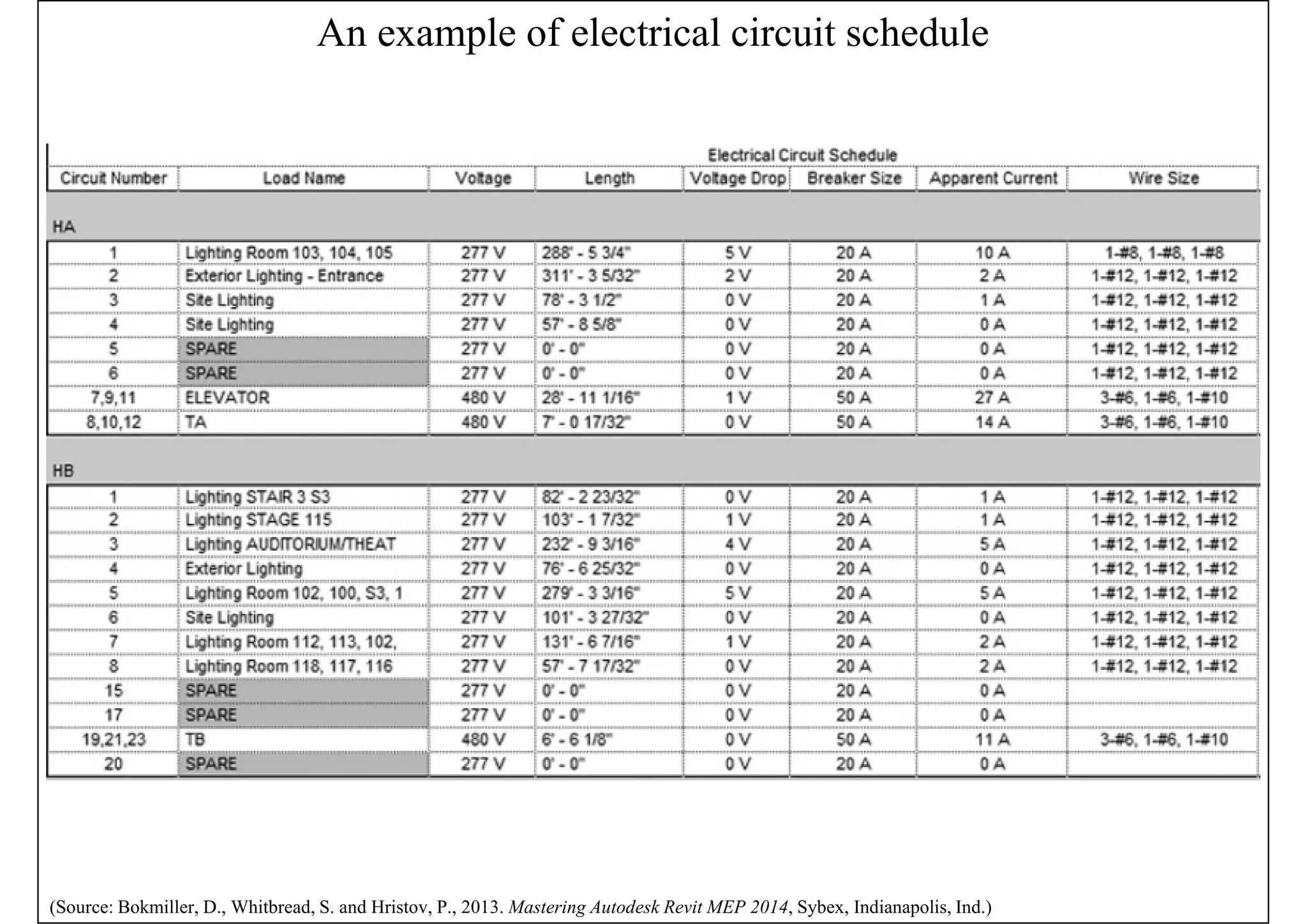
• Bokmiller, D., Whitbread, S. and Hristov, P., 2013. Mastering
Autodesk Revit MEP 2014, Sybex, Indianapolis, Ind. [TH 6010
.B65 2013 (ebook)]
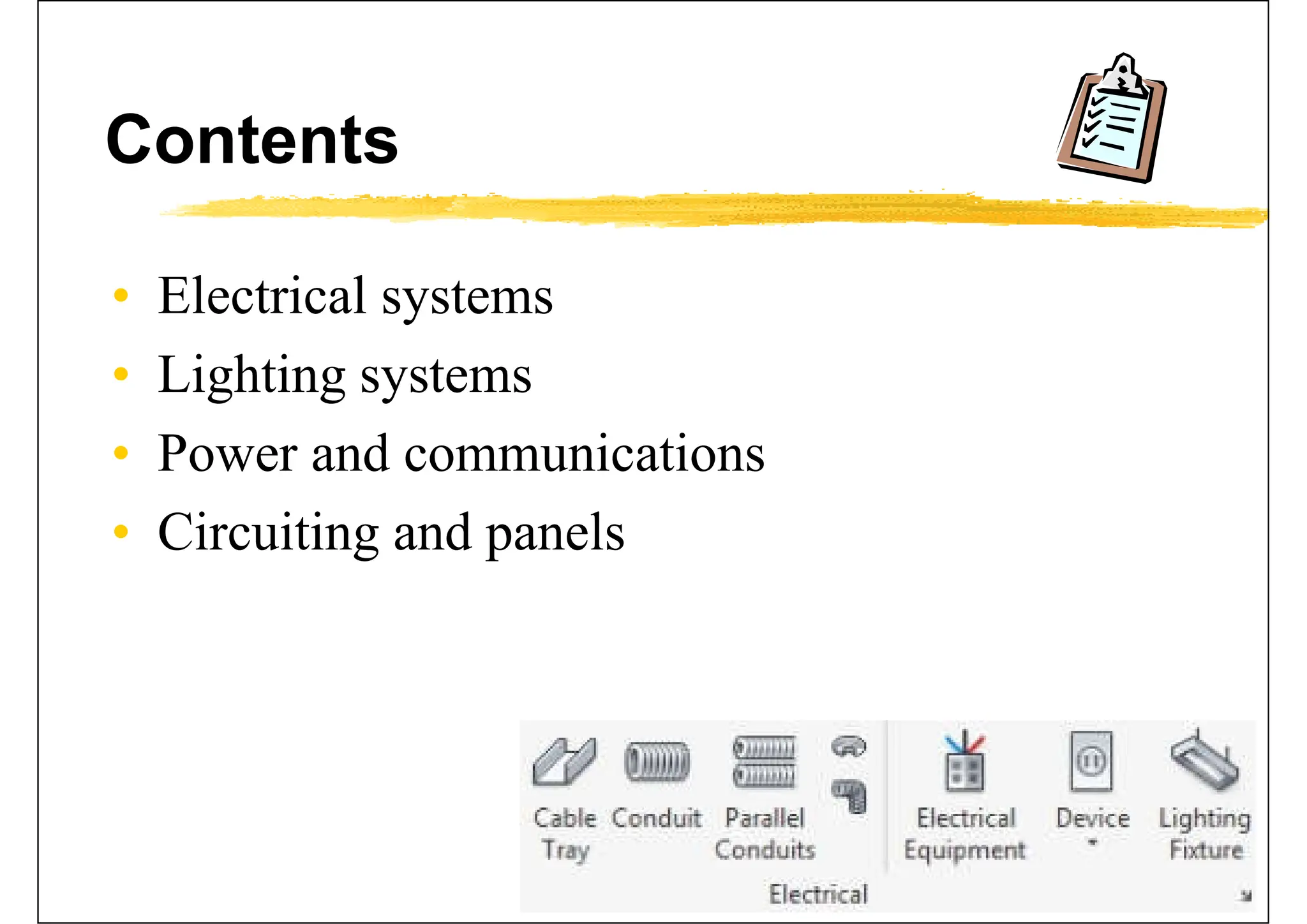
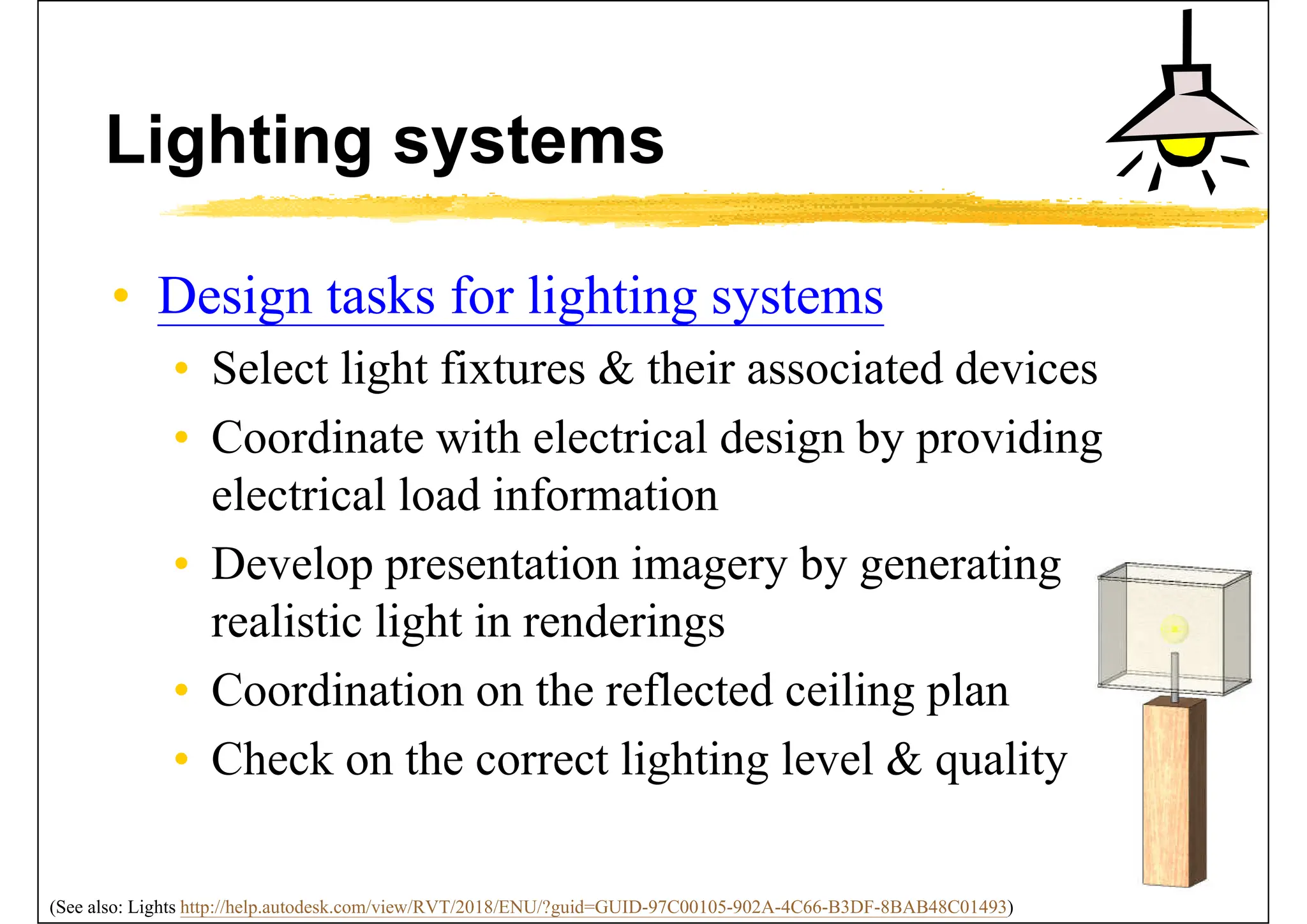
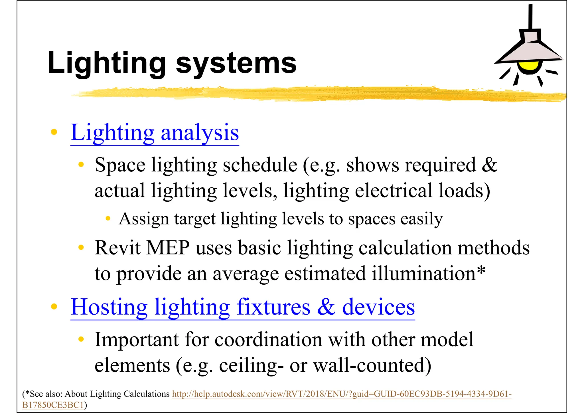
• Chapter 12 - Lighting
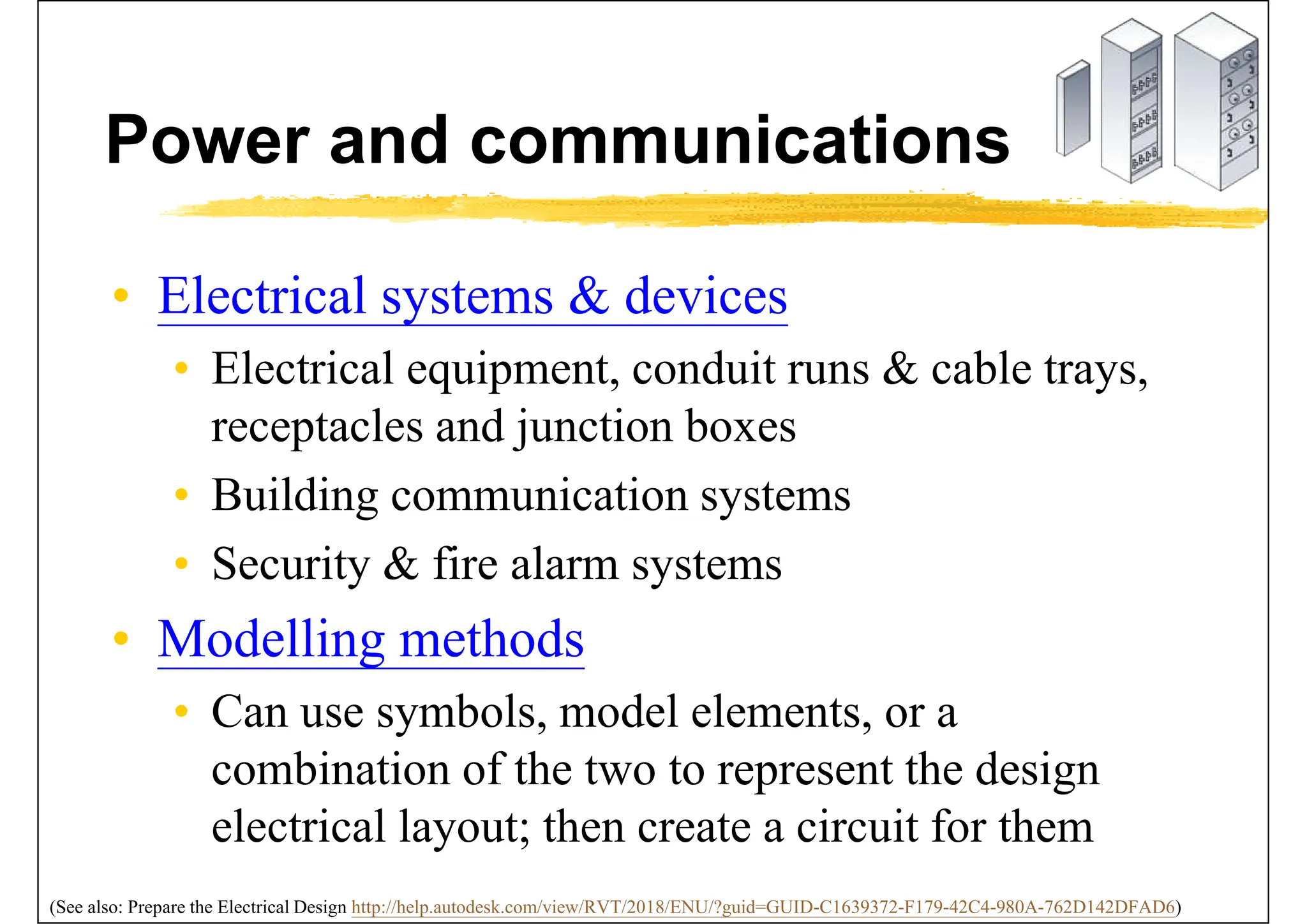
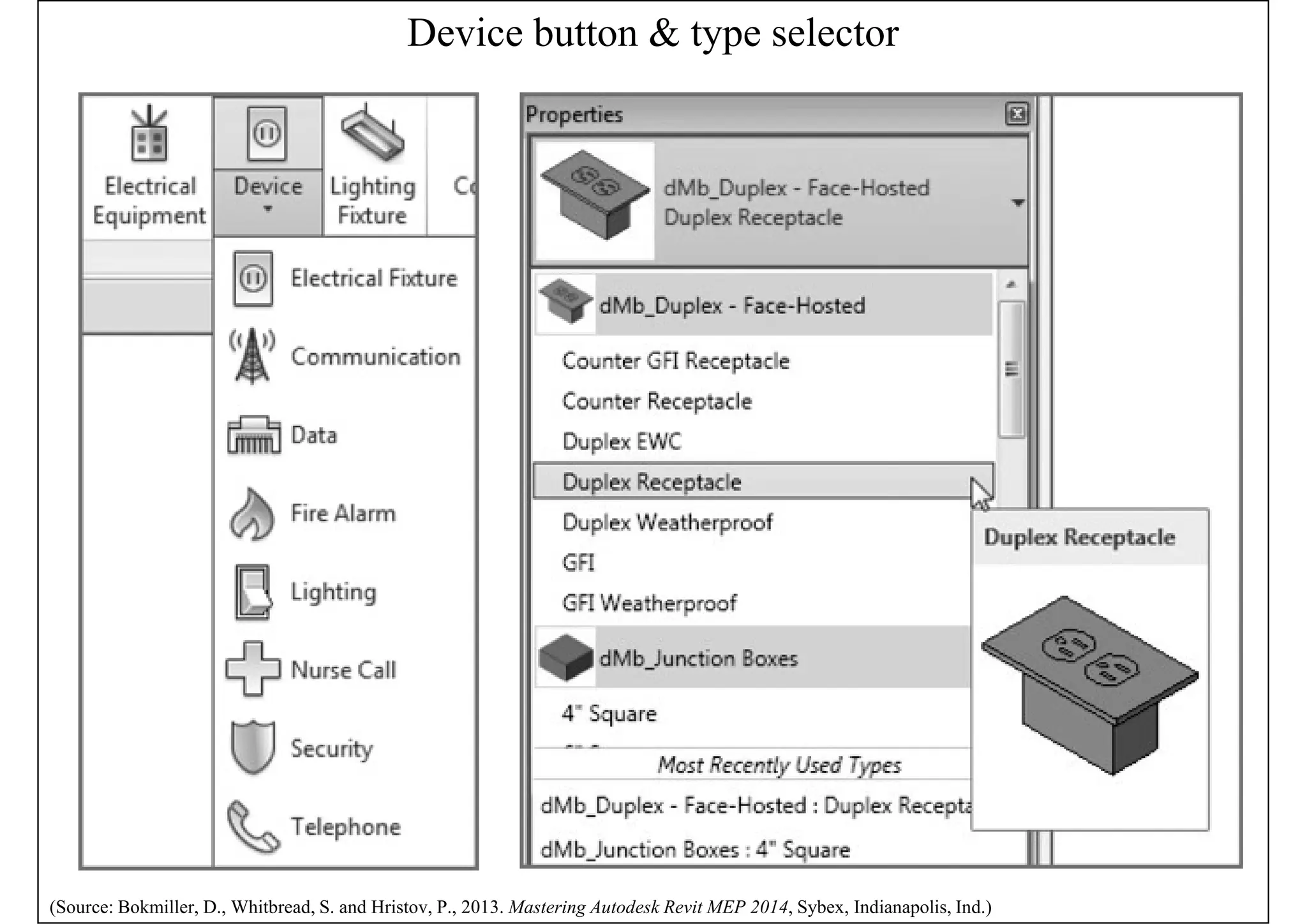
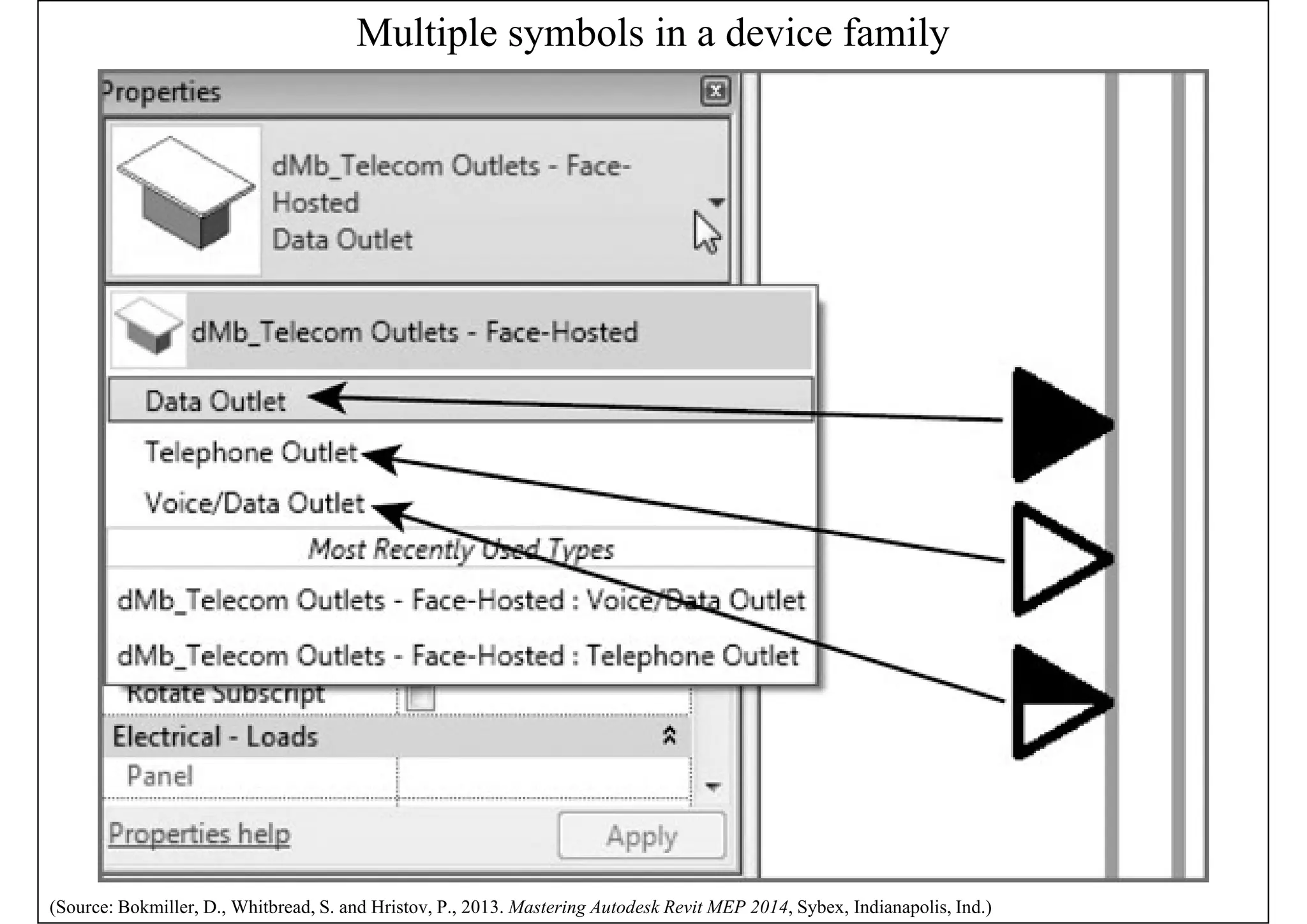
• Chapter 13 - Power and Communications
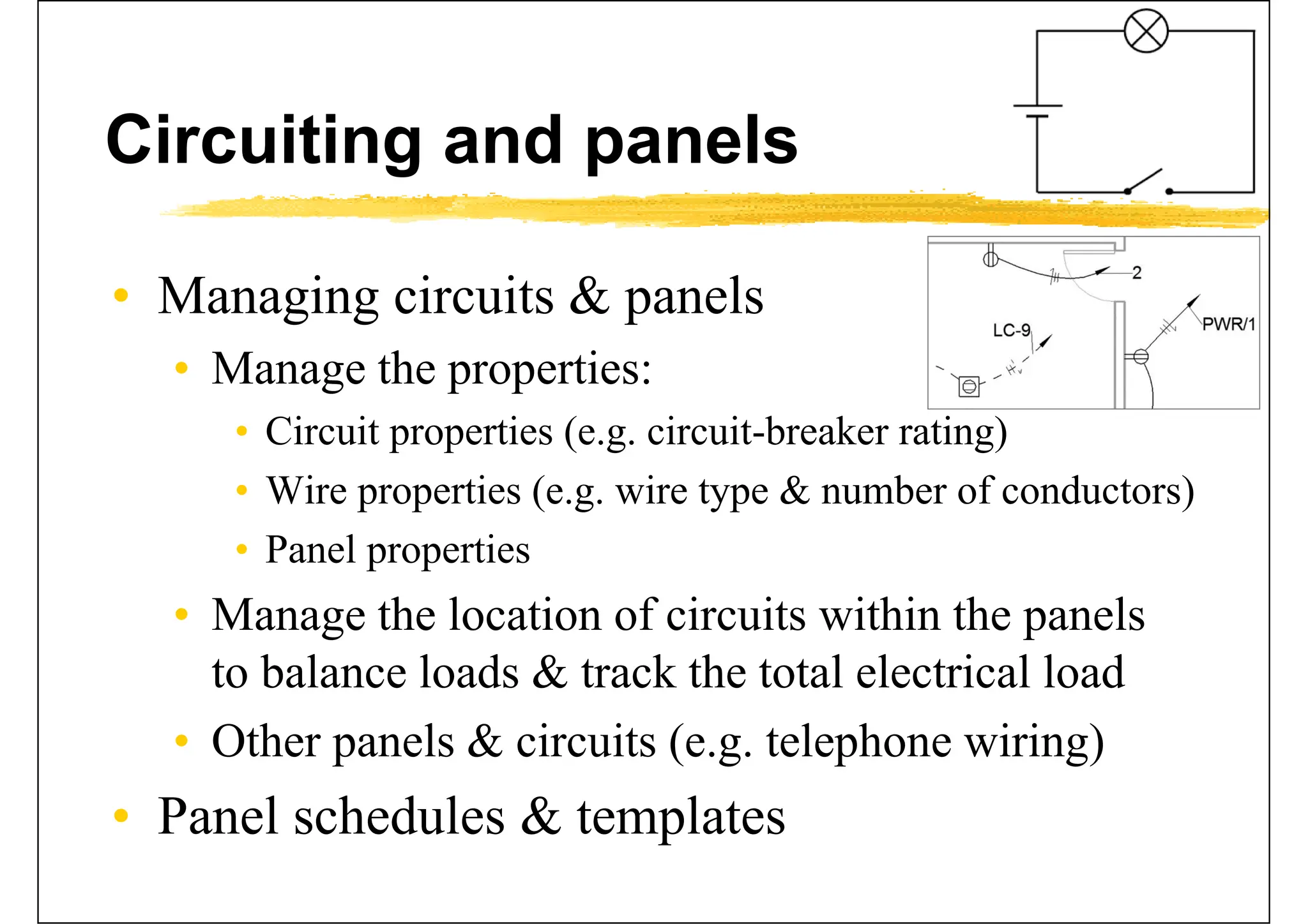
• Chapter 14 - Circuiting and Panels
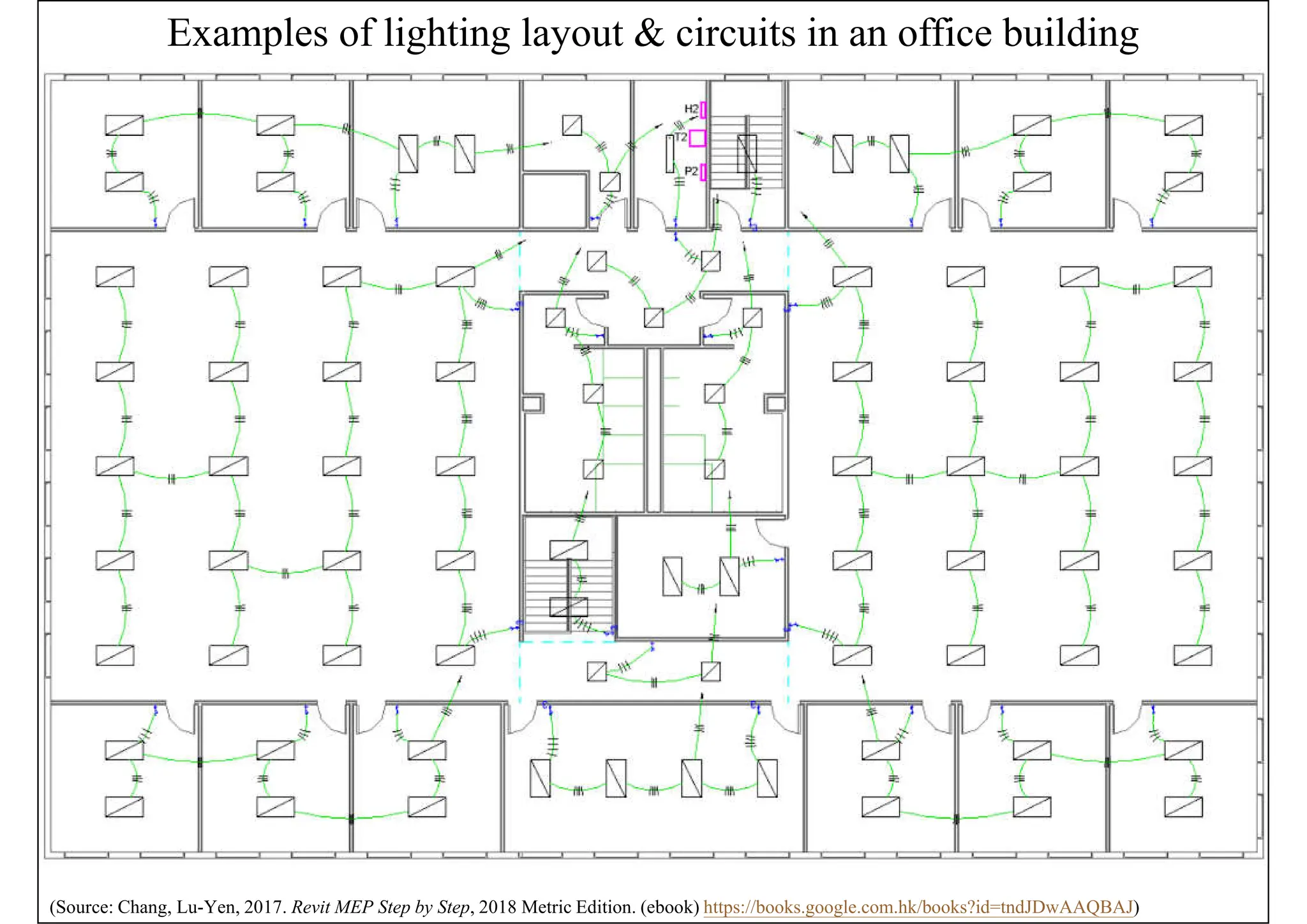
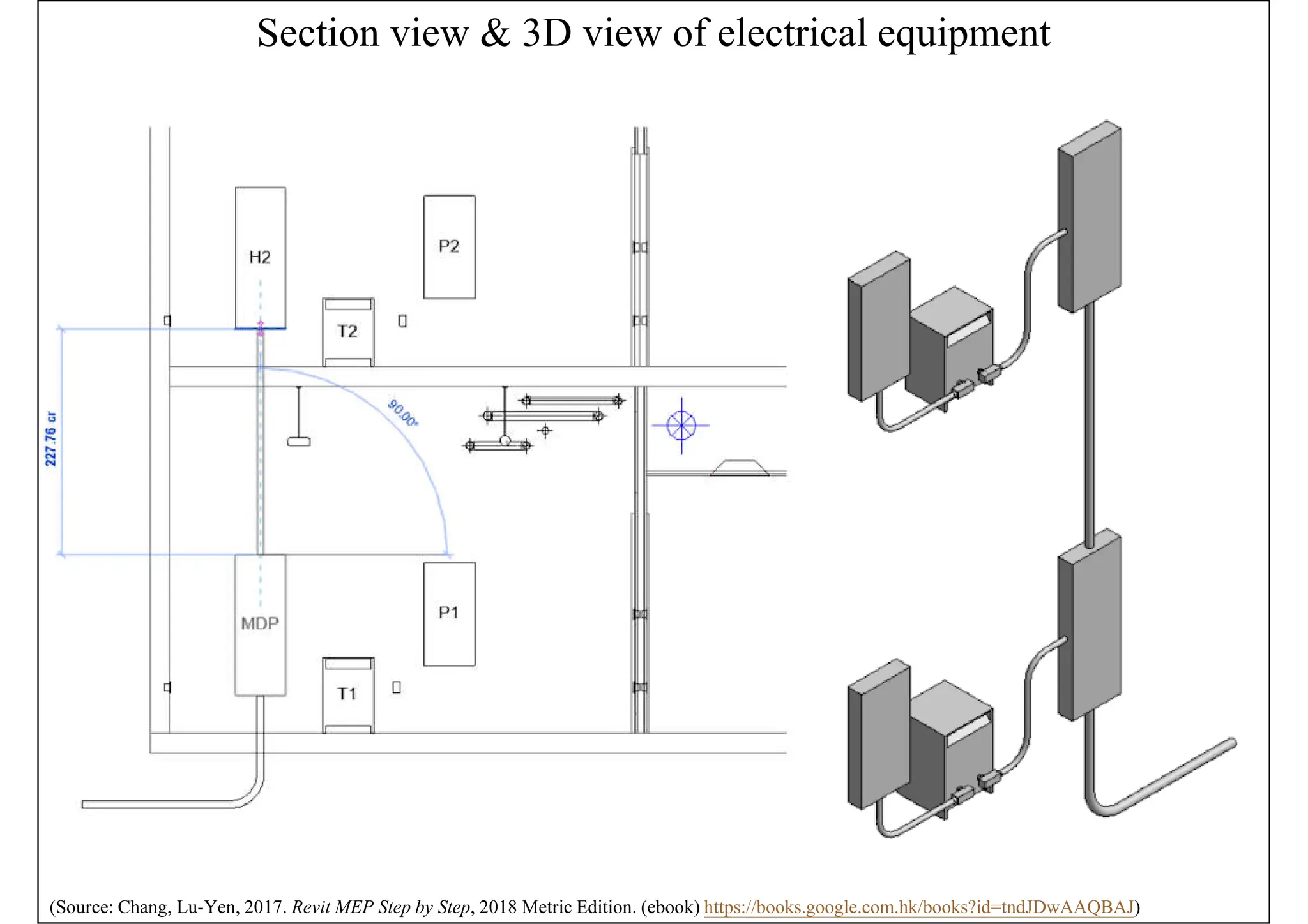
• Chang, Lu-Yen, 2017. Revit MEP Step by Step, 2018 Metric
Edition. (ebook) https://books.google.com.hk/books?id=tndJDwAAQBAJ
• Chapter 4 Electrical Systems
• Videos: Electrical Engineering
• http://help.autodesk.com/view/RVT/2018/ENU/?guid=GUID-
3C209C9A-51FA-4F9A-8445-D493134DD444
• Watch these videos to learn how to work with electrical engineering tools to build systems.](https://image.slidesharecdn.com/revitelectricalmaterial-250128180728-a1b04a92/75/Revit-MEP-Electrical-Material-for-beginners-42-2048.jpg)