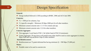
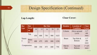
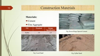
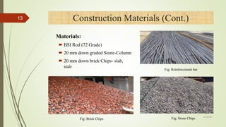
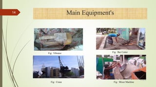
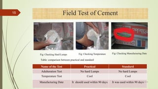
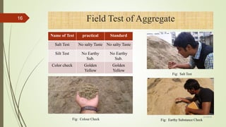
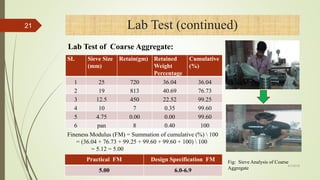
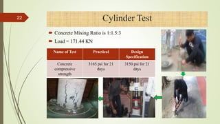
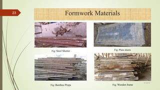
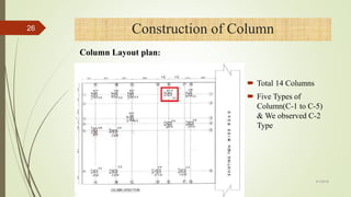
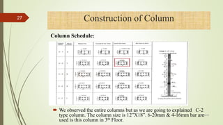
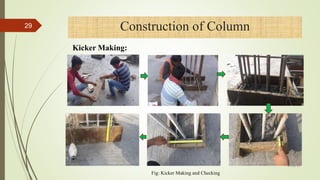
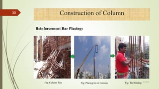
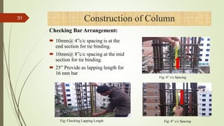
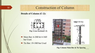
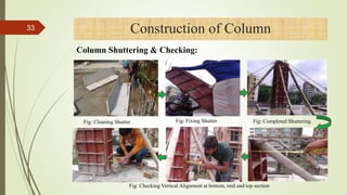
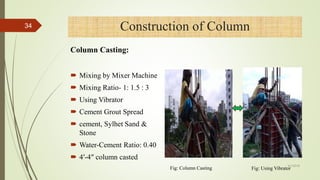
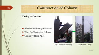
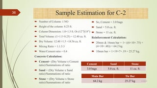
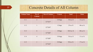
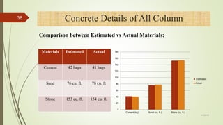
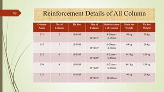
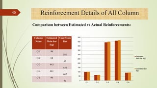
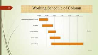
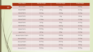
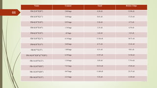
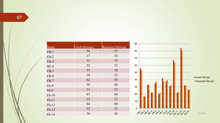
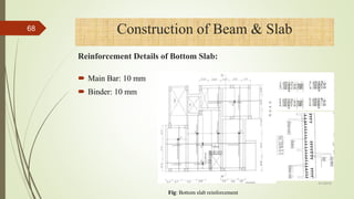
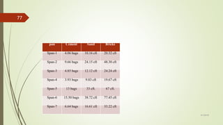
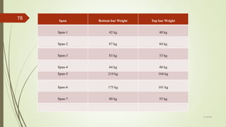
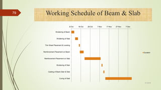
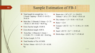
The document summarizes the construction process of columns for a seven storied residential building. It describes the process of forming kickers, placing reinforcement bars, shuttering, casting, and curing concrete columns. It provides details on the types and sizes of columns constructed, reinforcement details, and estimates of required construction materials. Laboratory and field tests were conducted to ensure quality of materials and construction methods.
1. Study on the Construction Process of
Superstructure of a Seven Storied Residential
Building
Presented By-
Md. Mahfuzur Rahman Jony Md. Khokan Mia
Id# 14106020 Id# 14106028
Program: BSCE Program: BSCE
IUBAT – International University of Business Agriculture and Technology
1
4/1/2018
2. CONTENTS
Introduction
Objectives
Company overview
Company organogram and our project details
Design specification
Construction materials & equipment's
Construction process of beam, slab, stair & column
Problems & solution
Recommendation
Conclusion
2
4/1/2018
3. INTRODUCTION
In this presentation we will try to present our 4 month’s practicum
experience of the construction work of a seven storied residential building.
We observed the construction process of super structural parts of a
reinforced concrete building.
Here we have focused on mainly column, stair, beam and slab construction
process.
3
4/1/2018
4. OBJECTIVES
To get knowledge about the structural drawing & design specification.
To implement the structural drawing into construction site.
To understand the construction and supervision work of column, stair,
beam and slab.
To learn about the estimating details of Super Structural work.
To acquire knowledge about the steps involving construction process.
To learn how to solve the rising problems and unexpected events.
4
4/1/2018
5. Company Overview
Company Name: Tokyo Development Engineer’s Ltd.
Office Address: House- 26, Road- 09, Sector-13,
Uttara, Dhaka- 1230
Phone: 02-550 89047, 550 88865
E-mail: tokyobd@yahoo.com
Web: www.tokyobd.com
5
4/1/2018
10. General:
Design method followed is USD according to BNBC, 2006 and ACI Code 2008.
Concrete:
f’c = 3500 psi for columns, Cap
f’c (specific strength) = Minimum 20 Mpa (3000 psi) for all other members.
Minimum cement concrete ratio 1:1.5:3 for column and cap.
Minimum cement concrete ratio 1:2:4 for other members.
Concrete Aggregate:
Fine aggregate: Local Sand of FM 1.2 & Sylhet Sand of FM 2.0 (minimum)
Coarse Aggregate: 20 mm down well graded stone chips shall be used as coarse aggregate in column,
Shear Wall and Cap and Brick Chips in other members.
Steel Reinforcement:
Reinforcement are 72 grade deformed bar having minimum fy = 500 Mpa (72,000 psi)
Water:
Portable water to be used in concrete mix
Design Specification10
4/1/2018
11. Design Specification (Continued)
Lap Length:
Bar
type
Bar
Positi
on
Bar Size
10 12 16 20 25
Tensio
n
Top
450 600 750 900 1625
Botto
m 400 475 650 800 1250
Compression
300 350 475 600 750
11
Clear Cover:
Member Location of
Condition
Clear
Cover
Column Above ground
Level
1.5”
(40
mm)
Beam Top Side &
Bottom
1.5”
(40
mm)
Slab &
Stair
Top and
Bottom
1” (25
mm)
4/1/2018
13. Construction Materials (Cont.)
Fig: Brick Chips Fig: Stone Chips
Fig: Reinforcement bar
Materials:
BSI Rod (72 Grade)
20 mm down graded Stone-Column
20 mm down brick Chips- slab,
stair
13
4/1/2018
15. Field Test of Cement
Fig: Checking Hard Lumps Fig: Checking Temperature Fig: Checking Manufacturing Date
Name of the Test Practical Standard
Adulteration Test No hard Lumps No hard Lumps
Temperature Test Cool Cool
Manufacturing Date It should used within 90 days It was used within 90 days
15
Table: comparison between practical and standard
4/1/2018
16. Field Test of Aggregate
Fig: Colour Check Fig: Earthy Substance Check
Fig: Salt Test
Name of Test practical Standard
Salt Test No salty Taste No salty Taste
Silt Test No Earthy
Sub.
No Earthy
Sub.
Color check Golden
Yellow
Golden
Yellow
16
4/1/2018
17. Angular size Test:
Field Test of Aggregate(continued)
Large size ¾
inch
60%,
Medium size
½ inches
30%
Small size ¼
inch
10%
Fig: Checking Angular Size
17
4/1/2018
18. Field Test of Bricks
Fig: Tee Test
Fig: Hardness Test
Fig: Soundness Test
Name of Test Practical Standard
Hardness Test No Mark on Surface No Mark on Surface
Soundness Test Metallic Sound Metallic Sound
Tee Test Broken Remain Unbroken
18
4/1/2018
19. Field Test of Bricks (continued)
Fig: Checking Brick Size
Practical Standard
9.5”x4.5”x2.75” 9.5”x4.5”x2.75”
19
4/1/2018
20. SL Sieve Size
(mm)
Retain(gm)
Retained
Weight
Percentage
Cumulative
(%)
1 4.75 7 0.70 0.70
2 2.36 17 1.71 2.41
3 1.18 89 8.93 11.34
4 0.600 750 75.23 86.57
5 0.300 130 13.03 99.60
6 0.150 4 0.40 100
7 pan 0 0.00 100
Lab Test
Practical FM Design Specification FM
3.00 2.0
Fineness Modulus (FM) = Summation of cumulative (%) 100
= (0.70 + 2.41 + 11.34 + 86.57 + 99.60 + 100) 100
=3.006 = 3.00
20
Lab Test of Fine Aggregate:
Fig: Sieve Analysis of Fine Aggregate
4/1/2018
22. Concrete Mixing Ratio is 1:1.5:3
Load = 171.44 KN
Cylinder Test
Name of Test Practical Design
Specification
Concrete
compressive
strength
3165 psi for 21
days
3150 psi for 21
days
22
4/1/2018
24. We have observed the following construction process:
Construction of column.
Construction of stair.
Construction of beam.
Construction of slab.
Construction Process24
4/1/2018
26. Total 14 Columns
Five Types of
Column(C-1 to C-5)
& We observed C-2
Type
Construction of Column26
Column Layout plan:
4/1/2018
27. We observed the entire columns but as we are going to explained C-2
type column. The column size is 12”X18”. 6-20mm & 4-16mm bar are
used is this column in 3th Floor.
Construction of Column27
Column Schedule:
4/1/2018
28. The following works are followed at the time of column construction:
Kicker making.
Reinforcement bar placing.
Shuttering.
Casting.
Curing.
Construction of Column28
4/1/2018
30. Construction of Column
Fig: Column Ties Fig: Placing tie on Column Fig: Tie Binding
30
Reinforcement Bar Placing:
4/1/2018
31. 10mm@ 4”c/c spacing is at the
end section for tie binding.
10mm@ 8”c/c spacing at the mid
section for tie binding.
25” Provide as lapping length for
16 mm bar
Construction of Column
Fig: 4” c/c Spacing
Fig: 8” c/c SpacingFig: Checking Lapping Length
31
Checking Bar Arrangement:
4/1/2018
32. Main Bar: 6-20Ø & 4-16Ø
bar Used.
Tie Bar: 19-10Ø bar Used
Construction of Column
Fig: Column Main Bar & Tie Spacing
Fig: Cross Section(C-2)
32
Details of Column (C-2):
4/1/2018
33. Construction of Column
Fig: Cleaning Shutter Fig: Fixing Shutter Fig: Completed Shuttering
Fig: Checking Vertical Alignment at bottom, mid and top section
33
Column Shuttering & Checking:
4/1/2018
34. Mixing by Mixer Machine
Mixing Ratio- 1: 1.5 : 3
Using Vibrator
Cement Grout Spread
cement, Sylhet Sand &
Stone
Water-Cement Ratio: 0.40
4′-4″ column casted
Construction of Column
Fig: Column Casting Fig: Using Vibrator
34
Column Casting:
4/1/2018
35. Remove the nuts by the screw
Then De-Shutter the Column
Curing by Hose Pipe
Fig: Column De-Shuttering Fig: Column Curing
35
4/1/2018
Construction of Column
Curing of Column
36. Number of Column: 1 NO
Height of the column: 8.25 ft.
Column Dimension: 1.0×1.5 ft. Or (12”X18”)
Total Volume: (1×1.5×8.25) = 12.40 cu. ft.
Dry Volume: 12.40 ×1.5 =18.56 cu. ft.
Mixing Ratio = 1:1.5:3
Water/Cement ratio = 0.4
Concrete Calculation:
Cement= (Dry Volume x Cement
ratio)/Summations of ratio
Sand = (Dry Volume x Sand
ratio)/Summations of ratio
Stone = (Dry Volume x Stone
ratio)/Summations of ratio
So, Cement = 3.0 bags
Sand = 5.0 cu. ft.
Stone = 11 cu. ft.
Reinforcement Calculation:
20mm & 16mm bar = 1× ((6×10×.75) +
(4×10×.48)) = 64.2 kg.
10mm bar = 1×19×7×.19 = 25.27 kg.
36 Sample Estimation for C-2
Cement Sand Stone
3.0 bags 5.0 cu. ft. 11 cu. ft.
Main Bar Tie Bar
64.2 kg 25.27 kg 4/1/2018
37. 37 Concrete Details of All Column
Column Name No. of
Column
Size of Column Cement Sand Stone
C-1 2
12”X15”
3.0 bags 5.0 cu. ft 11 cu. ft.
C-2 1
12”X18”
13 bags 23 cu. ft 46 cu. ft.
C-3 6
12”X20”
18 bags 34.0 cu. ft. 68 cu. ft.
C-4 4
12”X20”
3.0 bags 5.0 cu. ft 11 cu. ft.
C-5 1
12”X18”
5.0 bags 9.0 cu. ft. 17 cu. ft.
38. 4/1/2018
38
0
20
40
60
80
100
120
140
160
180
Cement (kg) Sand (cu. ft.) Stone (cu. ft.)
Estimated
Actual
Materials Estimated Actual
Cement 42 bags 41 bags
Sand 76 cu. ft. 78 cu. ft
Stone 153 cu. ft. 154 cu. ft.
Concrete Details of All Column
Comparison between Estimated vs Actual Materials:
39. 39 Reinforcement Details of All Column
Column
Name
No. of
Column
Tie Bar Size of
Column
Reinforcemen
t of Column
Main bar
Weight
Tie bar
Weight
C-1 2 19-10 Ø
12”X15”
4-20mm+
4-16mm
99 kg 38 kg
C-2 1 19-10 Ø
12”X18”
6-20mm+
4-16mm
64 kg 26 kg
C-3 6 19-10 Ø
12”X20”
6-25mm+
6-20mm
443 kg 159 kg
C-4 4 19-10 Ø
12”X20”
6-25mm+
6-20mm
461 kg 159 kg
C-5 1 19-10 Ø
12”X18” 10-20mm
90 kg 26 kg
40. 40
0
50
100
150
200
250
300
350
400
450
500
C-1 C-2 C-3 C-4 C-5
Estimated
Main bar (kg)
Used Main Bar
(kg)
Reinforcement Details of All Column
Column
Name
Estimated
Main bar
(kg)
Used Main
Bar
C-1 99
101
C-2 64
65
C-3 443
450
C-4 461
467
C-5 90
92
Comparison between Estimated vs Actual Reinforcements:
41. Working Schedule of Column
22-Sep 27-Sep 2-Oct 7-Oct 12-Oct 17-Oct
Reinforcement Placement of Column
Tie Binding
Column Shuttering
Column Casting
Column Curing
Duration
41
4/1/2018
43. The following works are followed at the time of stair construction:
Shuttering of stair.
Reinforcement bar placing.
Shuttering of treads and risers.
Casting of stair.
Curing of stair.
Construction of Stair43
4/1/2018
44. Stair total length 14.5′ & width 8′
Stair has Two Flight
Each Flight has 8 Steps
Each step height 6″ & wide 10″
44
4/1/2018
Construction of Stair
Stair Plan:
45. First timber
planks fixed.
Runner
attached with
timber
planks.
Bamboo
props
Support the
Runner.
Fig: Stair Shuttering and using Jute Fabric
4/1/2018
45 Construction of Stair
Shuttering of Stair:
46. Main Bar: 12mm@ 6”
c/c
Binder Bar: 10mm@ 6”
c/c
Extra Top bar length L/4
12mm@ 6” c/c in
Landing & 2-16mm bar
in Landing
46
4/1/2018
Construction of Stair
Reinforcement Details:
47. 47 Construction of Stair
Fig: Reinforcement bar placing
Reinforcement Bar placing & Checking:
Fig: Checking
48. Fig: Making Riser & Tread Fig: Checking Tread Fig: Checking Riser
48
4/1/2018
Construction of Stair
Making & Checking Riser &Tread:
49. Fig: Pouring water Fig: Casting of Stair
Fig: Using VibratorFig: Complete Casted Stair Fig: using Trowel
49
4/1/2018
Construction of Stair
Casting of Stair:
50. Fig: Curing of Stair
Curing Start at Next day
Spreading Water by hose pipe
2-3 times on a day
50
4/1/2018
Construction of Stair
Curing of Stair:
52. 4/1/2018
52 Estimation of Stair
Reinforcement calculation:
Cement Sand Brick chips
13 bags 33 cft 65 cft
0
10
20
30
40
50
60
70
80
Cement Sand Brick chips
Estimaed
Actual
Main bar length = 4+3.5+9 = 16.5 ft.
Number of bar = 8 and 12mm@6”.
So, weight of main bar = 0.27×8×16.5 = 35.64 kg×2 = 71.28 kg
Binder bar length = 3.83 ft.
Number of binder = 33 and 10mm@6”.
So, weight of binder bar = 0.19×18×3.83 = 13.10 kg×2 = 26.2 kg
Extra top length = 7 ft.
Number of bar = 8 and 12mm@6”.
So, weight of top bar = 0.27×7×8 = 15.12 kg×2 = 30.24 kg
Extra top length = 6.5 ft.
Number of bar = 8 and 12mm@6”.
So, weight of top bar length = 0.27×6.5×8 = 14.04 kg×2 = 28.08 kg
Binder bar length = 3.83 ft.
Number of binder = 6 and 10mm@6”
So, weight of binder bar = 0.19×3.83×6 = 4.37 kg×4 = 17.48 kg
53. Working Schedule of Stair
5-Oct 10-Oct 15-Oct 20-Oct 25-Oct 30-Oct 4-Nov
Shuttering of Stair
Reinforcement Placement on Stiar
Tread and Riser Making
Casting of Stair
Curing of Stair
Duration
53
4/1/2018
55. Construction of Beam & Slab
The following works are followed at the time of beam & slab construction:
Shuttering
Reinforcement bar placing
Casting
Curing
55
4/1/2018
56. Fig: Bottom shutter of Beam Fig: All side shutter of Beam
4/1/2018
56
First timber
planks fixed.
Runner
attached with
timber
planks.
Bamboo
props
Support the
Runner.
Shuttering of Beam:
Construction of Beam & Slab
57. Fig: Runner placing on Slab
Fig: Wooden plank placing on Slab
Fig: Runner supported by bamboo Props
Fig: Steel Sheet Placing on Slab 4/1/2018
57 Construction of Beam & Slab
Shuttering of Slab:
59. Construction of Beam & Slab
4/1/2018
59
Beam Layout Plan:
Total 14 Beams.
Classify (FB-1
to FB-14)
Here I am
going to explain
FB-1
60. Fig: Reinforcement details of beam (FB- 1) 4/1/2018
60 Construction of Beam & Slab
Reinforcement Details of Beam:
Top Bar: 2-20 mm
Ext Top Bar: 1- 20mm
Bottom Bar: 2-16mm
Ext Bottom Bar:1-16mm
Stirrup: 63-10 mm
61. Fig: Keep the Stirrup on Marked Place
Fig: Placement of Stirrup
Fig: Fixing Bottom & Top bar
Fig: Stirrup Binding
4/1/2018
61 Construction of Beam & Slab
Reinforcement Bar Placing:
62. Fig: Extra top & bottom bar placement 4/1/2018
62 Construction of Beam & Slab
Reinforcement Bar Placing:
63. Fig: Checking stirrup spacing at end
section
Fig: Checking stirrup spacing at mid
section
Fig: Checking clear cover of beam
4/1/2018
63
Checking Reinforcement Bar Arrangement:
Construction of Beam & Slab
64. 4/1/2018
64
Concrete Calculation:
Beam size = 10″ x 21″
L= 38.42 ft
Volume = .83 x 1.75 × 38.42 =
55.81 cft
Dry volume = 1.5 × 55.81 = 83.72
cft
Ratio = 1:2:4
Cement = (83.72 × 1) / 7 = 11.96 x
.8= 14.96 bags
Sand = (83.72 × 2)/ 7 = 23.92 cft
Brick chips = (83.72 ×4) /7 = 47.48 cft
Reinforcement Calculation:
Total length for straight bar = L + 2×hook+
lapping = 38.42+2× (6/12) = 39.42 ft
Main Bar: 2-20mm& 2-16mm =2×.75
×39.42+2×.48×39.42 = 96.97 kg.
Extra Top bar length: 33.08 ft.
Extra Bottom length: 8.00 ft.
Extra Bar: 1-20mm & 1-16mm = 1×33.08×.75
+ 1×8.00×.48 = 28.65 kg.
Tie bar Length: 5.17 ft.
Total Number of Tie: 63 NOS
Tie bar: 10mm = 63×5.17×.19
= 61.88 kg.
65. 4/1/2018
65
Name of Beam Main Bar Weight Extra Bar Weight Tie Bar Weight
FB-1 (12”x20”) 96.97 kg. 28.65 kg. 61.88 kg.
FB-2(10”X20”) 35.7 kg 00 kg 16.15 kg
FB-3(10”X21”) 94.91 kg 19.29 kg 32.42 kg
FB-4(10”X10”) 27 kg 6 kg 10.6 kg
FB-5(10”X10”) 31.26 kg 16.11 kg 17.76 kg
FB-6(10”X10”) 19.5 kg 00 kg 10.75 kg
FB-7(10”X21”) 49.29 kg 16.53 kg 41.26 kg
FB-8(10”X15”) 48.24 kg 11.38 kg 30.11 kg
FB-9(7”X15”) 46.5 kg 00 kg 21.62 kg
FB-10(10”X20”)(7”X20”) 96.75 kg 36.64 kg 51.87 kg
FB-11(10”X12”) 35.49 kg 16.25 kg 15.33 kg
FB-12(10”X20”) 96.75 kg 29.25 kg 79.8 kg
FB-13(10”X20”) 62.01 kg 14.75 kg 30.4 kg
FB-14(10”X15”) 40.26 kg 9.32 kg 20.58 kg
68. Fig: Bottom slab reinforcement
4/1/2018
68 Construction of Beam & Slab
Reinforcement Details of Bottom Slab:
Main Bar: 10 mm
Binder: 10 mm
69. Fig: Checking cc distance
reinforcement of slab
Fig: Checking lapping length of
bottom slab reinforcement
Fig: Checking 1ʺclear cover on
bottom slab reinforcement
Fig: Bottom slab reinforcement placement Fig: After placing bottom slab reinforcement
4/1/2018
69 Construction of Beam & Slab
Reinforcement placing on Bottom Slab & Checking:
70. Fig: Top slab reinforcement
4/1/2018
70 Construction of Beam & Slab
Reinforcement Details of Top Slab :
Main Bar:
10mm & 12 mm
Binder: 10 mm
71. Fig: Concrete block for maintain clear coverFig: Top slab reinforcement placement 4/1/2018
71 Construction of Beam & Slab
Reinforcement Bar Placing on Top Slab :
72. Fig: Checking 3ʺclear cover on top
slab reinforcement
Fig: Checking extra top bar length Fig: Checking top bar spacing4/1/2018
72 Construction of Beam & Slab
Checking Top Slab Reinforcement Bar Placement:
73. Fig: Concrete mixing in mixer machine Fig: Using crane for pulling up the concrete
Fig: Concrete place on Slab
Fig: Casting the beam
4/1/2018
73 Construction of Beam & Slab
Casting of Beam & Slab:
74. Fig: Using vibrator for compaction Fig: Using steel runner for leveling
Fig: Placement of U-bar Fig: checking depth of slab
4/1/2018
74 Construction of Beam & Slab
Casting of Beam & Slab:
78. 4/1/2018
78 Span Bottom bar Weight Top bar Weight
Span-1 42 kg 40 kg
Span-2 87 kg 84 kg
Span-3 83 kg 53 kg
Span-4 64 kg 48 kg
Span-5 219 kg 104 kg
Span-6 175 kg 101 kg
Span-7 80 kg 55 kg
79. Working Schedule of Beam & Slab
8-Oct 18-Oct 28-Oct 7-Nov 17-Nov 27-Nov 7-Dec
Shuttering of Beam
Shuttering of Slab
Thin Sheet Placement & Leveling
Reinforcement Placement on Beam
Reinforcement Placement on Slab
Shuttering of Stair
Casting of Beam,Stair & Slab
Curing of Slab
Duration
4/1/2018
79
80. Total length for straight bar = L +
2×hook+ lapping = 38.42+2× (6/12) =
39.42 ft
Main Bar: 2-20mm& 2-16mm = 2×.75
×39.42+2×.48×39.42 = 96.97 kg.
Extra Top bar length: 33.08 ft.
Extra Bottom length: 8.00 ft.
Extra Bar: 1-20mm & 1-16mm =
1×33.08×.75 + 1×8.00×.48 = 28.65 kg.
Tie bar Length: 5.17 ft.
Total Number of Tie: 63 NOS
Tie bar: 10mm = 63×5.17×.19 = 61.88
kg.
Beam size = 10″ x 21″ , L= 38.42 ft
Volume = .83 x 1.75 × 38.42 = 55.81 cft
Dry volume = 1.5 × 55.81 = 83.72 cft
Ratio = 1:2:4
Cement = (83.72 × 1) / 7 = 11.96 x .8 = 14.96
bags
Sand = (83.72 × 2)/ 7 = 23.92 cft
Brick chips = (83.72 ×4) /7 = 47.48 cft
80 Sample Estimation of FB-1
4/1/2018
81. Problem-1: During the column casting, liquid of concrete mix came out
from the form of column due to leakage in formwork or improper
shuttering of column.
Solution: We alert the labor about the leakage on the column Shutter and
said to used jute tap properly which can protect the leakage on shutter.
Problem and Solution
Fig: Leakage of formwork
4/1/2018
81
82. Problem-2: Column C-3, after
removing the shuttering there are
honeycomb on the column which can
occur due to improper vibration.
Problem and Solution (Continued)
Fig: Honeycomb in column
4/1/2018
82
Solution: We suggest the labor to fill the
honeycomb by cement paste. Then they
filled the place by cement paste and
make plain by rubbing the jute tap.
Fig: Using cement paste in honeycomb
83. Problem-3: In beam FB-2, Stirrup spacing is changed and being some
transverse during the placement of beam.
Problem and Solution (Continued)
Fig: Changed spacing in stirrup
Solution: We inform the labor about it and then they rebind the ties
maintaining the correct spacing.
4/1/2018
83
84. Problem-4: Safety should be the first condition in construction work. Wearing
helmet and pant is safer than lungi and free head.
Problem and Solution (Continued)
Solution: We talk with them and make aware about the safety but they don‘t take
any measure. Most of the time, they work unsafely. When we said about the
safety, they replied that they would be habituated in this condition.
Fig: Working without safety
4/1/2018
84
85. During our practicum period we are face some problems and our
recommendation are:
There are no working schedule in the construction site. Company should
have work schedule for every project . Maintain work schedule properly
can save cost.
The management should aware of the safety. A little training and care can
prevent accidents in the project.
Company should need to do some test like slump test, cylinder test etc.
Some test like this can ensure the strength able construction.
Recommendation
4/1/2018
85
86. We have supervised beam, slab, stair & column construction work. After
supervising our construction site, We have learned about beam, slab, stair &
column construction and achieved practical experience. We have also learned
construction management. It was an awesome experience dealing with
different types of people at construction site. It seems to me that the practical
knowledge is the most essential to be an efficient engineer. I tried to give my
full afford as trainee engineers. Overall the internship program laid sound
foundation for us to start our career.
Conclusions
4/1/2018
86