SlideShare a Scribd company logo
CHENAB BRIDGE
Dept. of Civil Engineering, SaIT Page 1
1. Introduction
Indian Railways has undertaken the mega-project of construction of a new railway line in the
State of Jammu and Kashmir, from Udhampur to Baramulla. The project has been declared as a
national project. The alignment is a culmination of a large number of tunnels and bridges, which
are to be implemented in highly rugged and mountainous terrain, with the difficult Himalayan
geology. The alignment crosses a deep gorge of the Chenab River, which necessitates
construction of a long-span bridge.
Fig.1. Location of the Chenab Bridge in Reasi district of Jammu and Kashmir in India, about 600
km north of New Delhi. (Google Maps)
As of mid-2009, it was decided that the original route is back on track and the bridge will be
built as originally planned. However, it was concluded that the main span of the bridge will be
modified to be 467 meters.
CHENAB BRIDGE
Dept. of Civil Engineering, SaIT Page 2
The current paper describes mainly the conceptual and structural design of the Chenab Bridge. In
the design work the National Codes of India, Indian Railway Standards (IRS), Indian Road
Congress (IRC) recommendations and Indian Standards (IS) have been supplemented with
International standards like British Standards (BS), standards of the International Union of
Railways (UIC) and some national codes.
2. Need for the Chenab rail bridge
Travelling in and around the mountainous terrain of Jammu and Kashmir has been a great
difficulty for locals. An urgent need to provide better transportation facilities was recognized by
the Government of India. Construction of a national railway project that will connect J&K with
the rest of India was therefore proposed.
The JUSBRL project was launched in 2003 as part of this proposal. The 345km-long railway line
between the Jammu and Baramulla regions will enhance mobility within the state and across
India. The railway line will traverse along Jammu-Udhampur-Katra-Quazigund-Baramulla.
Construction of the Jammu to Udhampur section was completed and opened in April 2005. Work
is progressing on the Udhampur to Baramulla section.
The project includes construction of several bridges and tunnels along the route, of which
Chenab Bridge is one. It is will span across the deep Chenab river and provide access to the
Kashmir valley from Udhampur.
3. Description of the Chenab Bridge
The Chenab Bridge is a steel railway arch bridge with a total length of 1315 meters. It is formed
by an approach bridge, which is 530 meters long, and an arch bridge, which is 785 meters long.
A 467 meters long steel arch (one of the longest in the world) supports the steel deck. The deck,
which is 13,5 meters wide and has two tracks running on it, is located about 320 meters above
CHENAB BRIDGE
Dept. of Civil Engineering, SaIT Page 3
the surface of the river flowing in the valley. WSP Finland has the main responsibility for the
Fig. 2 Description of bridge
planning of the bridge. The design of the steel arch is done by subconsultant Leonhardt, Andra
and Partner of Germany.
4. TOPOGRAPHICAL FEATURES
The Chenab Bridge is located in the trickiest section of the Jammu-Udhampur-Srinagar-
Baramulla rail route, where the typical geology consists of young Himalaya rock. That means
poor quality, broken rock with dolomitic limestone and firestone lentils with a silicate content.
Rock class III to V with a strength of 60 to 100MPa and a volume weight of 2.7t/m³ is
encountered. The RMR (rock mass rating) index amounts to 40 to 60.
5. DESIGN
5.1 BASIS NOTES FOR THE CHENAB BRIDGE
After many deliberations, taking into account aesthetics, economy, and availability of local
expertise and construction materials, the Chenab Bridge was designed as a large span single arch
steel bridge with approach viaducts on either side. The arch is two-ribbed, fabricated from large
steel trusses. The chords of the trusses are sealed steel boxes, internally stiffened and filled with
CHENAB BRIDGE
Dept. of Civil Engineering, SaIT Page 4
concrete to assist in controlling wind-induced forces on the bridge. Another advantage of
concrete filling is that internal painting will not be required.
The number of bearings has been minimized, particularly on the approach viaduct, through the
use of continuous construction. This is advantageous, as it reduces the maintenance and
inspection efforts, and improves the riding quality. The viaduct piers are of concrete, while the
piers near the arch are of steel.
The design of major arch rail bridges requires considerations of a number of additional
parameters, such as fatigue, global stability, second order effects, composite action, etc. It also
requires that such a bridge is designed to achieve a consistent level of reliability for all load
cases, and that the design standards match the construction standards. Indian construction
standards such as the Indian Railway Standards (IRS), the Indian Road Congress (IRC) and the
Indian Standards (IS) were found inadequate for the large spans of the Chenab Bridge. For
example, the Indian Railway Standards (IRS) is primarily intended for simply supported bridges
with spans up to 100m (although these have been successfully used for higher spans up to
154m). The spans for the Chenab Bridge greatly exceed this limit, and are continuous. Therefore,
to assure a safe design, Indian national standards have been supplemented with International
standards such as British Standards (BS), International Union of Railways (UIC) and Euro. Also,
many experts throughout the globe, based on their versatile and relevant experience, have been
involved in order to make the building project a success.
Following are some of the design considerations taken into account:
 Limit state philosophy of design has been decided to be followed as per BS codes
 Computation of wind load effects as per wind tunnel tests
 Site specific seismic spectra developed by Indian Institute of Technology (IIT) Roorkee
 Provision of Euro code 8 for ductility detailing of very tall and hollow rectangular RCC
piers
 Provision of long welded rail (LWR) over the bridges and resulting force calculation as
per UIC – 774-3R guidelines
 Blast resistant design has been used
 Design checking for fatigue as per BS codes
 Deformation limits as per comfort criteria of UIC – 776-2R and UIC 776 -3R guidelines
 Redundancy provided in the structures, for lower level of operation during mishaps and
against collapse in extreme cases of one pier failure
The Quality aspect has been emphasized, as the quantum of fabrication and welding is colossal.
Mostly indigenous material compliant to IS codes has been planned to be used, whereas for the
design, international codes have been referred, which means the Quality Control work is still
difficult.
5.2 Design Concept
As per the Contract Agreement, the design of the bridge had to confirm to the relevant IRC
standards applicable and as revised from time to time on the date of tender.
CHENAB BRIDGE
Dept. of Civil Engineering, SaIT Page 5
The existing structure and landscapes of the site has been fully taken care of so that obstruction
due to the Piers would be negligible. The fixing of the foundation size had also been given due
weightage so that the edge on the water side was maintained. All the components of the bridge
were designed to work together and complement each other aesthetically. It had further been
ensured that the Substructure and the Superstructure box have the same width i.e. 5.00 m in
Cross Section so that the slenderness and sleekness of the structure is maintained. This was
done to enhance its aesthetics, which in fact is a visual delight as actually seen.
Superstructure has been given parabolic profile in elevation. Soffit Slab thickness also varies
parabolically, from 300 mm to 1250 mm. Pier Head segment has been provided with suitably
designed diaphragm block. Soffit has been thickened at junction with diaphragm block to
take care of large compressive forces.
Loads For pre-stressing, characteristic values Pm (x,t) have been used. For erection stages,
relevant values of t have been used. For the finished structure, values of t just after completion
and after 70 years.
The variable loads considered are:
Traffic Load : 1lane of class 70R or 2 lanes of class A according to IRC:6-2000, clause
207.1.
Footway loading: according to IRC:6-2000, CLAUSE 209.4
P= (P’-260+4800/L)(16.5-W)/15
P’=500KG/M2
L= length in M of relevant parts of influence lines
W= width of footway
Braking Force : 20% of the first train load and 10% of the load of succeeding trains, train
loads in one lane only being considered.
Water Current :Horizontal forces from water current are based on mean velocity of
3.5m/s.
Temperature :Concrete structures: Uniform temperature change in the structure: ±250C Non
uniform temperature distribution in as per positive and reverse temperature differences as
per clause 218.3 of IRC:6-2000.
Erection Loads: Traveler type top truss
Weight- 650 kN
CHENAB BRIDGE
Dept. of Civil Engineering, SaIT Page 6
Point of application from support - Tip of Cantilever
Imbalance due to selfweight
Dimensional tolerance - 5%
Random Loading
Equipment and Personnel -0.5 kN/m2
Vertical Wind pressure 0.55 kN/m2
Concentrated load attip of Cantilever - 50kN
Bearing Friction: Sliding bearings (Teflon on stainless steel) 5% of the actual characteristic
bearing load.
Accidental Loads from Earthquake : The site is in zone V and Zone factor 0, 36
5.3 Design of bridge
The concept of steel arch was clearly the preference of the Client (Fig. 4). In the tender phase
several numbers of alternatives of the steel arch and also a concept of a cable-stayed bridge were
studied. In the railway line another steel arch bridge, the Anjikhad Bridge, will be built. It
follows a similar concept at a smaller scale.
CHENAB BRIDGE
Dept. of Civil Engineering, SaIT Page 7
Fig. 3 drawing of the bridge
The arch and arch piers of the Chenab Bridge will be made from large steel trusses. In order to
provide minimum wind resistance, it was initially intended to use pipe sections for all members
of the arch. In order to facilitate production on site, the chords of the trusses and the diagonals
were later modified to become sealed steel boxes (Fig. 5). All other members including the
secondary members were kept circular, which greatly simplifies the connection details. The
chord members will be filled with concrete in order to assist in controlling wind-induced forces
on the bridge by improving the damping ratio and stiffness. The concrete fill also enhances the
overall robustness.
In the arch portion, the superstructure is supported on steel piers with a height of up to 120
meters. Expansion joints are provided at the end abutments and at Pier S70 that separates the
main arch span from the approach bridge. At this location there is also a change in the deck
height. The point of longitudinal fixity of the arch bridge deck is at the arch Centre, where the
forces are transmitted most efficiently and the displacements at either end are minimal.
The superstructure is a plate girder with a closed deck, where rails are connected. The closed
deck keeps the rainwater out and provides mostly dry environment below the deck. Wind noses
of the deck are provided in main arch portion.
CHENAB BRIDGE
Dept. of Civil Engineering, SaIT Page 8
Fig 4 .- Details of the steel arch.
5.4 Superstructures
The superstructure has been constructed progressively from the piers. The PSC box depth
varies from 9.75 m at root to 3.4 m at the center of span 2. The Span-depth ratio for mid
span at root is 16.4 m and at mid span it is 47 m. The out to out width of the box is 12 m and
carriageway width caters to two lane traffic with 1.5 m footpath on either side separated by
crash barrier. The soffit profile of the box varies parabolically. The pier-head segment was 5.0 m
wide. First 5 segments have been proposed to be constructed on the staging as firm
ground for staging was available. Also at 11m distance from pier location, a pier on the
central span side was available to be used as temporary support for ensuring stability
during construction. The segment-width varies from 2.25 m to 4.5 m. The weight of each
segment has been restricted to 130 t owing to requirements of bridge traveler unit. In span 1
and 3, the box has been filled up with PCC to a length of 14.5 m to ensure stability during
service and to prevent uplift on abutment bearings. Access opening has been provided
through the diaphragms and fill-portion.
5.5 Pre-stressing Cables
For pre-stressing, 62 no. of cables, at junction of web and deck slab have been used. For
cantilever erection of the bridge. 31 no. of pre-stressing cables on either side of the box have
been concentrated at the junction of web and deck slab. The provision for future pre-stressing
has been kept by providing 5 no. of 110 mm diameter holes in the diaphragm
CHENAB BRIDGE
Dept. of Civil Engineering, SaIT Page 9
5.6 Blisters
The blisters have been used either in the web or essentially at junction of web with deck or
soffit slab. As an exception, near the abutment, the blisters have been provided in the soffit of
deck slab to take care of forces due to temperature variation.
At pier locations, the diaphragm wall is 1200 mm thick and bottom part has been provided as
solid block of size 4m x 4 m , considering temporary fixing for stability.
5.7 Substructure and Foundation
The abutments consist of hollow box and piers consist of hollow rectangular section on raft
foundations. The pier section is tapered near foundation for a height of 4.5 m for effective
dispersion of the load on the foundation area.
(a) Abutments: The box size of A1 is 12 m x 10.5 m. It is divided into 9 cells. The box size of
A2 is 12 m x 7.6 m. It is divided into 6 cells. The wall thickness is 750 mm on front and back
and 500 mm for side walls. Internal walls are 450 thick.
(b) Piers P1 & P2: The hollow section size is 6.6 m x 5.0 m (outer dimensions). The raft
foundation size for piers is 14.25 m x 17.0 m.
5.8 Stability during Construction
During construction, stability cables, 4 no. of 19 T 15 have been provided to prevent uplift at
abutment which have been used to anchor the superstructure to abutment while span 1 has
been completed and superstructure has been made to rest on bearings on Abutment in order to
progress the construction on central part of 40 m of span 2 of 160 m. The Stability Cables had
been stressed to 60% of UTS value. These cables are proposed to be removed after stressing
of 2 no. of continuity cables. Remaining continuity cables shall be stressed only after de-
stressing of continuity cables. A beam has been provided on top to prevent upward thrust due
to live load during service.
6. Construction of bridge
The bridge’s construction principle entails a large bridge arch with access viaducts at each side.
The large arch is designed as a 2-fold ribbed arch comprising steel girders with scaffolding
braces produced on the spot. Altogether 5 bridge pillars for the access viaducts are made of steel
and 13 of concrete. The largest pillar is 120m high. Some 25,000t of steel, 4,000t of reinforcing
steel and 74,000m³ of concrete are being processed. All steel structures are produced in 4
workshops and the concrete at a plant on the site. Altogether around 0.85 million m³ of earth will
be moved. The steel structures of the bridge will be manufactured in workshops built in the
mountains. The workshops have been moved to the building site, because there is no proper road
CHENAB BRIDGE
Dept. of Civil Engineering, SaIT Page 10
network in the challenging terrain. The longest building parts that can be delivered to the site are
12 meters in length. Therefore, four workshops have been built in the mountains. Workshops and
paint shops built next to them are located on both sides of the valley.
All steel materials, except for the smallest rolled profiles, are delivered to the mountains as steel
boards. The insufficient infrastructure of the area causes additional problems. There is no
electricity and the water of the river is not suitable for manufacturing concrete. All electricity
must be produced at the site and the water is delivered from further away in the mountains.
The job is also challenging, because the track has curvature in the approach bridge. In this
section, the construction stage bearings have been designed in such a way that it is possible to
launch the steel deck in the curvature portion as well.
The bridge will consist of about 25000 tonnes of steel structures, the main portion of which will
be used for the arch bridge section. First, a cable crane will be built over the valley for
constructing the steel structures. The cable crane will move between pylon towers built on both
sides of the valley. The crane can deliver a maximum amount of 40 tonnes of steel parts. For
example, the over 100 meters long steel columns with bolted couplings will be constructed using
this technique.
When the long steel columns are ready, the steel deck will be pushed on top of the columns.
After this, a derrick crane, which is capable of lifting about 100 tonnes, will be placed on top of
the deck. The derrick will crane the arch segments from deck level to the erection front of the
arch as shown in Fig . Deck erection will proceed simultaneously with the erection of the arch.
Both the arch and the deck cantilever freely by up to 48 metres. When the next arch pier location
is reached, temporary cables will be installed to support the arch, and the new arch pier will be
constructed on the free end. The superstructure can then be supported by the arch pier and so
forth until the last arch pier is reached. The very last span of the arch and the elements of the key
segment will again be delivered by the cable crane; closure of the superstructure is done by
means of derrick erection.
CHENAB BRIDGE
Dept. of Civil Engineering, SaIT Page 11
Fig 5. Typical arch erection by derrick crane.
Fig.6 Erection of last span and key segment by cable crane.
The deck of the bridge will be welded in the workshop upside down in about 8 meters long
sections, because the welding points in the final structure are mainly located under the bridge.
When the job is completed, the sections are turned around and delivered to the next stage of the
process.
CHENAB BRIDGE
Dept. of Civil Engineering, SaIT Page 12
6.1 Securing the Slope and Preparing the Foundation Work
In order to set up the foundations for the bridge in the difficult terrain, two DX800 surface top
hammer drill rigs are employed. Safe excavation at both sides of the valley is being prepared on
a grand scale, involving wall supporting, rock anchoring and drilling for foundations. The earth-
securing activities are being carried out at both sides of the river in similar fashion. Terraces are
created in individual working steps in extremely steep terrain. The DX800 is operating on such a
terrace under extreme conditions. Following vertical supporting operations on the slope, an
initial layer of rock is removed by blasting and carried away. The horizontal drill holes for
securing the steep walls are undertaken using grouting mortar in a very constricted area. In this
manner, all further working stages are carried out in order to reduce the rock to the desired
height, upon which the foundation for the next pillar can be erected. The working area on which
the DX800 stands is a maximum of 4.50m wide from the rock to the abyss. Nonetheless, drilling
(Fig.7 rock bolting to stabilize the slope)
Extending to 6m must be possible.
6.2 Foundations
The work of the execution of the foundation of PI and P2 had been physically started
on the ground by 5th Jun & 15th Jun 2006 respectively and plants & equipments placed as per
the original schedule. The excavation was only possible by drilling and blasting as very hard
conglomerate strata in both the foundations of piers P1 & P2 was encountered after the
removal of the initial overburden of Earth upto a depth of about 3 m. The foundation of pier
CHENAB BRIDGE
Dept. of Civil Engineering, SaIT Page 13
P1 & P2 had been completed and lean concrete laid after conducting plate load bearing
test were carried out on 01 Sept 2006 at RL 311 for P1 and at RL 309.5 for P2. Simultaneously
Fig 8 size of the foundation for piers
Execute of abutments were also progressed.
The work had been taken up in full swing. Due to heavy rains and high floods after placing the
reinforcement in both the Piers there was a set back due to High water level because of
floods and the pits were filled with mud debris etc. However the surface were cleaned by
deploying adequate people round the clock and concreting of the foundation of both piers
completed by 14 Oct 2006. Further work also continued simultaneously. The pier P1 and P2
had crossed HFL (at RL330.40M) on 11 Dec 06 and 14 Dec 06 respectively and further
works were not possible for want of bearing whose Anchor bars were to have been embedded
in the Pier cap. Simultaneously execution of abutments were also progressed and lean
concrete in Al and A2 were completed by 15 Dec 06 as well as concreting work in
foundation on 23 Dec 06 and further work were continued.
CHENAB BRIDGE
Dept. of Civil Engineering, SaIT Page 14
6.3 Piers and Super Structure
after the construction of the foundation the next step is construction of piers and the super
structure. The tallest pier is 133.7m.
7. Challenges for the Equipment
Fig. 8
For a maximum bench height of 20m, the DX800 is equipped with an auto rod changer for
longhole drilling. The hydraulic rollover in the drilling boom is recommended for horizontal
CHENAB BRIDGE
Dept. of Civil Engineering, SaIT Page 15
drilling. The accurate angle and depth indicator helps for rock bolt drilling in a perpendicular
wall surface and inclined drilling. Horizontal drilling up to 6m in height as well as setting the
rock bolts is possible thanks to the articulated boom with auto rod changer. The very narrow
bench surface for drilling does not represent a problem on account of the drill swinging
arrangement of the revolving super structure on the DX800’s axis (180 degrees). The problem of
the very extreme, varying climatic conditions encountered at the Chenab Bridge jobsite in the
Himalayas is solved with a safe and comfortable operator cabin. The auto dust collector prevents
dust spreading during drilling. Compressed air is available at all times with the on-board
compressor for efficient flushing of drilled hole. The powerful rock drill with a performance of
21 KW caters for a high drilling volume at the jobsite. The operating costs per metre are
minimized with fuel-efficient drilling, which leads to lower fuel consumption, but more drilling
metres. The DX800 is not so big in terms of size, at 2.5m in width, 3.6m (3.2m) in height and
7.2m (10.7m) in length. The crawler is the best solution in view of stability, given the difficult
ground conditions. One of the most important features is also that the precision of place and
direction of the drill holes is very high. And to top it all off, the drilling speed of the DX800 is
much higher than that of traditional drilling equipment. In terms of rock tools, Afcons uses a
button bit with regular skirt, 102mm diameter and a lifecycle of 700m. The rods are 3m long
used with extension rods T51 and coupling sleeves T51 both with a lifecycle of 2,000m.
8. The World’s Largest Cable Crane
What is currently the world’s largest cable crane traverse facility was installed to cope with the
high loads on site and cater for renovation and maintenance work. Pylons 100 and 120m long
stand on the east and west side of the Chenab Valley. The span width of the steel cable between
the pylons amounts to 915m. Two 40m long traverses are operated in parallel, each possessing a
safe working load (SWL) of 20t.
CHENAB BRIDGE
Dept. of Civil Engineering, SaIT Page 16
Fig. 9 view of the cable crane
9. Bridge construction and challenges faced
The bridge is being constructed in one of the most complicated and isolated terrains. One of the
biggest challenges involved was construction of the bridge without obstructing the flow of the
river. Approach roads, five kilometres in length, were constructed to reach the foundations of the
bridge.
The deck of the bridge is partly in straight horizon and partly in curves. It is located on a
transition curve with changing radius. Construction is therefore being carried out in stages
following the gradual change in the alignment. This is the first time a bridge is being constructed
incrementally on a transition curve.
Cable cranes and derrick will be used to construct the bridge. The cable cranes used for the
project will be the largest in the world.
Construction of the bridge is expected to require 25,000mt of steel, 4,000mt of reinforced steel,
46,000m³ of concrete and eight million m³ of excavation.
Jammu and Kashmir region is most sensitive region in terrorist attack. Thus it is most
challenging task to convince the engineers and labours to work at the site.
CHENAB BRIDGE
Dept. of Civil Engineering, SaIT Page 17
10. One of the Highest Railway Bridges in the World
The steel arch-shaped bridge over the River Chenab can lay claim to several superlatives.
According to the contractors, it is one of the highest bridges of its kind in the world. One of the
world’s biggest cable cranes was developed and built to straddle the valley for the complex
assembly of the prefabricated steel parts. The Chenab Bridge project is owned by the Konkan
Railway Corporation Ltd. (KRCL), an enterprise of the Indian government. KRCL floated
international competitive bidding (ICB) in order to find a qualified contractor to smoothly
execute the project. Afcons emerged as one of the most qualified bidders, winning the execution
contract.
This special and strategic project was given the green light after extensive research involving
aesthetic and economic aspects as well as logistics and weather conditions. In the process, the
rocky, fissured terrain of the Himalayas had to be taken into account as well. Work on the bridge,
which is valued at roughly USD 92 million, started in 2005 (with a 3-year-long interruption for
rescheduling); the project was restarted in 2011 and is due to be completed in 2016. The bridge is
expected to have a service life of 120 years.
Fig 9 view of the Chenab bridge
CHENAB BRIDGE
Dept. of Civil Engineering, SaIT Page 18
When finished, the bridge will span the Chenab River at a height of 359 m (1,178 ft) above the river,
making it the world's highest rail bridge
11. Contractors involved in constructing the Indian bridge
Amberg Engineering was appointed to carry out review work of the alignments. Konkan Railway
Corporation is executing the project. Design and construction of the bridge was awarded to a
joint venture of Afcons Infrastructure, Ultra Construction & Engineering Company of South
Korea and VSL India in 2004.
Finland-based WSP Group and Germany-based Leonhardt Andra and Partners are the
consultants for the project. VCE Consult ZT-GmbH designed the pylons of the bridge. Jochum
Andreas Seiltransporte installed the cables for the pylon. AkzoNobel was awarded the painting
services contract for the bridge.
12. Maintenance
Regular painting of such bridges is an intimidating task; hence, a painting scheme has been
developed, having life over 15 years, compared to approx. 5 to 7 years of life in most of the
Indian railway bridges.
13. Innovations
During the Design and construction of this bridge, a number of innovations/firsts have been
achieved. The list of innovations/firsts is as under:
• The Heaviest bearings ever used in any bridge in India. Total weight of bearings is 42.0 MT
and maximum capacity 4000 MT. Physical Weight of bearings is shown Table 4.
• Longest span Pre-stressed Concrete bridge (160m) in India.
• The fastest construction of any P.S.C structure in India for a bridge of 280 m length.
• The shortest time cycle consistently achieved for the construction of each pair of segments (06
days).10.13
• Concrete Mix with minimum cement content of 400 Kg for M 50/43 grade used in India along
with Admixture (cement used O.P.C 43 Grade). Fe 500 steel for Reinforced bars used for the
first time in India in a cantilever construction bridge.
• Pre-stressing being done after only 60 hours of casting of each segment.
CHENAB BRIDGE
Dept. of Civil Engineering, SaIT Page 19
• The concrete below bearings done by Conbextra grout for the first time. Self
Compacting Concrete (S.C.C) used for the first time for concrete below the bearings.
• The depth of Girder in the Central Portion is 3.40M for 160 m span. This has a high span depth
ratio of more than 47.
• Total concreting with automatic batching concrete plant and concrete pump. Concrete mixed
transported and placed untouched by hand for a cantilever construction river bridge in India.
• Use of Electrical Passenger Hoist for Inspection used first time in India for river bridge.
• Use of surface retarder & curing compound for cantilever bridge.
• 43 Grade Cement used for 50 MPa concrete for the first time.
• Fastest Approval of Founding levels for execution.
• Segments on both sides of the Pier concreted simultaneously balancing the weights by doing
synchronized casting for the first time.
14. Conclusions and Recommendations
Technical and administrative decisions should be taken on merit and based on the available
technology after proper analysis. By taking bold decisions not based on hiding or camouflaging
the acts of the past mistakes this bridge has seen the light of the day. Our felicitation to all
concerned. Conclusions are as follows:
1. Sites where the velocity of the flow of water is high i.e. more than 4M m/s and where the
bed is conglomerate, soft stone, bouldary etc. (in short difficult to penetrate) such type of
construction of continuous long span bridges are recommended.
2. Other countries are achieving construction of spans of around 200 m. We should also
explore constructing such large spans.
3. The grade of concrete designed for used in this bridge for superstructure was M50. It
is recommended that for such large spans grade of around M80 and above should be targeted.
This will reduce the cost of construction as well as the dead load of the superstructure.
Incidentally, in this Bridge M50 was achieved in the first trial mix with minimum cement of
400 kg/m3 content and normal admixtures.
4. Continuous survey of the levels and centre line with the help of total station is a must for
these type of structures. In this bridge continuous checking of deflections and the centre line as
per the approved drawings as conceived by the design consultant and as per the approved
CHENAB BRIDGE
Dept. of Civil Engineering, SaIT Page 20
drawings and as actually observed matched like a ‘T’ and there were no variations. Thus the
linking segment was cast at the same level on both ends in elevation with a matching centre line.
5. Time is the essence of the contract and ‘Money is the cause of it’. The department by
its action in this bridge has shown that in spite of stiff financial conditions there were no
conflicts and Perfect Harmony was maintained during execution.
6. For time bound important projects, team of Officers who start the project should be mad
to complete the same to ensure continuity of command, accountability, efficiency and
satisfaction of the team.
7. When the 22nd segments were facing each other and the shuttering of the 23rd segment
i.e. the linking segment was to have been placed there was no level difference and the levels
matched on both tips to the nearest millimeter both in plan (centre line) as well as in elevation.
This was possible because every day the levels were maintained by a team of surveyors with the
help of total station. These levels were sent to the Design consultant who monitored these
personally. In fact after the concreting of each segment the levels actually measured and as
envisaged by the designer fitted almost like a ‘T’. This proves that the parameters fixed by the
Design consultant and the parameters as actually achieved during execution were
complimenting each other. The cables were so placed that almost all the cables were straight
and without any kink. Thus pre-stressing results were exactly as shown in approved drawings
both in terms of extension and gauge pressure.
8. On the advise of the Proof Consultants the reinforcements as required as per detailed
design in this bridge was increased substantially in the Blisters. This led to early stressing
without any problems/distress. It is recommended that reinforcements in blisters should be
increased.
9. The bridge scheme was unequal, the river side span (half) was 80 m and the earth side was 60
m. Thus unbalanced moments had to accommodate in the Earth side by additional dead load.
The difficulty in construction, and the risk of unequal moments could have been avoided if
the land side span was made equal i.e. increased from 60 m to 80 m. This action would
have reduced the risk without any increase in costs as executed structure has costed more.
10. The designer of this bridge has scrupulously followed the use of Tapering Sections,
Haunches, and Chamfers for better and smoother flow of forces to avoid stress
concentration and/or cracking. This method although required as per code has almost been
forgotten. It is recommended that wherever force transfer is taking place, the old, tried and
tested methods of easing of stress should be scrupulously followed.
11. During last decade technology has advanced exponentially. Hence for all problematic
bridges lying incomplete elsewhere adoption and adaption of the latest technology will
CHENAB BRIDGE
Dept. of Civil Engineering, SaIT Page 21
definitely expedite completion as has been achieved in Chenab bridge if problems are reviewed
afresh.
15. References
1. "World's highest rail bridge to come up across Chenab river". Hindustan Times. 2013-02-17.
Retrieved 2013-02-17.
2. "Chenab Bridge". Trimble Solutions Corporation. 25 June 2016.
3. "Chenab bridge will be highest in the world". Online edition of The Hindu, dated 2008-01-17.
4. J&K to have world's tallest bridge". TOI News. 2007-11-05. Retrieved 2008-01-14

More Related Content

What's hot

Construction Challenges For Bridges In Hilly Areas
Construction Challenges For Bridges In Hilly AreasConstruction Challenges For Bridges In Hilly Areas
Construction Challenges For Bridges In Hilly Areas
Shantanu Patil
 
Presentation on chenab bridge by Aamir Khan
Presentation on chenab bridge by Aamir KhanPresentation on chenab bridge by Aamir Khan
Presentation on chenab bridge by Aamir Khan
Aamir Rajput Khan
 
Construction sequence for metro Project (Elevated and Underground) and Time c...
Construction sequence for metro Project (Elevated and Underground) and Time c...Construction sequence for metro Project (Elevated and Underground) and Time c...
Construction sequence for metro Project (Elevated and Underground) and Time c...
Akhilesh Shukla
 
Construction challenge of bridge in hilly areas
 Construction challenge of bridge in hilly areas Construction challenge of bridge in hilly areas
Construction challenge of bridge in hilly areas
Shashank Naruka
 
Bandra worli sea link case study
Bandra worli sea link  case studyBandra worli sea link  case study
Bandra worli sea link case study
AKSHAY CHATURVEDI
 
Bandra worli sealink pdf
Bandra worli sealink pdfBandra worli sealink pdf
Bandra worli sealink pdf
Desireddy Manasa
 
Mahatma gandhi setu Bihar
Mahatma gandhi setu BiharMahatma gandhi setu Bihar
Mahatma gandhi setu Biharchauhansunny
 
challanges made for construction of bridge in hilly areas
challanges made for construction of bridge in hilly areaschallanges made for construction of bridge in hilly areas
challanges made for construction of bridge in hilly areas
Swapnali Kunjir
 
Atal Tunnel
Atal TunnelAtal Tunnel
Atal Tunnel
Amritanshu Raj
 
Classification of bridges
Classification of bridgesClassification of bridges
Classification of bridges
Eddy Ankit Gangani
 
suspension bridge ppt
suspension bridge pptsuspension bridge ppt
suspension bridge ppt
SAI KIRAN
 
Atal Rohtang Tunnel - construction process ,challenges and features
Atal Rohtang Tunnel - construction process ,challenges and featuresAtal Rohtang Tunnel - construction process ,challenges and features
Atal Rohtang Tunnel - construction process ,challenges and features
Bimenpreet Kaur
 
Presentation on construction of cable stay bridge - a modern technique for su...
Presentation on construction of cable stay bridge - a modern technique for su...Presentation on construction of cable stay bridge - a modern technique for su...
Presentation on construction of cable stay bridge - a modern technique for su...
Rajesh Prasad
 
Suspension bridge
Suspension bridgeSuspension bridge
Suspension bridge
Mohit Kumar
 
Metro rail in india
Metro rail in indiaMetro rail in india
Metro rail in indiaSourav Paul
 
ROAD CONSTRUCTION(BITUMEN) SUMMER TRAINING REPORT
ROAD CONSTRUCTION(BITUMEN) SUMMER TRAINING REPORTROAD CONSTRUCTION(BITUMEN) SUMMER TRAINING REPORT
ROAD CONSTRUCTION(BITUMEN) SUMMER TRAINING REPORT
ssuser5fea8f
 
ATAL TUNNEL.pptx
ATAL TUNNEL.pptxATAL TUNNEL.pptx
ATAL TUNNEL.pptx
Aditya Mane
 
Bandra+worli+sea+link
Bandra+worli+sea+linkBandra+worli+sea+link
Bandra+worli+sea+link
ASHOK KUMAR
 
Bridges in hilly areas
Bridges in hilly areasBridges in hilly areas
Bridges in hilly areas
Anant Prakashrakash Verma
 
Ahmedabad metro.
Ahmedabad metro.Ahmedabad metro.
Ahmedabad metro.
Axay Sharma
 

What's hot (20)

Construction Challenges For Bridges In Hilly Areas
Construction Challenges For Bridges In Hilly AreasConstruction Challenges For Bridges In Hilly Areas
Construction Challenges For Bridges In Hilly Areas
 
Presentation on chenab bridge by Aamir Khan
Presentation on chenab bridge by Aamir KhanPresentation on chenab bridge by Aamir Khan
Presentation on chenab bridge by Aamir Khan
 
Construction sequence for metro Project (Elevated and Underground) and Time c...
Construction sequence for metro Project (Elevated and Underground) and Time c...Construction sequence for metro Project (Elevated and Underground) and Time c...
Construction sequence for metro Project (Elevated and Underground) and Time c...
 
Construction challenge of bridge in hilly areas
 Construction challenge of bridge in hilly areas Construction challenge of bridge in hilly areas
Construction challenge of bridge in hilly areas
 
Bandra worli sea link case study
Bandra worli sea link  case studyBandra worli sea link  case study
Bandra worli sea link case study
 
Bandra worli sealink pdf
Bandra worli sealink pdfBandra worli sealink pdf
Bandra worli sealink pdf
 
Mahatma gandhi setu Bihar
Mahatma gandhi setu BiharMahatma gandhi setu Bihar
Mahatma gandhi setu Bihar
 
challanges made for construction of bridge in hilly areas
challanges made for construction of bridge in hilly areaschallanges made for construction of bridge in hilly areas
challanges made for construction of bridge in hilly areas
 
Atal Tunnel
Atal TunnelAtal Tunnel
Atal Tunnel
 
Classification of bridges
Classification of bridgesClassification of bridges
Classification of bridges
 
suspension bridge ppt
suspension bridge pptsuspension bridge ppt
suspension bridge ppt
 
Atal Rohtang Tunnel - construction process ,challenges and features
Atal Rohtang Tunnel - construction process ,challenges and featuresAtal Rohtang Tunnel - construction process ,challenges and features
Atal Rohtang Tunnel - construction process ,challenges and features
 
Presentation on construction of cable stay bridge - a modern technique for su...
Presentation on construction of cable stay bridge - a modern technique for su...Presentation on construction of cable stay bridge - a modern technique for su...
Presentation on construction of cable stay bridge - a modern technique for su...
 
Suspension bridge
Suspension bridgeSuspension bridge
Suspension bridge
 
Metro rail in india
Metro rail in indiaMetro rail in india
Metro rail in india
 
ROAD CONSTRUCTION(BITUMEN) SUMMER TRAINING REPORT
ROAD CONSTRUCTION(BITUMEN) SUMMER TRAINING REPORTROAD CONSTRUCTION(BITUMEN) SUMMER TRAINING REPORT
ROAD CONSTRUCTION(BITUMEN) SUMMER TRAINING REPORT
 
ATAL TUNNEL.pptx
ATAL TUNNEL.pptxATAL TUNNEL.pptx
ATAL TUNNEL.pptx
 
Bandra+worli+sea+link
Bandra+worli+sea+linkBandra+worli+sea+link
Bandra+worli+sea+link
 
Bridges in hilly areas
Bridges in hilly areasBridges in hilly areas
Bridges in hilly areas
 
Ahmedabad metro.
Ahmedabad metro.Ahmedabad metro.
Ahmedabad metro.
 

Similar to report

Innovative solution for crossing larger spaces like railway yard
Innovative solution for crossing larger spaces like railway yardInnovative solution for crossing larger spaces like railway yard
Innovative solution for crossing larger spaces like railway yard
Rajesh Prasad
 
Report CHENAB BRIDGE 46,47,48,49 ....pdf
Report CHENAB BRIDGE 46,47,48,49 ....pdfReport CHENAB BRIDGE 46,47,48,49 ....pdf
Report CHENAB BRIDGE 46,47,48,49 ....pdf
GarimaSharma754550
 
Future fast track model for new road over bridge spanning over railway yard- ...
Future fast track model for new road over bridge spanning over railway yard- ...Future fast track model for new road over bridge spanning over railway yard- ...
Future fast track model for new road over bridge spanning over railway yard- ...
Rajesh Prasad
 
10 infrastructure projects in india(Chenab bridge)
10 infrastructure  projects in india(Chenab bridge)10 infrastructure  projects in india(Chenab bridge)
10 infrastructure projects in india(Chenab bridge)
Kartik Modi
 
Chenab Bridge.pdf
Chenab Bridge.pdfChenab Bridge.pdf
Chenab Bridge.pdf
Ppt Creater
 
Bandra Worli sea link
Bandra Worli sea linkBandra Worli sea link
Bandra Worli sea link
KAVYA H
 
Design of t beam bridge using wsm(2)
Design of t beam bridge using wsm(2)Design of t beam bridge using wsm(2)
Design of t beam bridge using wsm(2)Ankit Singh
 
IRJET- Design of Railway Foot Over Bridge (Shelu)
IRJET- Design of Railway Foot Over Bridge (Shelu)IRJET- Design of Railway Foot Over Bridge (Shelu)
IRJET- Design of Railway Foot Over Bridge (Shelu)
IRJET Journal
 
Review On Parametric Study Of Performance Of Different Types Of Trusses For P...
Review On Parametric Study Of Performance Of Different Types Of Trusses For P...Review On Parametric Study Of Performance Of Different Types Of Trusses For P...
Review On Parametric Study Of Performance Of Different Types Of Trusses For P...
IRJET Journal
 
Construction of a High Level Bridge
Construction of a High Level BridgeConstruction of a High Level Bridge
Construction of a High Level Bridge
IJSRD
 
DESIGN OF T BEAM BRIDGE PROCEDURE
DESIGN OF T BEAM BRIDGE PROCEDUREDESIGN OF T BEAM BRIDGE PROCEDURE
DESIGN OF T BEAM BRIDGE PROCEDURE
babji syed
 
project-1.pptx
project-1.pptxproject-1.pptx
project-1.pptx
Spidra1
 
IRJET- Analysis and Design of a Bridge at Bhoothathankettu Barrage
IRJET- Analysis and Design of a Bridge at Bhoothathankettu BarrageIRJET- Analysis and Design of a Bridge at Bhoothathankettu Barrage
IRJET- Analysis and Design of a Bridge at Bhoothathankettu Barrage
IRJET Journal
 
Bhupen hazarika setu
Bhupen hazarika setuBhupen hazarika setu
Bhupen hazarika setu
RatulDas36
 
IRJET- Parametric Study of RC Deck Slab Bridge with Varying Thickness: A Conc...
IRJET- Parametric Study of RC Deck Slab Bridge with Varying Thickness: A Conc...IRJET- Parametric Study of RC Deck Slab Bridge with Varying Thickness: A Conc...
IRJET- Parametric Study of RC Deck Slab Bridge with Varying Thickness: A Conc...
IRJET Journal
 
IRJET- Analysis of T-Beam Bridge with Mild Steel Strip in various Positions
IRJET-  	  Analysis of T-Beam Bridge with Mild Steel Strip in various PositionsIRJET-  	  Analysis of T-Beam Bridge with Mild Steel Strip in various Positions
IRJET- Analysis of T-Beam Bridge with Mild Steel Strip in various Positions
IRJET Journal
 
456.pdf
456.pdf456.pdf
456.pdf
HerryHerry33
 
IRJET- A Review on Comparative Study between Girder Bridge and Extradosed...
IRJET-  	  A Review on Comparative Study between Girder Bridge and Extradosed...IRJET-  	  A Review on Comparative Study between Girder Bridge and Extradosed...
IRJET- A Review on Comparative Study between Girder Bridge and Extradosed...
IRJET Journal
 
Mumbai-Nagpur.pdf
Mumbai-Nagpur.pdfMumbai-Nagpur.pdf
Mumbai-Nagpur.pdf
2018kumaranurag
 
IRJET- Comparative Study of Effect of Varying Span Length on Major Elemen...
IRJET-  	  Comparative Study of Effect of Varying Span Length on Major Elemen...IRJET-  	  Comparative Study of Effect of Varying Span Length on Major Elemen...
IRJET- Comparative Study of Effect of Varying Span Length on Major Elemen...
IRJET Journal
 

Similar to report (20)

Innovative solution for crossing larger spaces like railway yard
Innovative solution for crossing larger spaces like railway yardInnovative solution for crossing larger spaces like railway yard
Innovative solution for crossing larger spaces like railway yard
 
Report CHENAB BRIDGE 46,47,48,49 ....pdf
Report CHENAB BRIDGE 46,47,48,49 ....pdfReport CHENAB BRIDGE 46,47,48,49 ....pdf
Report CHENAB BRIDGE 46,47,48,49 ....pdf
 
Future fast track model for new road over bridge spanning over railway yard- ...
Future fast track model for new road over bridge spanning over railway yard- ...Future fast track model for new road over bridge spanning over railway yard- ...
Future fast track model for new road over bridge spanning over railway yard- ...
 
10 infrastructure projects in india(Chenab bridge)
10 infrastructure  projects in india(Chenab bridge)10 infrastructure  projects in india(Chenab bridge)
10 infrastructure projects in india(Chenab bridge)
 
Chenab Bridge.pdf
Chenab Bridge.pdfChenab Bridge.pdf
Chenab Bridge.pdf
 
Bandra Worli sea link
Bandra Worli sea linkBandra Worli sea link
Bandra Worli sea link
 
Design of t beam bridge using wsm(2)
Design of t beam bridge using wsm(2)Design of t beam bridge using wsm(2)
Design of t beam bridge using wsm(2)
 
IRJET- Design of Railway Foot Over Bridge (Shelu)
IRJET- Design of Railway Foot Over Bridge (Shelu)IRJET- Design of Railway Foot Over Bridge (Shelu)
IRJET- Design of Railway Foot Over Bridge (Shelu)
 
Review On Parametric Study Of Performance Of Different Types Of Trusses For P...
Review On Parametric Study Of Performance Of Different Types Of Trusses For P...Review On Parametric Study Of Performance Of Different Types Of Trusses For P...
Review On Parametric Study Of Performance Of Different Types Of Trusses For P...
 
Construction of a High Level Bridge
Construction of a High Level BridgeConstruction of a High Level Bridge
Construction of a High Level Bridge
 
DESIGN OF T BEAM BRIDGE PROCEDURE
DESIGN OF T BEAM BRIDGE PROCEDUREDESIGN OF T BEAM BRIDGE PROCEDURE
DESIGN OF T BEAM BRIDGE PROCEDURE
 
project-1.pptx
project-1.pptxproject-1.pptx
project-1.pptx
 
IRJET- Analysis and Design of a Bridge at Bhoothathankettu Barrage
IRJET- Analysis and Design of a Bridge at Bhoothathankettu BarrageIRJET- Analysis and Design of a Bridge at Bhoothathankettu Barrage
IRJET- Analysis and Design of a Bridge at Bhoothathankettu Barrage
 
Bhupen hazarika setu
Bhupen hazarika setuBhupen hazarika setu
Bhupen hazarika setu
 
IRJET- Parametric Study of RC Deck Slab Bridge with Varying Thickness: A Conc...
IRJET- Parametric Study of RC Deck Slab Bridge with Varying Thickness: A Conc...IRJET- Parametric Study of RC Deck Slab Bridge with Varying Thickness: A Conc...
IRJET- Parametric Study of RC Deck Slab Bridge with Varying Thickness: A Conc...
 
IRJET- Analysis of T-Beam Bridge with Mild Steel Strip in various Positions
IRJET-  	  Analysis of T-Beam Bridge with Mild Steel Strip in various PositionsIRJET-  	  Analysis of T-Beam Bridge with Mild Steel Strip in various Positions
IRJET- Analysis of T-Beam Bridge with Mild Steel Strip in various Positions
 
456.pdf
456.pdf456.pdf
456.pdf
 
IRJET- A Review on Comparative Study between Girder Bridge and Extradosed...
IRJET-  	  A Review on Comparative Study between Girder Bridge and Extradosed...IRJET-  	  A Review on Comparative Study between Girder Bridge and Extradosed...
IRJET- A Review on Comparative Study between Girder Bridge and Extradosed...
 
Mumbai-Nagpur.pdf
Mumbai-Nagpur.pdfMumbai-Nagpur.pdf
Mumbai-Nagpur.pdf
 
IRJET- Comparative Study of Effect of Varying Span Length on Major Elemen...
IRJET-  	  Comparative Study of Effect of Varying Span Length on Major Elemen...IRJET-  	  Comparative Study of Effect of Varying Span Length on Major Elemen...
IRJET- Comparative Study of Effect of Varying Span Length on Major Elemen...
 

Recently uploaded

Industrial Training at Shahjalal Fertilizer Company Limited (SFCL)
Industrial Training at Shahjalal Fertilizer Company Limited (SFCL)Industrial Training at Shahjalal Fertilizer Company Limited (SFCL)
Industrial Training at Shahjalal Fertilizer Company Limited (SFCL)
MdTanvirMahtab2
 
Investor-Presentation-Q1FY2024 investor presentation document.pptx
Investor-Presentation-Q1FY2024 investor presentation document.pptxInvestor-Presentation-Q1FY2024 investor presentation document.pptx
Investor-Presentation-Q1FY2024 investor presentation document.pptx
AmarGB2
 
ASME IX(9) 2007 Full Version .pdf
ASME IX(9)  2007 Full Version       .pdfASME IX(9)  2007 Full Version       .pdf
ASME IX(9) 2007 Full Version .pdf
AhmedHussein950959
 
road safety engineering r s e unit 3.pdf
road safety engineering  r s e unit 3.pdfroad safety engineering  r s e unit 3.pdf
road safety engineering r s e unit 3.pdf
VENKATESHvenky89705
 
The role of big data in decision making.
The role of big data in decision making.The role of big data in decision making.
The role of big data in decision making.
ankuprajapati0525
 
Pile Foundation by Venkatesh Taduvai (Sub Geotechnical Engineering II)-conver...
Pile Foundation by Venkatesh Taduvai (Sub Geotechnical Engineering II)-conver...Pile Foundation by Venkatesh Taduvai (Sub Geotechnical Engineering II)-conver...
Pile Foundation by Venkatesh Taduvai (Sub Geotechnical Engineering II)-conver...
AJAYKUMARPUND1
 
English lab ppt no titlespecENG PPTt.pdf
English lab ppt no titlespecENG PPTt.pdfEnglish lab ppt no titlespecENG PPTt.pdf
English lab ppt no titlespecENG PPTt.pdf
BrazilAccount1
 
Gen AI Study Jams _ For the GDSC Leads in India.pdf
Gen AI Study Jams _ For the GDSC Leads in India.pdfGen AI Study Jams _ For the GDSC Leads in India.pdf
Gen AI Study Jams _ For the GDSC Leads in India.pdf
gdsczhcet
 
NO1 Uk best vashikaran specialist in delhi vashikaran baba near me online vas...
NO1 Uk best vashikaran specialist in delhi vashikaran baba near me online vas...NO1 Uk best vashikaran specialist in delhi vashikaran baba near me online vas...
NO1 Uk best vashikaran specialist in delhi vashikaran baba near me online vas...
Amil Baba Dawood bangali
 
WATER CRISIS and its solutions-pptx 1234
WATER CRISIS and its solutions-pptx 1234WATER CRISIS and its solutions-pptx 1234
WATER CRISIS and its solutions-pptx 1234
AafreenAbuthahir2
 
AKS UNIVERSITY Satna Final Year Project By OM Hardaha.pdf
AKS UNIVERSITY Satna Final Year Project By OM Hardaha.pdfAKS UNIVERSITY Satna Final Year Project By OM Hardaha.pdf
AKS UNIVERSITY Satna Final Year Project By OM Hardaha.pdf
SamSarthak3
 
一比一原版(UofT毕业证)多伦多大学毕业证成绩单如何办理
一比一原版(UofT毕业证)多伦多大学毕业证成绩单如何办理一比一原版(UofT毕业证)多伦多大学毕业证成绩单如何办理
一比一原版(UofT毕业证)多伦多大学毕业证成绩单如何办理
ydteq
 
RAT: Retrieval Augmented Thoughts Elicit Context-Aware Reasoning in Long-Hori...
RAT: Retrieval Augmented Thoughts Elicit Context-Aware Reasoning in Long-Hori...RAT: Retrieval Augmented Thoughts Elicit Context-Aware Reasoning in Long-Hori...
RAT: Retrieval Augmented Thoughts Elicit Context-Aware Reasoning in Long-Hori...
thanhdowork
 
Nuclear Power Economics and Structuring 2024
Nuclear Power Economics and Structuring 2024Nuclear Power Economics and Structuring 2024
Nuclear Power Economics and Structuring 2024
Massimo Talia
 
Water Industry Process Automation and Control Monthly - May 2024.pdf
Water Industry Process Automation and Control Monthly - May 2024.pdfWater Industry Process Automation and Control Monthly - May 2024.pdf
Water Industry Process Automation and Control Monthly - May 2024.pdf
Water Industry Process Automation & Control
 
Railway Signalling Principles Edition 3.pdf
Railway Signalling Principles Edition 3.pdfRailway Signalling Principles Edition 3.pdf
Railway Signalling Principles Edition 3.pdf
TeeVichai
 
Design and Analysis of Algorithms-DP,Backtracking,Graphs,B&B
Design and Analysis of Algorithms-DP,Backtracking,Graphs,B&BDesign and Analysis of Algorithms-DP,Backtracking,Graphs,B&B
Design and Analysis of Algorithms-DP,Backtracking,Graphs,B&B
Sreedhar Chowdam
 
Standard Reomte Control Interface - Neometrix
Standard Reomte Control Interface - NeometrixStandard Reomte Control Interface - Neometrix
Standard Reomte Control Interface - Neometrix
Neometrix_Engineering_Pvt_Ltd
 
一比一原版(IIT毕业证)伊利诺伊理工大学毕业证成绩单专业办理
一比一原版(IIT毕业证)伊利诺伊理工大学毕业证成绩单专业办理一比一原版(IIT毕业证)伊利诺伊理工大学毕业证成绩单专业办理
一比一原版(IIT毕业证)伊利诺伊理工大学毕业证成绩单专业办理
zwunae
 
一比一原版(SFU毕业证)西蒙菲莎大学毕业证成绩单如何办理
一比一原版(SFU毕业证)西蒙菲莎大学毕业证成绩单如何办理一比一原版(SFU毕业证)西蒙菲莎大学毕业证成绩单如何办理
一比一原版(SFU毕业证)西蒙菲莎大学毕业证成绩单如何办理
bakpo1
 

Recently uploaded (20)

Industrial Training at Shahjalal Fertilizer Company Limited (SFCL)
Industrial Training at Shahjalal Fertilizer Company Limited (SFCL)Industrial Training at Shahjalal Fertilizer Company Limited (SFCL)
Industrial Training at Shahjalal Fertilizer Company Limited (SFCL)
 
Investor-Presentation-Q1FY2024 investor presentation document.pptx
Investor-Presentation-Q1FY2024 investor presentation document.pptxInvestor-Presentation-Q1FY2024 investor presentation document.pptx
Investor-Presentation-Q1FY2024 investor presentation document.pptx
 
ASME IX(9) 2007 Full Version .pdf
ASME IX(9)  2007 Full Version       .pdfASME IX(9)  2007 Full Version       .pdf
ASME IX(9) 2007 Full Version .pdf
 
road safety engineering r s e unit 3.pdf
road safety engineering  r s e unit 3.pdfroad safety engineering  r s e unit 3.pdf
road safety engineering r s e unit 3.pdf
 
The role of big data in decision making.
The role of big data in decision making.The role of big data in decision making.
The role of big data in decision making.
 
Pile Foundation by Venkatesh Taduvai (Sub Geotechnical Engineering II)-conver...
Pile Foundation by Venkatesh Taduvai (Sub Geotechnical Engineering II)-conver...Pile Foundation by Venkatesh Taduvai (Sub Geotechnical Engineering II)-conver...
Pile Foundation by Venkatesh Taduvai (Sub Geotechnical Engineering II)-conver...
 
English lab ppt no titlespecENG PPTt.pdf
English lab ppt no titlespecENG PPTt.pdfEnglish lab ppt no titlespecENG PPTt.pdf
English lab ppt no titlespecENG PPTt.pdf
 
Gen AI Study Jams _ For the GDSC Leads in India.pdf
Gen AI Study Jams _ For the GDSC Leads in India.pdfGen AI Study Jams _ For the GDSC Leads in India.pdf
Gen AI Study Jams _ For the GDSC Leads in India.pdf
 
NO1 Uk best vashikaran specialist in delhi vashikaran baba near me online vas...
NO1 Uk best vashikaran specialist in delhi vashikaran baba near me online vas...NO1 Uk best vashikaran specialist in delhi vashikaran baba near me online vas...
NO1 Uk best vashikaran specialist in delhi vashikaran baba near me online vas...
 
WATER CRISIS and its solutions-pptx 1234
WATER CRISIS and its solutions-pptx 1234WATER CRISIS and its solutions-pptx 1234
WATER CRISIS and its solutions-pptx 1234
 
AKS UNIVERSITY Satna Final Year Project By OM Hardaha.pdf
AKS UNIVERSITY Satna Final Year Project By OM Hardaha.pdfAKS UNIVERSITY Satna Final Year Project By OM Hardaha.pdf
AKS UNIVERSITY Satna Final Year Project By OM Hardaha.pdf
 
一比一原版(UofT毕业证)多伦多大学毕业证成绩单如何办理
一比一原版(UofT毕业证)多伦多大学毕业证成绩单如何办理一比一原版(UofT毕业证)多伦多大学毕业证成绩单如何办理
一比一原版(UofT毕业证)多伦多大学毕业证成绩单如何办理
 
RAT: Retrieval Augmented Thoughts Elicit Context-Aware Reasoning in Long-Hori...
RAT: Retrieval Augmented Thoughts Elicit Context-Aware Reasoning in Long-Hori...RAT: Retrieval Augmented Thoughts Elicit Context-Aware Reasoning in Long-Hori...
RAT: Retrieval Augmented Thoughts Elicit Context-Aware Reasoning in Long-Hori...
 
Nuclear Power Economics and Structuring 2024
Nuclear Power Economics and Structuring 2024Nuclear Power Economics and Structuring 2024
Nuclear Power Economics and Structuring 2024
 
Water Industry Process Automation and Control Monthly - May 2024.pdf
Water Industry Process Automation and Control Monthly - May 2024.pdfWater Industry Process Automation and Control Monthly - May 2024.pdf
Water Industry Process Automation and Control Monthly - May 2024.pdf
 
Railway Signalling Principles Edition 3.pdf
Railway Signalling Principles Edition 3.pdfRailway Signalling Principles Edition 3.pdf
Railway Signalling Principles Edition 3.pdf
 
Design and Analysis of Algorithms-DP,Backtracking,Graphs,B&B
Design and Analysis of Algorithms-DP,Backtracking,Graphs,B&BDesign and Analysis of Algorithms-DP,Backtracking,Graphs,B&B
Design and Analysis of Algorithms-DP,Backtracking,Graphs,B&B
 
Standard Reomte Control Interface - Neometrix
Standard Reomte Control Interface - NeometrixStandard Reomte Control Interface - Neometrix
Standard Reomte Control Interface - Neometrix
 
一比一原版(IIT毕业证)伊利诺伊理工大学毕业证成绩单专业办理
一比一原版(IIT毕业证)伊利诺伊理工大学毕业证成绩单专业办理一比一原版(IIT毕业证)伊利诺伊理工大学毕业证成绩单专业办理
一比一原版(IIT毕业证)伊利诺伊理工大学毕业证成绩单专业办理
 
一比一原版(SFU毕业证)西蒙菲莎大学毕业证成绩单如何办理
一比一原版(SFU毕业证)西蒙菲莎大学毕业证成绩单如何办理一比一原版(SFU毕业证)西蒙菲莎大学毕业证成绩单如何办理
一比一原版(SFU毕业证)西蒙菲莎大学毕业证成绩单如何办理
 

report

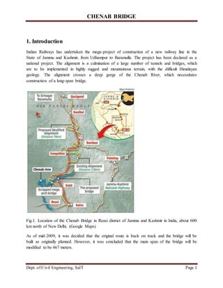
  • 1. CHENAB BRIDGE Dept. of Civil Engineering, SaIT Page 1 1. Introduction Indian Railways has undertaken the mega-project of construction of a new railway line in the State of Jammu and Kashmir, from Udhampur to Baramulla. The project has been declared as a national project. The alignment is a culmination of a large number of tunnels and bridges, which are to be implemented in highly rugged and mountainous terrain, with the difficult Himalayan geology. The alignment crosses a deep gorge of the Chenab River, which necessitates construction of a long-span bridge. Fig.1. Location of the Chenab Bridge in Reasi district of Jammu and Kashmir in India, about 600 km north of New Delhi. (Google Maps) As of mid-2009, it was decided that the original route is back on track and the bridge will be built as originally planned. However, it was concluded that the main span of the bridge will be modified to be 467 meters.
  • 2. CHENAB BRIDGE Dept. of Civil Engineering, SaIT Page 2 The current paper describes mainly the conceptual and structural design of the Chenab Bridge. In the design work the National Codes of India, Indian Railway Standards (IRS), Indian Road Congress (IRC) recommendations and Indian Standards (IS) have been supplemented with International standards like British Standards (BS), standards of the International Union of Railways (UIC) and some national codes. 2. Need for the Chenab rail bridge Travelling in and around the mountainous terrain of Jammu and Kashmir has been a great difficulty for locals. An urgent need to provide better transportation facilities was recognized by the Government of India. Construction of a national railway project that will connect J&K with the rest of India was therefore proposed. The JUSBRL project was launched in 2003 as part of this proposal. The 345km-long railway line between the Jammu and Baramulla regions will enhance mobility within the state and across India. The railway line will traverse along Jammu-Udhampur-Katra-Quazigund-Baramulla. Construction of the Jammu to Udhampur section was completed and opened in April 2005. Work is progressing on the Udhampur to Baramulla section. The project includes construction of several bridges and tunnels along the route, of which Chenab Bridge is one. It is will span across the deep Chenab river and provide access to the Kashmir valley from Udhampur. 3. Description of the Chenab Bridge The Chenab Bridge is a steel railway arch bridge with a total length of 1315 meters. It is formed by an approach bridge, which is 530 meters long, and an arch bridge, which is 785 meters long. A 467 meters long steel arch (one of the longest in the world) supports the steel deck. The deck, which is 13,5 meters wide and has two tracks running on it, is located about 320 meters above
  • 3. CHENAB BRIDGE Dept. of Civil Engineering, SaIT Page 3 the surface of the river flowing in the valley. WSP Finland has the main responsibility for the Fig. 2 Description of bridge planning of the bridge. The design of the steel arch is done by subconsultant Leonhardt, Andra and Partner of Germany. 4. TOPOGRAPHICAL FEATURES The Chenab Bridge is located in the trickiest section of the Jammu-Udhampur-Srinagar- Baramulla rail route, where the typical geology consists of young Himalaya rock. That means poor quality, broken rock with dolomitic limestone and firestone lentils with a silicate content. Rock class III to V with a strength of 60 to 100MPa and a volume weight of 2.7t/m³ is encountered. The RMR (rock mass rating) index amounts to 40 to 60. 5. DESIGN 5.1 BASIS NOTES FOR THE CHENAB BRIDGE After many deliberations, taking into account aesthetics, economy, and availability of local expertise and construction materials, the Chenab Bridge was designed as a large span single arch steel bridge with approach viaducts on either side. The arch is two-ribbed, fabricated from large steel trusses. The chords of the trusses are sealed steel boxes, internally stiffened and filled with
  • 4. CHENAB BRIDGE Dept. of Civil Engineering, SaIT Page 4 concrete to assist in controlling wind-induced forces on the bridge. Another advantage of concrete filling is that internal painting will not be required. The number of bearings has been minimized, particularly on the approach viaduct, through the use of continuous construction. This is advantageous, as it reduces the maintenance and inspection efforts, and improves the riding quality. The viaduct piers are of concrete, while the piers near the arch are of steel. The design of major arch rail bridges requires considerations of a number of additional parameters, such as fatigue, global stability, second order effects, composite action, etc. It also requires that such a bridge is designed to achieve a consistent level of reliability for all load cases, and that the design standards match the construction standards. Indian construction standards such as the Indian Railway Standards (IRS), the Indian Road Congress (IRC) and the Indian Standards (IS) were found inadequate for the large spans of the Chenab Bridge. For example, the Indian Railway Standards (IRS) is primarily intended for simply supported bridges with spans up to 100m (although these have been successfully used for higher spans up to 154m). The spans for the Chenab Bridge greatly exceed this limit, and are continuous. Therefore, to assure a safe design, Indian national standards have been supplemented with International standards such as British Standards (BS), International Union of Railways (UIC) and Euro. Also, many experts throughout the globe, based on their versatile and relevant experience, have been involved in order to make the building project a success. Following are some of the design considerations taken into account:  Limit state philosophy of design has been decided to be followed as per BS codes  Computation of wind load effects as per wind tunnel tests  Site specific seismic spectra developed by Indian Institute of Technology (IIT) Roorkee  Provision of Euro code 8 for ductility detailing of very tall and hollow rectangular RCC piers  Provision of long welded rail (LWR) over the bridges and resulting force calculation as per UIC – 774-3R guidelines  Blast resistant design has been used  Design checking for fatigue as per BS codes  Deformation limits as per comfort criteria of UIC – 776-2R and UIC 776 -3R guidelines  Redundancy provided in the structures, for lower level of operation during mishaps and against collapse in extreme cases of one pier failure The Quality aspect has been emphasized, as the quantum of fabrication and welding is colossal. Mostly indigenous material compliant to IS codes has been planned to be used, whereas for the design, international codes have been referred, which means the Quality Control work is still difficult. 5.2 Design Concept As per the Contract Agreement, the design of the bridge had to confirm to the relevant IRC standards applicable and as revised from time to time on the date of tender.
  • 5. CHENAB BRIDGE Dept. of Civil Engineering, SaIT Page 5 The existing structure and landscapes of the site has been fully taken care of so that obstruction due to the Piers would be negligible. The fixing of the foundation size had also been given due weightage so that the edge on the water side was maintained. All the components of the bridge were designed to work together and complement each other aesthetically. It had further been ensured that the Substructure and the Superstructure box have the same width i.e. 5.00 m in Cross Section so that the slenderness and sleekness of the structure is maintained. This was done to enhance its aesthetics, which in fact is a visual delight as actually seen. Superstructure has been given parabolic profile in elevation. Soffit Slab thickness also varies parabolically, from 300 mm to 1250 mm. Pier Head segment has been provided with suitably designed diaphragm block. Soffit has been thickened at junction with diaphragm block to take care of large compressive forces. Loads For pre-stressing, characteristic values Pm (x,t) have been used. For erection stages, relevant values of t have been used. For the finished structure, values of t just after completion and after 70 years. The variable loads considered are: Traffic Load : 1lane of class 70R or 2 lanes of class A according to IRC:6-2000, clause 207.1. Footway loading: according to IRC:6-2000, CLAUSE 209.4 P= (P’-260+4800/L)(16.5-W)/15 P’=500KG/M2 L= length in M of relevant parts of influence lines W= width of footway Braking Force : 20% of the first train load and 10% of the load of succeeding trains, train loads in one lane only being considered. Water Current :Horizontal forces from water current are based on mean velocity of 3.5m/s. Temperature :Concrete structures: Uniform temperature change in the structure: ±250C Non uniform temperature distribution in as per positive and reverse temperature differences as per clause 218.3 of IRC:6-2000. Erection Loads: Traveler type top truss Weight- 650 kN
  • 6. CHENAB BRIDGE Dept. of Civil Engineering, SaIT Page 6 Point of application from support - Tip of Cantilever Imbalance due to selfweight Dimensional tolerance - 5% Random Loading Equipment and Personnel -0.5 kN/m2 Vertical Wind pressure 0.55 kN/m2 Concentrated load attip of Cantilever - 50kN Bearing Friction: Sliding bearings (Teflon on stainless steel) 5% of the actual characteristic bearing load. Accidental Loads from Earthquake : The site is in zone V and Zone factor 0, 36 5.3 Design of bridge The concept of steel arch was clearly the preference of the Client (Fig. 4). In the tender phase several numbers of alternatives of the steel arch and also a concept of a cable-stayed bridge were studied. In the railway line another steel arch bridge, the Anjikhad Bridge, will be built. It follows a similar concept at a smaller scale.
  • 7. CHENAB BRIDGE Dept. of Civil Engineering, SaIT Page 7 Fig. 3 drawing of the bridge The arch and arch piers of the Chenab Bridge will be made from large steel trusses. In order to provide minimum wind resistance, it was initially intended to use pipe sections for all members of the arch. In order to facilitate production on site, the chords of the trusses and the diagonals were later modified to become sealed steel boxes (Fig. 5). All other members including the secondary members were kept circular, which greatly simplifies the connection details. The chord members will be filled with concrete in order to assist in controlling wind-induced forces on the bridge by improving the damping ratio and stiffness. The concrete fill also enhances the overall robustness. In the arch portion, the superstructure is supported on steel piers with a height of up to 120 meters. Expansion joints are provided at the end abutments and at Pier S70 that separates the main arch span from the approach bridge. At this location there is also a change in the deck height. The point of longitudinal fixity of the arch bridge deck is at the arch Centre, where the forces are transmitted most efficiently and the displacements at either end are minimal. The superstructure is a plate girder with a closed deck, where rails are connected. The closed deck keeps the rainwater out and provides mostly dry environment below the deck. Wind noses of the deck are provided in main arch portion.
  • 8. CHENAB BRIDGE Dept. of Civil Engineering, SaIT Page 8 Fig 4 .- Details of the steel arch. 5.4 Superstructures The superstructure has been constructed progressively from the piers. The PSC box depth varies from 9.75 m at root to 3.4 m at the center of span 2. The Span-depth ratio for mid span at root is 16.4 m and at mid span it is 47 m. The out to out width of the box is 12 m and carriageway width caters to two lane traffic with 1.5 m footpath on either side separated by crash barrier. The soffit profile of the box varies parabolically. The pier-head segment was 5.0 m wide. First 5 segments have been proposed to be constructed on the staging as firm ground for staging was available. Also at 11m distance from pier location, a pier on the central span side was available to be used as temporary support for ensuring stability during construction. The segment-width varies from 2.25 m to 4.5 m. The weight of each segment has been restricted to 130 t owing to requirements of bridge traveler unit. In span 1 and 3, the box has been filled up with PCC to a length of 14.5 m to ensure stability during service and to prevent uplift on abutment bearings. Access opening has been provided through the diaphragms and fill-portion. 5.5 Pre-stressing Cables For pre-stressing, 62 no. of cables, at junction of web and deck slab have been used. For cantilever erection of the bridge. 31 no. of pre-stressing cables on either side of the box have been concentrated at the junction of web and deck slab. The provision for future pre-stressing has been kept by providing 5 no. of 110 mm diameter holes in the diaphragm
  • 9. CHENAB BRIDGE Dept. of Civil Engineering, SaIT Page 9 5.6 Blisters The blisters have been used either in the web or essentially at junction of web with deck or soffit slab. As an exception, near the abutment, the blisters have been provided in the soffit of deck slab to take care of forces due to temperature variation. At pier locations, the diaphragm wall is 1200 mm thick and bottom part has been provided as solid block of size 4m x 4 m , considering temporary fixing for stability. 5.7 Substructure and Foundation The abutments consist of hollow box and piers consist of hollow rectangular section on raft foundations. The pier section is tapered near foundation for a height of 4.5 m for effective dispersion of the load on the foundation area. (a) Abutments: The box size of A1 is 12 m x 10.5 m. It is divided into 9 cells. The box size of A2 is 12 m x 7.6 m. It is divided into 6 cells. The wall thickness is 750 mm on front and back and 500 mm for side walls. Internal walls are 450 thick. (b) Piers P1 & P2: The hollow section size is 6.6 m x 5.0 m (outer dimensions). The raft foundation size for piers is 14.25 m x 17.0 m. 5.8 Stability during Construction During construction, stability cables, 4 no. of 19 T 15 have been provided to prevent uplift at abutment which have been used to anchor the superstructure to abutment while span 1 has been completed and superstructure has been made to rest on bearings on Abutment in order to progress the construction on central part of 40 m of span 2 of 160 m. The Stability Cables had been stressed to 60% of UTS value. These cables are proposed to be removed after stressing of 2 no. of continuity cables. Remaining continuity cables shall be stressed only after de- stressing of continuity cables. A beam has been provided on top to prevent upward thrust due to live load during service. 6. Construction of bridge The bridge’s construction principle entails a large bridge arch with access viaducts at each side. The large arch is designed as a 2-fold ribbed arch comprising steel girders with scaffolding braces produced on the spot. Altogether 5 bridge pillars for the access viaducts are made of steel and 13 of concrete. The largest pillar is 120m high. Some 25,000t of steel, 4,000t of reinforcing steel and 74,000m³ of concrete are being processed. All steel structures are produced in 4 workshops and the concrete at a plant on the site. Altogether around 0.85 million m³ of earth will be moved. The steel structures of the bridge will be manufactured in workshops built in the mountains. The workshops have been moved to the building site, because there is no proper road
  • 10. CHENAB BRIDGE Dept. of Civil Engineering, SaIT Page 10 network in the challenging terrain. The longest building parts that can be delivered to the site are 12 meters in length. Therefore, four workshops have been built in the mountains. Workshops and paint shops built next to them are located on both sides of the valley. All steel materials, except for the smallest rolled profiles, are delivered to the mountains as steel boards. The insufficient infrastructure of the area causes additional problems. There is no electricity and the water of the river is not suitable for manufacturing concrete. All electricity must be produced at the site and the water is delivered from further away in the mountains. The job is also challenging, because the track has curvature in the approach bridge. In this section, the construction stage bearings have been designed in such a way that it is possible to launch the steel deck in the curvature portion as well. The bridge will consist of about 25000 tonnes of steel structures, the main portion of which will be used for the arch bridge section. First, a cable crane will be built over the valley for constructing the steel structures. The cable crane will move between pylon towers built on both sides of the valley. The crane can deliver a maximum amount of 40 tonnes of steel parts. For example, the over 100 meters long steel columns with bolted couplings will be constructed using this technique. When the long steel columns are ready, the steel deck will be pushed on top of the columns. After this, a derrick crane, which is capable of lifting about 100 tonnes, will be placed on top of the deck. The derrick will crane the arch segments from deck level to the erection front of the arch as shown in Fig . Deck erection will proceed simultaneously with the erection of the arch. Both the arch and the deck cantilever freely by up to 48 metres. When the next arch pier location is reached, temporary cables will be installed to support the arch, and the new arch pier will be constructed on the free end. The superstructure can then be supported by the arch pier and so forth until the last arch pier is reached. The very last span of the arch and the elements of the key segment will again be delivered by the cable crane; closure of the superstructure is done by means of derrick erection.
  • 11. CHENAB BRIDGE Dept. of Civil Engineering, SaIT Page 11 Fig 5. Typical arch erection by derrick crane. Fig.6 Erection of last span and key segment by cable crane. The deck of the bridge will be welded in the workshop upside down in about 8 meters long sections, because the welding points in the final structure are mainly located under the bridge. When the job is completed, the sections are turned around and delivered to the next stage of the process.
  • 12. CHENAB BRIDGE Dept. of Civil Engineering, SaIT Page 12 6.1 Securing the Slope and Preparing the Foundation Work In order to set up the foundations for the bridge in the difficult terrain, two DX800 surface top hammer drill rigs are employed. Safe excavation at both sides of the valley is being prepared on a grand scale, involving wall supporting, rock anchoring and drilling for foundations. The earth- securing activities are being carried out at both sides of the river in similar fashion. Terraces are created in individual working steps in extremely steep terrain. The DX800 is operating on such a terrace under extreme conditions. Following vertical supporting operations on the slope, an initial layer of rock is removed by blasting and carried away. The horizontal drill holes for securing the steep walls are undertaken using grouting mortar in a very constricted area. In this manner, all further working stages are carried out in order to reduce the rock to the desired height, upon which the foundation for the next pillar can be erected. The working area on which the DX800 stands is a maximum of 4.50m wide from the rock to the abyss. Nonetheless, drilling (Fig.7 rock bolting to stabilize the slope) Extending to 6m must be possible. 6.2 Foundations The work of the execution of the foundation of PI and P2 had been physically started on the ground by 5th Jun & 15th Jun 2006 respectively and plants & equipments placed as per the original schedule. The excavation was only possible by drilling and blasting as very hard conglomerate strata in both the foundations of piers P1 & P2 was encountered after the removal of the initial overburden of Earth upto a depth of about 3 m. The foundation of pier
  • 13. CHENAB BRIDGE Dept. of Civil Engineering, SaIT Page 13 P1 & P2 had been completed and lean concrete laid after conducting plate load bearing test were carried out on 01 Sept 2006 at RL 311 for P1 and at RL 309.5 for P2. Simultaneously Fig 8 size of the foundation for piers Execute of abutments were also progressed. The work had been taken up in full swing. Due to heavy rains and high floods after placing the reinforcement in both the Piers there was a set back due to High water level because of floods and the pits were filled with mud debris etc. However the surface were cleaned by deploying adequate people round the clock and concreting of the foundation of both piers completed by 14 Oct 2006. Further work also continued simultaneously. The pier P1 and P2 had crossed HFL (at RL330.40M) on 11 Dec 06 and 14 Dec 06 respectively and further works were not possible for want of bearing whose Anchor bars were to have been embedded in the Pier cap. Simultaneously execution of abutments were also progressed and lean concrete in Al and A2 were completed by 15 Dec 06 as well as concreting work in foundation on 23 Dec 06 and further work were continued.
  • 14. CHENAB BRIDGE Dept. of Civil Engineering, SaIT Page 14 6.3 Piers and Super Structure after the construction of the foundation the next step is construction of piers and the super structure. The tallest pier is 133.7m. 7. Challenges for the Equipment Fig. 8 For a maximum bench height of 20m, the DX800 is equipped with an auto rod changer for longhole drilling. The hydraulic rollover in the drilling boom is recommended for horizontal
  • 15. CHENAB BRIDGE Dept. of Civil Engineering, SaIT Page 15 drilling. The accurate angle and depth indicator helps for rock bolt drilling in a perpendicular wall surface and inclined drilling. Horizontal drilling up to 6m in height as well as setting the rock bolts is possible thanks to the articulated boom with auto rod changer. The very narrow bench surface for drilling does not represent a problem on account of the drill swinging arrangement of the revolving super structure on the DX800’s axis (180 degrees). The problem of the very extreme, varying climatic conditions encountered at the Chenab Bridge jobsite in the Himalayas is solved with a safe and comfortable operator cabin. The auto dust collector prevents dust spreading during drilling. Compressed air is available at all times with the on-board compressor for efficient flushing of drilled hole. The powerful rock drill with a performance of 21 KW caters for a high drilling volume at the jobsite. The operating costs per metre are minimized with fuel-efficient drilling, which leads to lower fuel consumption, but more drilling metres. The DX800 is not so big in terms of size, at 2.5m in width, 3.6m (3.2m) in height and 7.2m (10.7m) in length. The crawler is the best solution in view of stability, given the difficult ground conditions. One of the most important features is also that the precision of place and direction of the drill holes is very high. And to top it all off, the drilling speed of the DX800 is much higher than that of traditional drilling equipment. In terms of rock tools, Afcons uses a button bit with regular skirt, 102mm diameter and a lifecycle of 700m. The rods are 3m long used with extension rods T51 and coupling sleeves T51 both with a lifecycle of 2,000m. 8. The World’s Largest Cable Crane What is currently the world’s largest cable crane traverse facility was installed to cope with the high loads on site and cater for renovation and maintenance work. Pylons 100 and 120m long stand on the east and west side of the Chenab Valley. The span width of the steel cable between the pylons amounts to 915m. Two 40m long traverses are operated in parallel, each possessing a safe working load (SWL) of 20t.
  • 16. CHENAB BRIDGE Dept. of Civil Engineering, SaIT Page 16 Fig. 9 view of the cable crane 9. Bridge construction and challenges faced The bridge is being constructed in one of the most complicated and isolated terrains. One of the biggest challenges involved was construction of the bridge without obstructing the flow of the river. Approach roads, five kilometres in length, were constructed to reach the foundations of the bridge. The deck of the bridge is partly in straight horizon and partly in curves. It is located on a transition curve with changing radius. Construction is therefore being carried out in stages following the gradual change in the alignment. This is the first time a bridge is being constructed incrementally on a transition curve. Cable cranes and derrick will be used to construct the bridge. The cable cranes used for the project will be the largest in the world. Construction of the bridge is expected to require 25,000mt of steel, 4,000mt of reinforced steel, 46,000m³ of concrete and eight million m³ of excavation. Jammu and Kashmir region is most sensitive region in terrorist attack. Thus it is most challenging task to convince the engineers and labours to work at the site.
  • 17. CHENAB BRIDGE Dept. of Civil Engineering, SaIT Page 17 10. One of the Highest Railway Bridges in the World The steel arch-shaped bridge over the River Chenab can lay claim to several superlatives. According to the contractors, it is one of the highest bridges of its kind in the world. One of the world’s biggest cable cranes was developed and built to straddle the valley for the complex assembly of the prefabricated steel parts. The Chenab Bridge project is owned by the Konkan Railway Corporation Ltd. (KRCL), an enterprise of the Indian government. KRCL floated international competitive bidding (ICB) in order to find a qualified contractor to smoothly execute the project. Afcons emerged as one of the most qualified bidders, winning the execution contract. This special and strategic project was given the green light after extensive research involving aesthetic and economic aspects as well as logistics and weather conditions. In the process, the rocky, fissured terrain of the Himalayas had to be taken into account as well. Work on the bridge, which is valued at roughly USD 92 million, started in 2005 (with a 3-year-long interruption for rescheduling); the project was restarted in 2011 and is due to be completed in 2016. The bridge is expected to have a service life of 120 years. Fig 9 view of the Chenab bridge
  • 18. CHENAB BRIDGE Dept. of Civil Engineering, SaIT Page 18 When finished, the bridge will span the Chenab River at a height of 359 m (1,178 ft) above the river, making it the world's highest rail bridge 11. Contractors involved in constructing the Indian bridge Amberg Engineering was appointed to carry out review work of the alignments. Konkan Railway Corporation is executing the project. Design and construction of the bridge was awarded to a joint venture of Afcons Infrastructure, Ultra Construction & Engineering Company of South Korea and VSL India in 2004. Finland-based WSP Group and Germany-based Leonhardt Andra and Partners are the consultants for the project. VCE Consult ZT-GmbH designed the pylons of the bridge. Jochum Andreas Seiltransporte installed the cables for the pylon. AkzoNobel was awarded the painting services contract for the bridge. 12. Maintenance Regular painting of such bridges is an intimidating task; hence, a painting scheme has been developed, having life over 15 years, compared to approx. 5 to 7 years of life in most of the Indian railway bridges. 13. Innovations During the Design and construction of this bridge, a number of innovations/firsts have been achieved. The list of innovations/firsts is as under: • The Heaviest bearings ever used in any bridge in India. Total weight of bearings is 42.0 MT and maximum capacity 4000 MT. Physical Weight of bearings is shown Table 4. • Longest span Pre-stressed Concrete bridge (160m) in India. • The fastest construction of any P.S.C structure in India for a bridge of 280 m length. • The shortest time cycle consistently achieved for the construction of each pair of segments (06 days).10.13 • Concrete Mix with minimum cement content of 400 Kg for M 50/43 grade used in India along with Admixture (cement used O.P.C 43 Grade). Fe 500 steel for Reinforced bars used for the first time in India in a cantilever construction bridge. • Pre-stressing being done after only 60 hours of casting of each segment.
  • 19. CHENAB BRIDGE Dept. of Civil Engineering, SaIT Page 19 • The concrete below bearings done by Conbextra grout for the first time. Self Compacting Concrete (S.C.C) used for the first time for concrete below the bearings. • The depth of Girder in the Central Portion is 3.40M for 160 m span. This has a high span depth ratio of more than 47. • Total concreting with automatic batching concrete plant and concrete pump. Concrete mixed transported and placed untouched by hand for a cantilever construction river bridge in India. • Use of Electrical Passenger Hoist for Inspection used first time in India for river bridge. • Use of surface retarder & curing compound for cantilever bridge. • 43 Grade Cement used for 50 MPa concrete for the first time. • Fastest Approval of Founding levels for execution. • Segments on both sides of the Pier concreted simultaneously balancing the weights by doing synchronized casting for the first time. 14. Conclusions and Recommendations Technical and administrative decisions should be taken on merit and based on the available technology after proper analysis. By taking bold decisions not based on hiding or camouflaging the acts of the past mistakes this bridge has seen the light of the day. Our felicitation to all concerned. Conclusions are as follows: 1. Sites where the velocity of the flow of water is high i.e. more than 4M m/s and where the bed is conglomerate, soft stone, bouldary etc. (in short difficult to penetrate) such type of construction of continuous long span bridges are recommended. 2. Other countries are achieving construction of spans of around 200 m. We should also explore constructing such large spans. 3. The grade of concrete designed for used in this bridge for superstructure was M50. It is recommended that for such large spans grade of around M80 and above should be targeted. This will reduce the cost of construction as well as the dead load of the superstructure. Incidentally, in this Bridge M50 was achieved in the first trial mix with minimum cement of 400 kg/m3 content and normal admixtures. 4. Continuous survey of the levels and centre line with the help of total station is a must for these type of structures. In this bridge continuous checking of deflections and the centre line as per the approved drawings as conceived by the design consultant and as per the approved
  • 20. CHENAB BRIDGE Dept. of Civil Engineering, SaIT Page 20 drawings and as actually observed matched like a ‘T’ and there were no variations. Thus the linking segment was cast at the same level on both ends in elevation with a matching centre line. 5. Time is the essence of the contract and ‘Money is the cause of it’. The department by its action in this bridge has shown that in spite of stiff financial conditions there were no conflicts and Perfect Harmony was maintained during execution. 6. For time bound important projects, team of Officers who start the project should be mad to complete the same to ensure continuity of command, accountability, efficiency and satisfaction of the team. 7. When the 22nd segments were facing each other and the shuttering of the 23rd segment i.e. the linking segment was to have been placed there was no level difference and the levels matched on both tips to the nearest millimeter both in plan (centre line) as well as in elevation. This was possible because every day the levels were maintained by a team of surveyors with the help of total station. These levels were sent to the Design consultant who monitored these personally. In fact after the concreting of each segment the levels actually measured and as envisaged by the designer fitted almost like a ‘T’. This proves that the parameters fixed by the Design consultant and the parameters as actually achieved during execution were complimenting each other. The cables were so placed that almost all the cables were straight and without any kink. Thus pre-stressing results were exactly as shown in approved drawings both in terms of extension and gauge pressure. 8. On the advise of the Proof Consultants the reinforcements as required as per detailed design in this bridge was increased substantially in the Blisters. This led to early stressing without any problems/distress. It is recommended that reinforcements in blisters should be increased. 9. The bridge scheme was unequal, the river side span (half) was 80 m and the earth side was 60 m. Thus unbalanced moments had to accommodate in the Earth side by additional dead load. The difficulty in construction, and the risk of unequal moments could have been avoided if the land side span was made equal i.e. increased from 60 m to 80 m. This action would have reduced the risk without any increase in costs as executed structure has costed more. 10. The designer of this bridge has scrupulously followed the use of Tapering Sections, Haunches, and Chamfers for better and smoother flow of forces to avoid stress concentration and/or cracking. This method although required as per code has almost been forgotten. It is recommended that wherever force transfer is taking place, the old, tried and tested methods of easing of stress should be scrupulously followed. 11. During last decade technology has advanced exponentially. Hence for all problematic bridges lying incomplete elsewhere adoption and adaption of the latest technology will
  • 21. CHENAB BRIDGE Dept. of Civil Engineering, SaIT Page 21 definitely expedite completion as has been achieved in Chenab bridge if problems are reviewed afresh. 15. References 1. "World's highest rail bridge to come up across Chenab river". Hindustan Times. 2013-02-17. Retrieved 2013-02-17. 2. "Chenab Bridge". Trimble Solutions Corporation. 25 June 2016. 3. "Chenab bridge will be highest in the world". Online edition of The Hindu, dated 2008-01-17. 4. J&K to have world's tallest bridge". TOI News. 2007-11-05. Retrieved 2008-01-14