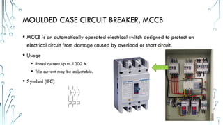
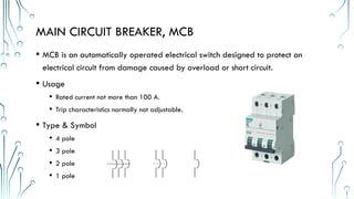
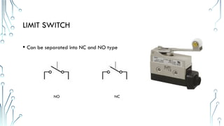
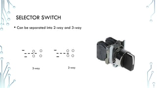
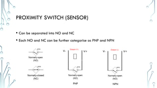
BASIC ELECTRICAL
IMPORTANT ELECTRICAL COMPONENT
PROTECTION COMPONENT
• Moulded Case Circuit Breaker, MCCB
• Main Circuit Breaker, MCB
• Electric Leakage Circuit Breaker, ELCB
• Residual Current Circuit Breaker, RCCB or Residual Current Device, RCD
• Fuse
MOULDED CASE CIRCUIT BREAKER, MCCB
• MCCB is an automatically operated electrical switch designed to protect an
electrical circuit from damage caused by overload or short circuit.
• Usage
• Rated current up to 1000 A.
• Trip current may be adjustable.
• Symbol (IEC)
MAIN CIRCUIT BREAKER, MCB
• MCB is an automatically operated electrical switch designed to protect an
electrical circuit from damage caused by overload or short circuit.
• Usage
• Rated current not more than 100 A.
• Trip characteristics normally not adjustable.
• Type & Symbol
• 4 pole
• 3 pole
• 2 pole
• 1 pole
MAIN CIRCUIT BREAKER, MCB
4 pole MCB
2 pole MCB
3 pole MCB
1 pole MCB
RESIDUAL CURRENT CIRCUIT BREAKER, RCCB OR RESIDUAL
CURRENT DEVICE, RCD
• RCCB or RCD is the new name that specifies current operated (hence the new name
to distinguish from voltage operated).Phase (line) and Neutral both wires connected
through RCD.
• It trips the circuit when there is earth fault current.
• The amount of current flows through the phase (line) should return through neutral .
• It detects by RCD. any mismatch between two currents flowing through phase and
neutral detect by -RCD and trip the circuit within 30Miliseconed.
• If a house has an earth system connected to an earth rod and not the main incoming
cable, then it must have all circuits protected by an RCD (because u mite not be able
to get enough fault current to trip a MCB)
RESIDUAL CURRENT CIRCUIT BREAKER, RCCB OR RESIDUAL
CURRENT DEVICE, RCD
• If a house has an earth system connected to an earth rod and
not the main incoming cable, then it must have all circuits
protected by an RCD (because u mite not be able to get
enough fault current to trip a MCB)
• RCDs are an extremely effective form of shock protection
• The most widely used are 30 mA (milliamp) and 100 mA
devices. A current flow of 30 mA (or 0.03 amps) is sufficiently
small that it makes it very difficult to receive a dangerous
shock. Even 100 mA is a relatively small figure when compared
to the current that may flow in an earth fault without such
protection (hundred of amps)
RESIDUAL CURRENT CIRCUIT BREAKER, RCCB OR RESIDUAL
CURRENT DEVICE, RCD
• Normally located after
Main incoming MCB
before distribution MCB
Main incoming MCB
RCCB/RCD
Distribution MCB
ELECTRIC LEAKAGE CIRCUIT BREAKER, ELCB
• Phase (line), Neutral and Earth wire connected through ELCB.
• ELCB is working based on Earth leakage current.
• But RCCB is not having sensing or connectivity of Earth, because
fundamentally Phase current is equal to the neutral current in single
phase. That’s why RCCB can trip when the both currents are deferent
and it withstand up to both the currents are same. Both the neutral
and phase currents are different that means current is flowing
through the Earth.
FUSE
• Fuses are the protectors, whenever the heavy amount of current or an
excessive current flow is there in an electrical circuit, the fuse melts and it
opens the circuit and disconnects it from the power supply.
• Fuse rating = (watts/volts) x 1.25
• Fuse Symbol
POWER CONVERSION COMPONENT
• Transformer
• AC to DC Switching Power Supply
TRANSFORMER
• A transformer is a static device which transfers
electrical energy from one circuit to another through
the process of electromagnetic induction. It is most
commonly used to increase (‘step up’) or decrease
(‘step down’) voltage levels between circuits.
• A three phase transformer could transfer a 3 phase
supply to become a single phase supply
AC TO DC SWITCHING POWER SUPPLY
• Switching power supply are used as replacements for
linear regulators when higher efficiency, smaller size
or lighter weight are required.
• They are used in modern electrical equipment for low
voltage DC power supply such as 24VDC, 12 VDC
and 5VDC.
AC TO DC SWITCHING POWER SUPPLY CIRCUIT
Step down to
required
voltage
RELAY
• Magnetic Contactor Relay (Machine Control Relay)
• Thermal Overload Relay
• Timer Relay
• General purpose relay
• Solid State Relay
MAGNETIC CONTACTOR RELAY
• A high voltage and ampere ON/OFF switch control by electric signal (Either
AC or DC)
• Contactor can be separated into
2 section:
1. Power Circuit
2. Control Circuit
Power circuit is function as gate to
stop or allow the power from
passing through
Control circuit is function as
switch to control the gate to
open or close
MAGNETIC CONTACTOR RELAY
Other than contact point,
Magnetic contactor also
have NC and NO point
which could use for control
circuit usage
Note:
NC – Normally close
NO – Normally open
MAGNETIC CONTACTOR RELAY – CONTROL
CIRCUIT
• Control circuit
• AC coil circuit
• DC coil circuit
• Holding circuit
• NO circuit
• NC circuit
THERMAL OVERLOAD RELAY
• Thermal overload relays are economic
electromechanical protection devices for the
main circuit. They offer reliable protection
for motors in the event of overload or
phase failure. The thermal overload relay
can make up a compact starting solution
together with contactors.
TIMER RELAY
• Time delay relays are simply control relays with a time delay built in. Their
purpose is to control an event based on time. The difference between relays
and time delay relays is when the output contacts open & close: on a control
relay, it happens when voltage is applied and removed from the coil; on time
delay relays, the contacts can open or close before or after some time delay.
GENERAL PURPOSE RELAY
• Function similar to Magnetic
contactor. Using as a gate to control
low voltage signal or switching
signal
• Relay can be separate into
• Power circuit
• Control circuit
• AC coil
• DC coil
Power circuit
Control circuit
SOLID STATE RELAY
• An electronic switching device that
switches on or off when a small external
voltage is applied across its control
terminals. It serves the same function as an
electromechanical relay, but has no moving
parts.
SWITCH AND BUTTON
• Limit Switch
• Push button
• Selector Switch
• Proximity Switch (Sensor)
• Emergency Stop button
LIMIT SWITCH
• Can be separated into NC and NO type
NO NC
PUSH BUTTON
• Can be separated into NC and NO type
NC
NO
SELECTOR SWITCH
• Can be separated into 2-way and 3-way
3-way 2-way
PROXIMITY SWITCH (SENSOR)
• Can be separated into NO and NC
• Each NO and NC can be further categorise as PNP and NPN
V+
V- V+
V-
PNP NPN
Output (+) Output (-)
PROXIMITY SWITCH (SENSOR)
EMERGENCY STOP BUTTON
• Can be separated into NC and NO
NO NC

Basic Machine Electrical Panel Components.pptx

  • 1.
  • 2.
    PROTECTION COMPONENT • MouldedCase Circuit Breaker, MCCB • Main Circuit Breaker, MCB • Electric Leakage Circuit Breaker, ELCB • Residual Current Circuit Breaker, RCCB or Residual Current Device, RCD • Fuse
  • 3.
    MOULDED CASE CIRCUITBREAKER, MCCB • MCCB is an automatically operated electrical switch designed to protect an electrical circuit from damage caused by overload or short circuit. • Usage • Rated current up to 1000 A. • Trip current may be adjustable. • Symbol (IEC)
  • 4.
    MAIN CIRCUIT BREAKER,MCB • MCB is an automatically operated electrical switch designed to protect an electrical circuit from damage caused by overload or short circuit. • Usage • Rated current not more than 100 A. • Trip characteristics normally not adjustable. • Type & Symbol • 4 pole • 3 pole • 2 pole • 1 pole
  • 5.
    MAIN CIRCUIT BREAKER,MCB 4 pole MCB 2 pole MCB 3 pole MCB 1 pole MCB
  • 6.
    RESIDUAL CURRENT CIRCUITBREAKER, RCCB OR RESIDUAL CURRENT DEVICE, RCD • RCCB or RCD is the new name that specifies current operated (hence the new name to distinguish from voltage operated).Phase (line) and Neutral both wires connected through RCD. • It trips the circuit when there is earth fault current. • The amount of current flows through the phase (line) should return through neutral . • It detects by RCD. any mismatch between two currents flowing through phase and neutral detect by -RCD and trip the circuit within 30Miliseconed. • If a house has an earth system connected to an earth rod and not the main incoming cable, then it must have all circuits protected by an RCD (because u mite not be able to get enough fault current to trip a MCB)
  • 7.
    RESIDUAL CURRENT CIRCUITBREAKER, RCCB OR RESIDUAL CURRENT DEVICE, RCD • If a house has an earth system connected to an earth rod and not the main incoming cable, then it must have all circuits protected by an RCD (because u mite not be able to get enough fault current to trip a MCB) • RCDs are an extremely effective form of shock protection • The most widely used are 30 mA (milliamp) and 100 mA devices. A current flow of 30 mA (or 0.03 amps) is sufficiently small that it makes it very difficult to receive a dangerous shock. Even 100 mA is a relatively small figure when compared to the current that may flow in an earth fault without such protection (hundred of amps)
  • 8.
    RESIDUAL CURRENT CIRCUITBREAKER, RCCB OR RESIDUAL CURRENT DEVICE, RCD • Normally located after Main incoming MCB before distribution MCB Main incoming MCB RCCB/RCD Distribution MCB
  • 9.
    ELECTRIC LEAKAGE CIRCUITBREAKER, ELCB • Phase (line), Neutral and Earth wire connected through ELCB. • ELCB is working based on Earth leakage current. • But RCCB is not having sensing or connectivity of Earth, because fundamentally Phase current is equal to the neutral current in single phase. That’s why RCCB can trip when the both currents are deferent and it withstand up to both the currents are same. Both the neutral and phase currents are different that means current is flowing through the Earth.
  • 10.
    FUSE • Fuses arethe protectors, whenever the heavy amount of current or an excessive current flow is there in an electrical circuit, the fuse melts and it opens the circuit and disconnects it from the power supply. • Fuse rating = (watts/volts) x 1.25 • Fuse Symbol
  • 11.
    POWER CONVERSION COMPONENT •Transformer • AC to DC Switching Power Supply
  • 12.
    TRANSFORMER • A transformeris a static device which transfers electrical energy from one circuit to another through the process of electromagnetic induction. It is most commonly used to increase (‘step up’) or decrease (‘step down’) voltage levels between circuits. • A three phase transformer could transfer a 3 phase supply to become a single phase supply
  • 13.
    AC TO DCSWITCHING POWER SUPPLY • Switching power supply are used as replacements for linear regulators when higher efficiency, smaller size or lighter weight are required. • They are used in modern electrical equipment for low voltage DC power supply such as 24VDC, 12 VDC and 5VDC.
  • 14.
    AC TO DCSWITCHING POWER SUPPLY CIRCUIT Step down to required voltage
  • 15.
    RELAY • Magnetic ContactorRelay (Machine Control Relay) • Thermal Overload Relay • Timer Relay • General purpose relay • Solid State Relay
  • 16.
    MAGNETIC CONTACTOR RELAY •A high voltage and ampere ON/OFF switch control by electric signal (Either AC or DC) • Contactor can be separated into 2 section: 1. Power Circuit 2. Control Circuit Power circuit is function as gate to stop or allow the power from passing through Control circuit is function as switch to control the gate to open or close
  • 17.
    MAGNETIC CONTACTOR RELAY Otherthan contact point, Magnetic contactor also have NC and NO point which could use for control circuit usage Note: NC – Normally close NO – Normally open
  • 18.
    MAGNETIC CONTACTOR RELAY– CONTROL CIRCUIT • Control circuit • AC coil circuit • DC coil circuit • Holding circuit • NO circuit • NC circuit
  • 19.
    THERMAL OVERLOAD RELAY •Thermal overload relays are economic electromechanical protection devices for the main circuit. They offer reliable protection for motors in the event of overload or phase failure. The thermal overload relay can make up a compact starting solution together with contactors.
  • 20.
    TIMER RELAY • Timedelay relays are simply control relays with a time delay built in. Their purpose is to control an event based on time. The difference between relays and time delay relays is when the output contacts open & close: on a control relay, it happens when voltage is applied and removed from the coil; on time delay relays, the contacts can open or close before or after some time delay.
  • 21.
    GENERAL PURPOSE RELAY •Function similar to Magnetic contactor. Using as a gate to control low voltage signal or switching signal • Relay can be separate into • Power circuit • Control circuit • AC coil • DC coil Power circuit Control circuit
  • 22.
    SOLID STATE RELAY •An electronic switching device that switches on or off when a small external voltage is applied across its control terminals. It serves the same function as an electromechanical relay, but has no moving parts.
  • 23.
    SWITCH AND BUTTON •Limit Switch • Push button • Selector Switch • Proximity Switch (Sensor) • Emergency Stop button
  • 24.
    LIMIT SWITCH • Canbe separated into NC and NO type NO NC
  • 25.
    PUSH BUTTON • Canbe separated into NC and NO type NC NO
  • 26.
    SELECTOR SWITCH • Canbe separated into 2-way and 3-way 3-way 2-way
  • 27.
    PROXIMITY SWITCH (SENSOR) •Can be separated into NO and NC • Each NO and NC can be further categorise as PNP and NPN V+ V- V+ V- PNP NPN Output (+) Output (-)
  • 28.
  • 29.
    EMERGENCY STOP BUTTON •Can be separated into NC and NO NO NC