Downloaded 55 times

![EPP-0275-12/02 page 3/6
K
L
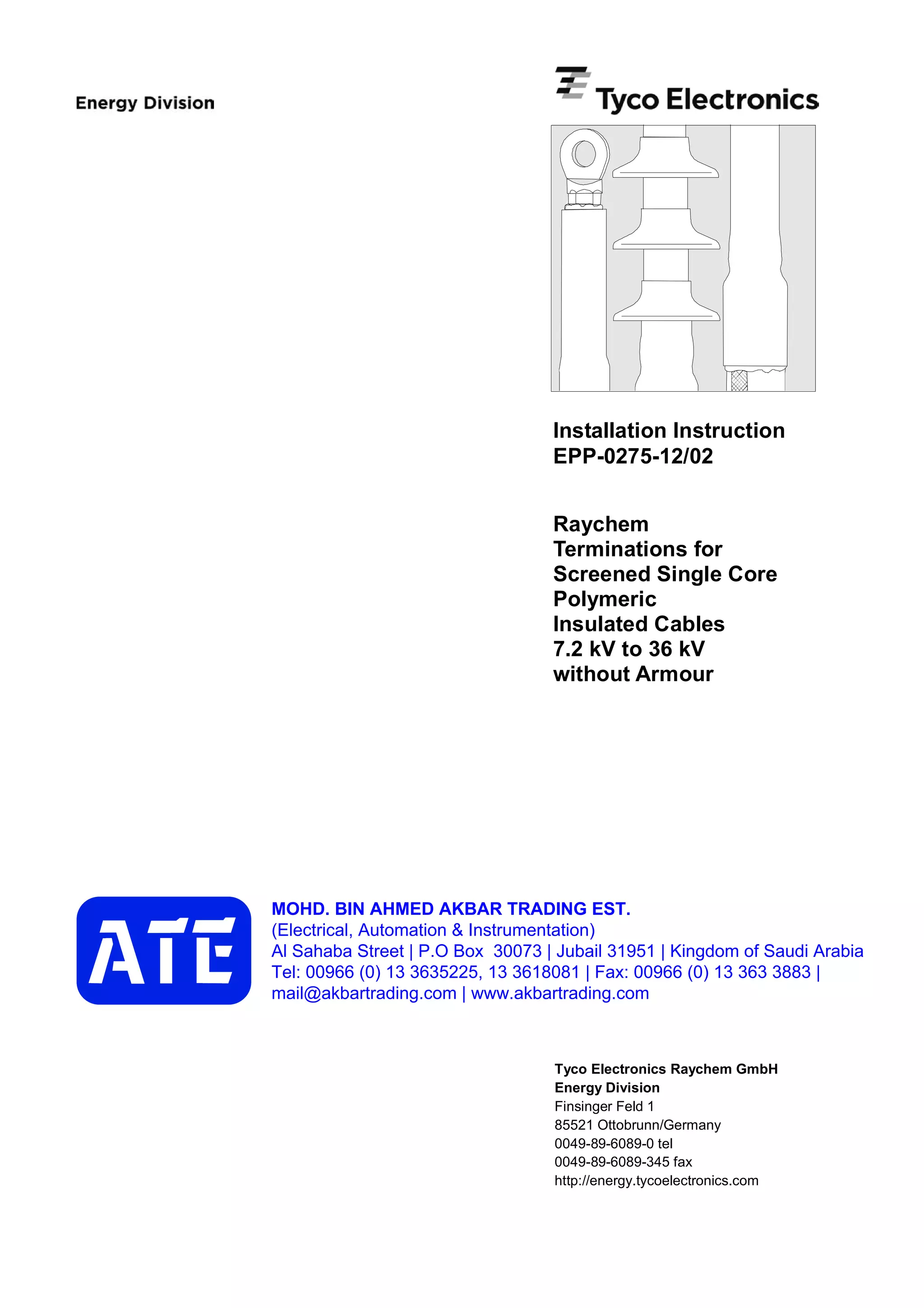
Clean 100
Thoroughly remove the core screen to
within 40 mm of the oversheath cut.
The surface of the insulation should be
free from all traces of conductive
material.
Smooth out any irregularities.
Note: Do not nick the insulation.
A3
Cut the cable to the required length.
Remove the oversheath to the
dimension L + K (Table 1). Clean
and degrease the end of the
oversheath for about 100 mm.
A1
Wrap one layer of sealant tape (red)
with a small overlap and slight tension
around the end of the oversheath for
60 mm.
Bend the shielding wires back onto the
oversheath. Avoid crossing the
individual wires. Fix the wires with a
wire binder 60 mm from the end of the
oversheath. Gather the shielding
wires together to form an earth lead.
A2
Remove the release paper and wrap
the void filling strip (yellow) around the
end of the core screen.
Cover 20 mm of the core screen and
continue onto the insulation for 10 mm.
Stretch the strip to half of its original
width to achieve a fine, thin edge onto
the insulation.
A4
Cable Preparation
A Cable with wire shield
Table 1
Max. system L L K
voltage indoor outdoor
[kV] [mm] [mm]
7,2 150 200 according
12/17.5 230 300 to depth of
24 270 350 connector barrel
36 370 500 hole + 5 mm
60
40
10
20
60
a](https://image.slidesharecdn.com/epp-0275-12021coreidtermination-160412100854/85/RAYCHEM-TERMINATION-KIT-TYCO-TERMINATION-3-320.jpg)
![EPP-0275-12/02 page 4/6
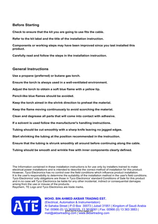
Thoroughly remove the core screen to
within 40 mm of the oversheath cut.
The surface of the insulation should be
free from all traces of conductive
material.
Smooth out any irregularities.
Note: Do not nick the insulation.
B3
Cut the cable to the required length.
Remove the oversheath to the
dimension L + K (Table 2). Clean and
degrease the end of the oversheath for
about 100 mm. Remove the metal tape
shield to within 20 mm of the
oversheath cut.
B1
Wrap one layer of sealant tape (red)
with a small overlap and slight tension
round the end of the oversheath for
60 mm. Bind and solder tack an earth
lead to the metal tape shield (or attach
the earth lead by any other equivalent
method). Fill the earth lead with solder
to form a 30 mm moisture block
20 mm from the oversheath end.
Fix the earth braid with a second wire
binder 60 mm from the end of the
oversheath.
B2
Remove the releae paper and wrap
the void filling strip (yellow) around the
end of the tape shield. Cover 5 mm of
the tape shield and continue along the
core screen onto the insulation for
10 mm. Stretch the strip to half of its
original width to achieve a fine, thin
edge onto the insulation.
B4
Max. system L L K
voltage indoor outdoor
[kV] [mm] [mm]
7,2 150 200 according
12/17.5 230 300 to depth of
24 270 350 connector barrel
36 370 500 hole + 5 mm
Table 2
B Cable with metal tape shield
Clean 100
20
60 30
40
10
20
5
60
a](https://image.slidesharecdn.com/epp-0275-12021coreidtermination-160412100854/85/RAYCHEM-TERMINATION-KIT-TYCO-TERMINATION-4-320.jpg)
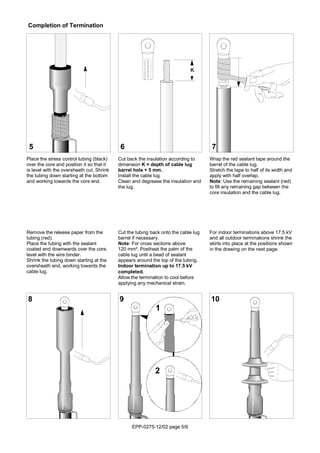
![EPP-0275-12/02 page 6/6
indoor outdoor
7.2kV 12/17.5kV 24kV 36kV 7.2kV 12/17.5kV 24kV 36kV
L1 L2 L3
d
150
80
80
80
150
80
80
80
skirt position
for reversed
installation
r
a
b
Min. clearances Max. system voltage (kV)
7,2 12 17,5 24 36
a air clearance as for local specifications
b ph/ground [mm] 10 15 20 25 35
d between skirts [mm] 10 10 15 20 25
r min. bending radius = 15xD, before bending heat cable up to approx. 70°CPlease dispose of all waste
according to environmental
regulations.
MOHD. BIN AHMED AKBAR TRADING EST.
(Electrical, Automation & Instrumentation)
Al Sahaba Street | P.O Box 30073 | Jubail 31951 | Kingdom of Saudi Arabia
Tel: 00966 (0) 13 3635225, 13 3618081 | Fax: 00966 (0) 13 363 3883 |
mail@akbartrading.com | www.akbartrading.com](https://image.slidesharecdn.com/epp-0275-12021coreidtermination-160412100854/85/RAYCHEM-TERMINATION-KIT-TYCO-TERMINATION-6-320.jpg)

This document provides installation instructions for terminating screened single core polymeric insulated cables without armour from 7.2 kV to 36 kV. The instructions summarize preparing the cable by removing the outer sheath and cleaning the insulation. They describe applying sealant tape and void filling strips before installing stress control tubing and sealing tubing. Specific steps vary depending on the cable having wire shielding or metal tape shielding. Dimensions for cutting back materials and positioning heat shrink tubing skirts are provided. General safety instructions recommend using a propane torch, avoiding scorching, and disposing of waste properly.


