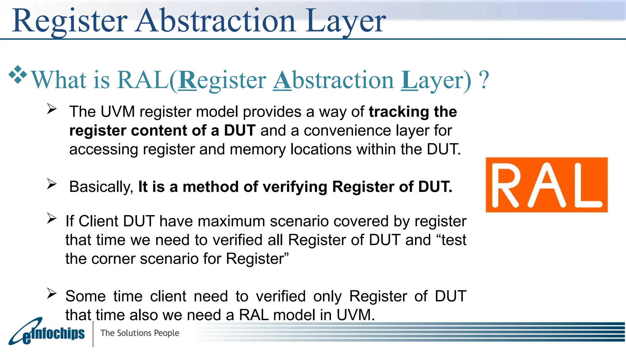
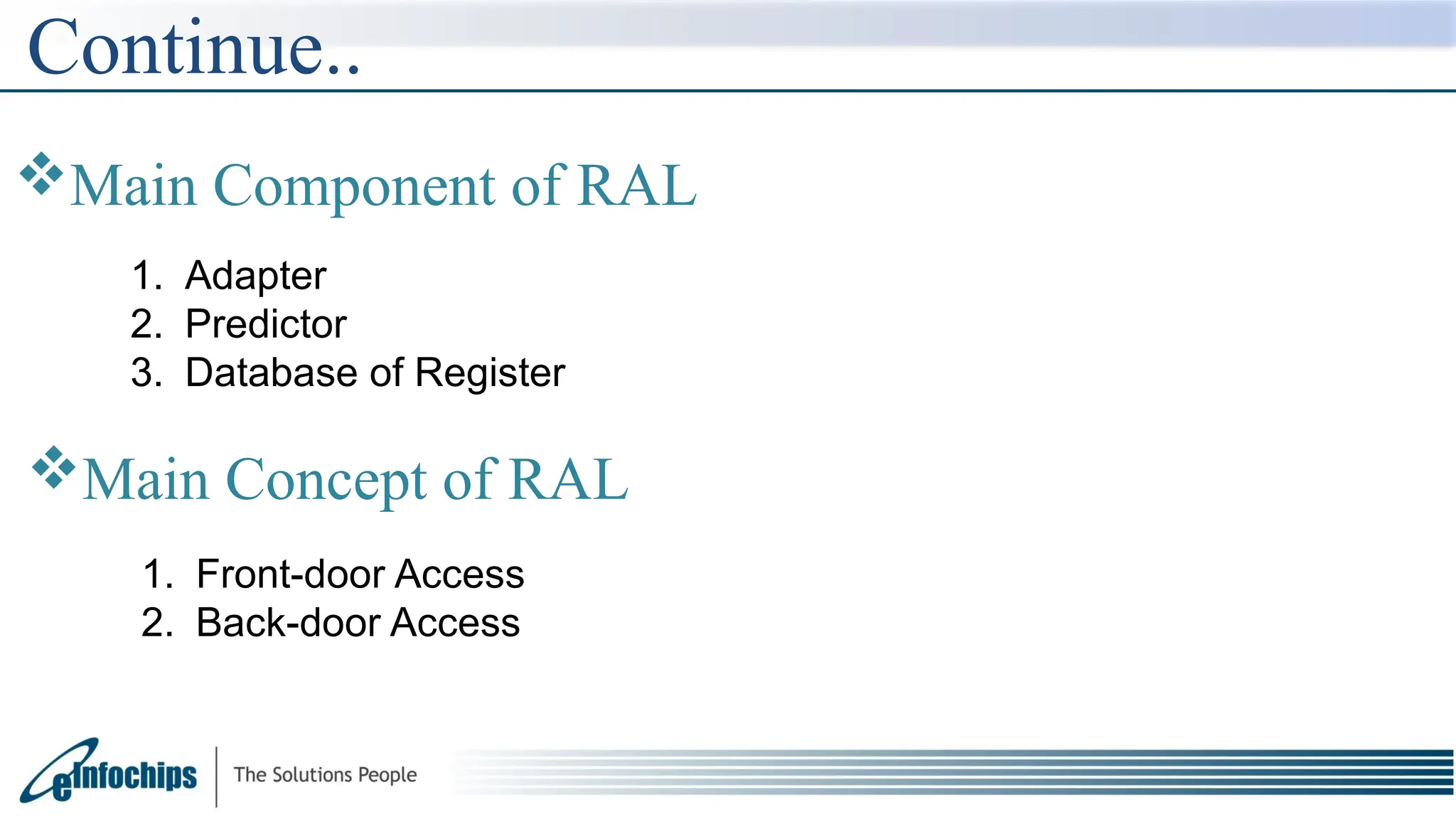
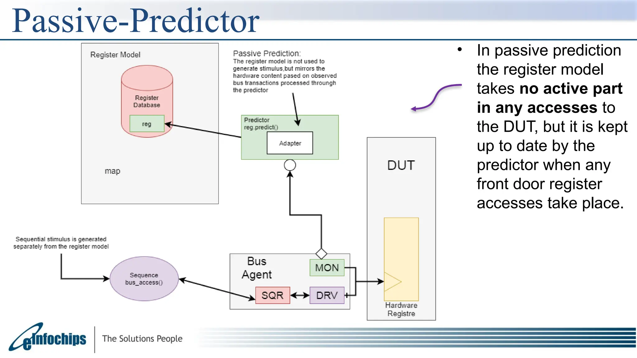
The document explains the Register Abstraction Layer (RAL) in UVM, providing a method to verify the registers of a Design Under Test (DUT) and detailing the roles of its main components, including adapters and predictors. It outlines how register model access methods function, such as front-door and back-door access, and describes key concepts, structures, and methods related to managing register fields, addresses, and memory. Additionally, the document covers aspects such as prediction modes, memory access, and different methods to read and write register values.

![Get Method
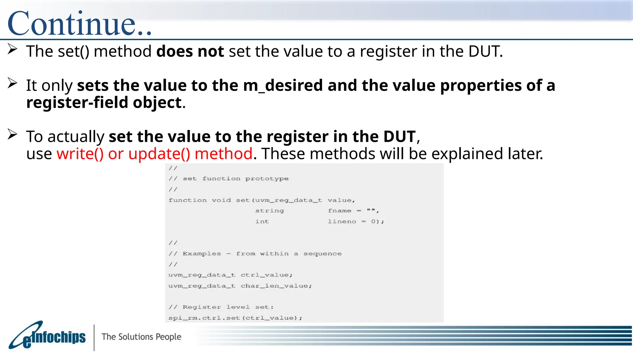
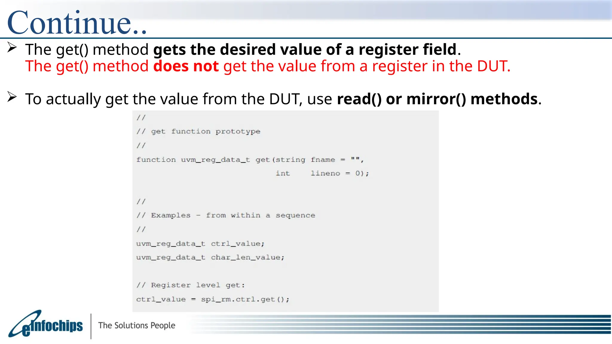
The get() method returns the calculated desired value of a register or a field.
The get_reset() retrieves
the value of
the m_reset[kind]
propery
The get_mirrored_value()
method retrieves the
value of
the m_mirrored property.](https://image.slidesharecdn.com/ralppt-250109175322-3361a874/75/ral_ral_presentation-Ral-introduction-and-detailed-information-35-2048.jpg)
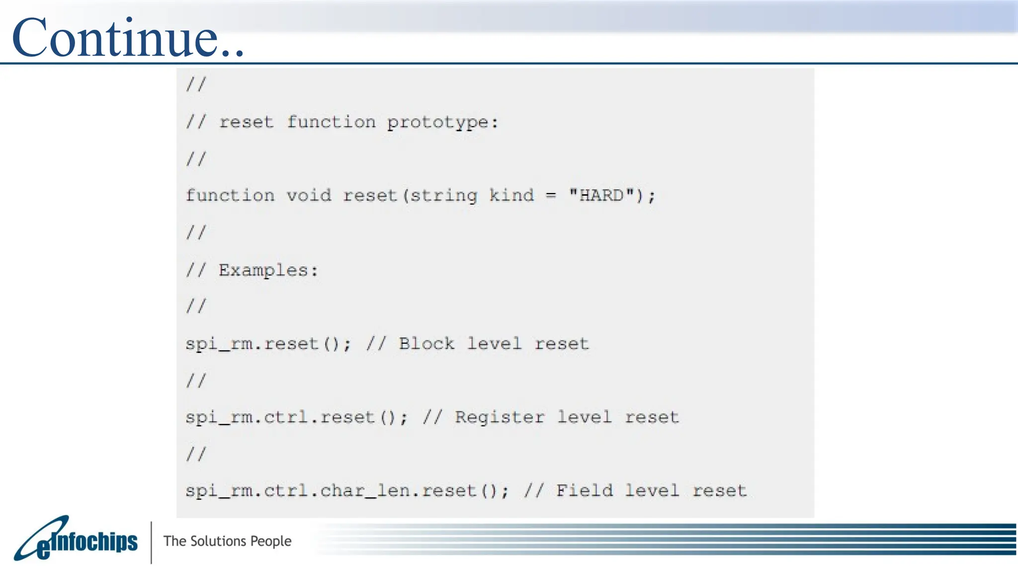
![Reset Method
The reset() method resets the properties of a register field, if
the m_reset[kind] exists.
The default kind is "HARD". If the m_reset[kind] does not exist,
the reset() method does nothing.
Note that the reset() method does not reset a register in the DUT. It only resets
the properties of a register-field object.](https://image.slidesharecdn.com/ralppt-250109175322-3361a874/75/ral_ral_presentation-Ral-introduction-and-detailed-information-39-2048.jpg)