Outline
Code GenerationIssues
Target language Issues
Addresses in Target Code
Basic Blocks and Flow Graphs
Optimizations of Basic Blocks
A Simple Code Generator
Peephole optimization
Register allocation and assignment
Instruction selection by tree rewriting
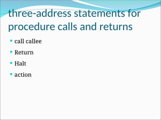
3.
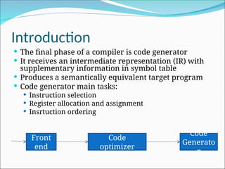
Introduction
The finalphase of a compiler is code generator
It receives an intermediate representation (IR) with
supplementary information in symbol table
Produces a semantically equivalent target program
Code generator main tasks:
Instruction selection
Register allocation and assignment
Insrtuction ordering
Front
end
Code
optimizer
Code
Generato
r
4.
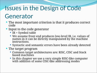
Issues in theDesign of Code
Generator
The most important criterion is that it produces correct
code
Input to the code generator
IR + Symbol table
We assume front end produces low-level IR, i.e. values of
names in it can be directly manipulated by the machine
instructions.
Syntactic and semantic errors have been already detected
The target program
Common target architectures are: RISC, CISC and Stack
based machines
In this chapter we use a very simple RISC-like computer
with addition of some CISC-like addressing modes
5.
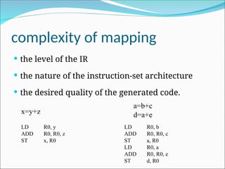
complexity of mapping
the level of the IR
the nature of the instruction-set architecture
the desired quality of the generated code.
x=y+z
LD R0, y
ADD R0, R0, z
ST x, R0
a=b+c
d=a+e
LD R0, b
ADD R0, R0, c
ST a, R0
LD R0, a
ADD R0, R0, e
ST d, R0
6.
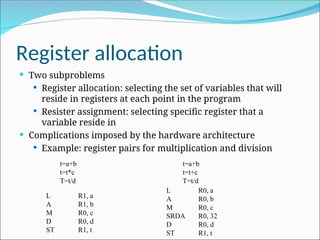
Register allocation
Twosubproblems
Register allocation: selecting the set of variables that will
reside in registers at each point in the program
Resister assignment: selecting specific register that a
variable reside in
Complications imposed by the hardware architecture
Example: register pairs for multiplication and division
t=a+b
t=t*c
T=t/d
t=a+b
t=t+c
T=t/d
L R1, a
A R1, b
M R0, c
D R0, d
ST R1, t
L R0, a
A R0, b
M R0, c
SRDA R0, 32
D R0, d
ST R1, t
7.
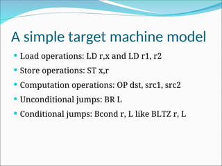
A simple targetmachine model
Load operations: LD r,x and LD r1, r2
Store operations: ST x,r
Computation operations: OP dst, src1, src2
Unconditional jumps: BR L
Conditional jumps: Bcond r, L like BLTZ r, L
8.
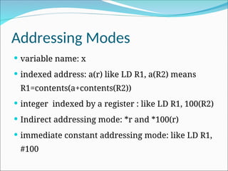
Addressing Modes
variablename: x
indexed address: a(r) like LD R1, a(R2) means
R1=contents(a+contents(R2))
integer indexed by a register : like LD R1, 100(R2)
Indirect addressing mode: *r and *100(r)
immediate constant addressing mode: like LD R1,
#100
9.
b = a[i]
LD R1, i //R1 = i
MUL R1, R1, 8 //R1 = Rl * 8
LD R2, a(R1)
//R2=contents(a+contents(R1))
ST b, R2 //b = R2
10.
a[j] = c
LDR1, c //R1 = c
LD R2, j // R2 = j
MUL R2, R2, 8 //R2 = R2 * 8
ST a(R2), R1 //contents(a+contents(R2))=R1
11.
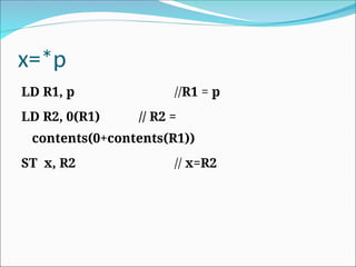
x=*p
LD R1, p//R1 = p
LD R2, 0(R1) // R2 =
contents(0+contents(R1))
ST x, R2 // x=R2
Addresses in theTarget Code
A statically determined area Code
A statically determined data area Static
A dynamically managed area Heap
A dynamically managed area Stack
Basic blocks andflow graphs
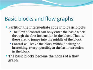
Partition the intermediate code into basic blocks
The flow of control can only enter the basic block
through the first instruction in the block. That is,
there are no jumps into the middle of the block.
Control will leave the block without halting or
branching, except possibly at the last instruction
in the block.
The basic blocks become the nodes of a flow
graph
20.
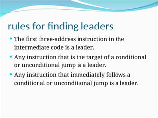
rules for findingleaders
The first three-address instruction in the
intermediate code is a leader.
Any instruction that is the target of a conditional
or unconditional jump is a leader.
Any instruction that immediately follows a
conditional or unconditional jump is a leader.
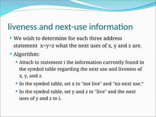
liveness and next-useinformation
We wish to determine for each three address
statement x=y+z what the next uses of x, y and z are.
Algorithm:
Attach to statement i the information currently found in
the symbol table regarding the next use and liveness of
x, y, and z.
In the symbol table, set x to "not live" and "no next use.“
In the symbol table, set y and z to "live" and the next
uses of y and z to i.
24.
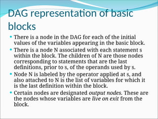
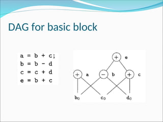
DAG representation ofbasic
blocks
There is a node in the DAG for each of the initial
values of the variables appearing in the basic block.
There is a node N associated with each statement s
within the block. The children of N are those nodes
corresponding to statements that are the last
definitions, prior to s, of the operands used by s.
Node N is labeled by the operator applied at s, and
also attached to N is the list of variables for which it
is the last definition within the block.
Certain nodes are designated output nodes. These are
the nodes whose variables are live on exit from the
block.
25.
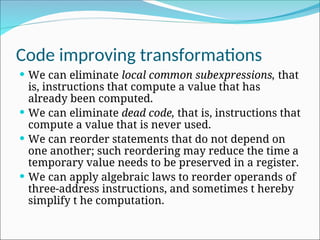
Code improving transformations
We can eliminate local common subexpressions, that
is, instructions that compute a value that has
already been computed.
We can eliminate dead code, that is, instructions that
compute a value that is never used.
We can reorder statements that do not depend on
one another; such reordering may reduce the time a
temporary value needs to be preserved in a register.
We can apply algebraic laws to reorder operands of
three-address instructions, and sometimes t hereby
simplify t he computation.
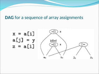
array accesses ina DAG
An assignment from an array, like x = a [i], is represented
by creating a node with operator =[] and two children
representing the initial value of the array, a0 in this case,
and the index i. Variable x becomes a label of this new
node.
An assignment to an array, like a [j] = y, is represented by a
new node with operator []= and three children
representing a0, j and y. There is no variable labeling this
node. What is different is that the creation of this node kills
all currently constructed nodes whose value depends on
a0. A node that has been killed cannot receive any more
labels; that is, it cannot become a common subexpression.
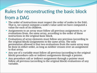
Rules for reconstructingthe basic block
from a DAG
The order of instructions must respect the order of nodes in the DAG.
That is, we cannot compute a node's value until we have computed a
value for each of its children.
Assignments to an array must follow all previous assignments to, or
evaluations from, the same array, according to the order of these
instructions in the original basic block.
Evaluations of array elements must follow any previous (according to
the original block) assignments to the same array. The only
permutation allowed is that two evaluations from the same array may
be done in either order, as long as neither crosses over an assignment
to that array.
Any use of a variable must follow all previous (according to the original
block) procedure calls or indirect assignments through a pointer.
Any procedure call or indirect assignment through a pointer must
follow all previous (according to the original block) evaluations of any
variable.
31.
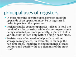
principal uses ofregisters
In most machine architectures, some or all of the
operands of an operation must be in registers in
order to perform the operation.
Registers make good temporaries - places to hold the
result of a subexpression while a larger expression is
being evaluated, or more generally, a place to hold a
variable that is used only within a single basic block.
Registers are often used to help with run-time
storage management, for example, to manage the
run-time stack, including the maintenance of stack
pointers and possibly the top elements of the stack
itself.
32.
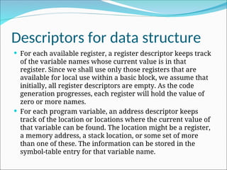
Descriptors for datastructure
For each available register, a register descriptor keeps track
of the variable names whose current value is in that
register. Since we shall use only those registers that are
available for local use within a basic block, we assume that
initially, all register descriptors are empty. As the code
generation progresses, each register will hold the value of
zero or more names.
For each program variable, an address descriptor keeps
track of the location or locations where the current value of
that variable can be found. The location might be a register,
a memory address, a stack location, or some set of more
than one of these. The information can be stored in the
symbol-table entry for that variable name.
33.
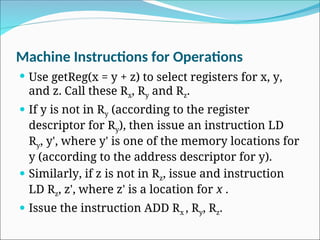
Machine Instructions forOperations
Use getReg(x = y + z) to select registers for x, y,
and z. Call these Rx, Ry and Rz.
If y is not in Ry (according to the register
descriptor for Ry), then issue an instruction LD
Ry, y', where y' is one of the memory locations for
y (according to the address descriptor for y).
Similarly, if z is not in Rz, issue and instruction
LD Rz, z', where z' is a location for x .
Issue the instruction ADD Rx , Ry, Rz.
34.
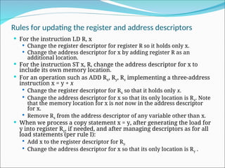
Rules for updatingthe register and address descriptors
For the instruction LD R, x
Change the register descriptor for register R so it holds only x.
Change the address descriptor for x by adding register R as an
additional location.
For the instruction ST x, R, change the address descriptor for x to
include its own memory location.
For an operation such as ADD Rx, Ry, Rz implementing a three-address
instruction x = y + x
Change the register descriptor for Rx so that it holds only x.
Change the address descriptor for x so that its only location is Rx. Note
that the memory location for x is not now in the address descriptor
for x.
Remove Rx from the address descriptor of any variable other than x.
When we process a copy statement x = y, after generating the load for
y into register Ry, if needed, and after managing descriptors as for all
load statements (per rule I):
Add x to the register descriptor for Ry.
Change the address descriptor for x so that its only location is Ry .
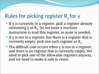
Rules for pickingregister Ry for y
If y is currently in a register, pick a register already
containing y as Ry. Do not issue a machine
instruction to load this register, as none is needed.
If y is not in a register, but there is a register that is
currently empty, pick one such register as Ry.
The difficult case occurs when y is not in a register,
and there is no register that is currently empty. We
need to pick one of the allowable registers anyway,
and we need to make it safe to reuse.
37.
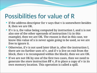
Possibilities for valueof R
If the address descriptor for v says that v is somewhere besides
R, then we are OK.
If v is x, the value being computed by instruction I, and x is not
also one of the other operands of instruction I (z in this
example), then we are OK. The reason is that in this case, we
know this value of x is never again going to be used, so we are
free to ignore it.
Otherwise, if v is not used later (that is, after the instruction I,
there are no further uses of v, and if v is live on exit from the
block, then v is recomputed within the block), then we are OK.
If we are not OK by one of the first two cases, then we need to
generate the store instruction ST v, R to place a copy of v in its
own memory location. This operation is called a spill.
38.
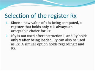
Selection of theregister Rx
1. Since a new value of x is being computed, a
register that holds only x is always an
acceptable choice for Rx.
2. If y is not used after instruction I, and Ry holds
only y after being loaded, Ry can also be used
as Rx. A similar option holds regarding z and
Rx.
39.
Possibilities for valueof R
If the address descriptor for v says that v is somewhere besides
R, then we are OK.
If v is x, the value being computed by instruction I, and x is not
also one of the other operands of instruction I (z in this
example), then we are OK. The reason is that in this case, we
know this value of x is never again going to be used, so we are
free to ignore it.
Otherwise, if v is not used later (that is, after the instruction I,
there are no further uses of v, and if v is live on exit from the
block, then v is recomputed within the block), then we are OK.
If we are not OK by one of the first two cases, then we need to
generate the store instruction ST v, R to place a copy of v in its
own memory location. This operation is called a spill.
40.
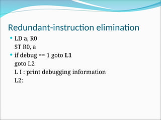
Characteristic of peepholeoptimizations
Redundant-instruction elimination
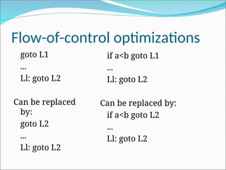
Flow-of-control optimizations
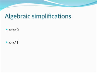
Algebraic simplifications
Use of machine idioms
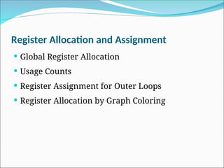
Register Allocation andAssignment
Global Register Allocation
Usage Counts
Register Assignment for Outer Loops
Register Allocation by Graph Coloring
45.
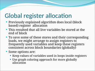
Global register allocation
Previously explained algorithm does local (block
based) register allocation
This resulted that all live variables be stored at the
end of block
To save some of these stores and their corresponding
loads, we might arrange to assign registers to
frequently used variables and keep these registers
consistent across block boundaries (globally)
Some options are:
Keep values of variables used in loops inside registers
Use graph coloring approach for more globally
allocation
46.
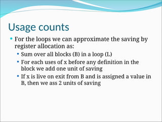
Usage counts
Forthe loops we can approximate the saving by
register allocation as:
Sum over all blocks (B) in a loop (L)
For each uses of x before any definition in the
block we add one unit of saving
If x is live on exit from B and is assigned a value in
B, then we ass 2 units of saving
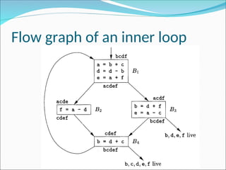
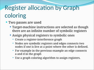
Register allocation byGraph
coloring
Two passes are used
Target-machine instructions are selected as though
there are an infinite number of symbolic registers
Assign physical registers to symbolic ones
Create a register-interference graph
Nodes are symbolic registers and edges connects two
nodes if one is live at a point where the other is defined.
For example in the previous example an edge connects
a and d in the graph
Use a graph coloring algorithm to assign registers.
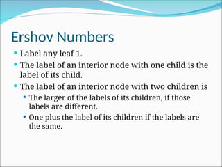
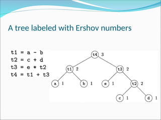
Ershov Numbers
Labelany leaf 1.
The label of an interior node with one child is the
label of its child.
The label of an interior node with two children is
The larger of the labels of its children, if those
labels are different.
One plus the label of its children if the labels are
the same.
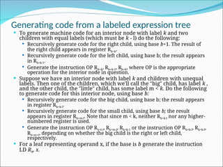
Generating code froma labeled expression tree
To generate machine code for an interior node with label k and two
children with equal labels (which must be k - l) do the following:
Recursively generate code for the right child, using base b+1. The result of
the right child appears in register Rb+k.
Recursively generate code for the left child, using base b; the result appears
in Rb+k-1.
Generate the instruction OP Rb+k, Rb+k-1, Rb+k, where OP is the appropriate
operation for the interior node in question.
Suppose we have an interior node with label k and children with unequal
labels. Then one of the children, which we'll call the "big" child, has label k ,
and the other child, the "little" child, has some label m < k. Do the following
to generate code for this interior node, using base b:
Recursively generate code for the big child, using base b; the result appears
in register Rb+k-l.
Recursively generate code for the small child, using base b; the result
appears in register Rb+m-l. Note that since m < k, neither Rb+k-l nor any higher-
numbered register is used.
Generate the instruction OP Rb+k-l, Rb+m-l, Rb+k-1 or the instruction OP Rb+k-l, Rb+k-l,
Rb+m+l, depending on whether the big child is the right or left child,
respectively.
For a leaf representing operand x, if the base is b generate the instruction
LD Rb, x.
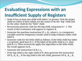
Evaluating Expressions withan
Insufficient Supply of Registers
Node N has at least one child with label r or greater. Pick the larger
child (or either if their labels are the same) to be the "big" child and
let the other child be the "little" child.
Recursively generate code for the big child, using base b = 1. The
result of this evaluation will appear in register Rr
Generate the machine instruction ST tk, Rr, where tk is a temporary
variable used for temporary results used to help evaluate nodes with
label k.
Generate code for the little child as follows. If the little child has label
r or greater, pick base b=1. If the label of the little child is j<r, then
pick b=r-j. Then recursively apply this algorithm to the little child;
the result appears in Rr.
Generate the instruction LD Rr-l, tk.
If the big child is the right child of N, then generate the instruction
OP Rr, Rr, Rr-1. If the big child is the left child, generate OP Rr, Rr-1, Rr.
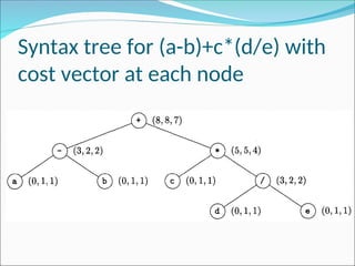
Dynamic Programming Algorithm
Compute bottom-up for each node n of the expression tree
T an array C of costs, in which the ith component C[i] is
the optimal cost of computing the subtree S rooted at n
into a register, assuming i registers are available for the
computation, for
Traverse T, using the cost vectors to determine which
subtrees of T must be computed into memory.
Traverse each tree using the cost vectors and associated
instructions to generate the final target code. The code for
the subtrees computed into memory locations is
generated first.
r
i
1
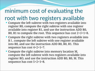
minimum cost ofevaluating the
root with two registers available
Compute the left subtree with two registers available into
register R0, compute the right subtree with one register
available into register R1, and use the instruction ADD R0,
R0, R1 to compute the root. This sequence has cost 2+5+1=8.
Compute the right subtree with two registers available into
R l , compute the left subtree with one register available
into R0, and use the instruction ADD R0, R0, R1. This
sequence has cost 4+2+1=7.
Compute the right subtree into memory location M,
compute the left subtree with two registers available into
register RO, and use the instruction ADD R0, R0, M. This
sequence has cost 5+2+1=8.

![b = a [i]
LD R1, i //R1 = i
MUL R1, R1, 8 //R1 = Rl * 8
LD R2, a(R1)
//R2=contents(a+contents(R1))
ST b, R2 //b = R2](https://image.slidesharecdn.com/chapter8-codegeneration-250824160645-52beb889/85/Chapter-8-1Code-Generation-ppt-for-the-9-320.jpg)
![a[j] = c
LD R1, c //R1 = c
LD R2, j // R2 = j
MUL R2, R2, 8 //R2 = R2 * 8
ST a(R2), R1 //contents(a+contents(R2))=R1](https://image.slidesharecdn.com/chapter8-codegeneration-250824160645-52beb889/85/Chapter-8-1Code-Generation-ppt-for-the-10-320.jpg)


![array accesses in a DAG
An assignment from an array, like x = a [i], is represented
by creating a node with operator =[] and two children
representing the initial value of the array, a0 in this case,
and the index i. Variable x becomes a label of this new
node.
An assignment to an array, like a [j] = y, is represented by a
new node with operator []= and three children
representing a0, j and y. There is no variable labeling this
node. What is different is that the creation of this node kills
all currently constructed nodes whose value depends on
a0. A node that has been killed cannot receive any more
labels; that is, it cannot become a common subexpression.](https://image.slidesharecdn.com/chapter8-codegeneration-250824160645-52beb889/85/Chapter-8-1Code-Generation-ppt-for-the-28-320.jpg)

![Intermediate-code tree for a[i]=b+1](https://image.slidesharecdn.com/chapter8-codegeneration-250824160645-52beb889/85/Chapter-8-1Code-Generation-ppt-for-the-50-320.jpg)
![Dynamic Programming Algorithm
Compute bottom-up for each node n of the expression tree
T an array C of costs, in which the ith component C[i] is
the optimal cost of computing the subtree S rooted at n
into a register, assuming i registers are available for the
computation, for
Traverse T, using the cost vectors to determine which
subtrees of T must be computed into memory.
Traverse each tree using the cost vectors and associated
instructions to generate the final target code. The code for
the subtrees computed into memory locations is
generated first.
r
i
1](https://image.slidesharecdn.com/chapter8-codegeneration-250824160645-52beb889/85/Chapter-8-1Code-Generation-ppt-for-the-60-320.jpg)