Download as PDF, PPTX


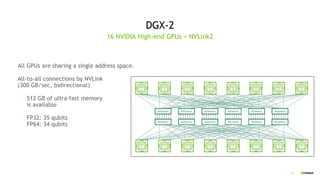


![37
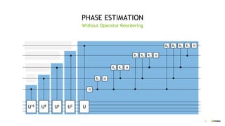
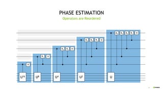
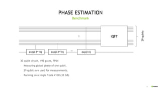
PHASE ESTIMATION
30 qubit circuit, 493 gates, FP64
- Measuring global phase of one qubit.
- 29 qubits are used for measurements.
Operator Reordering, Single GPU
Runtime/ optimization Elapsed time [s] Acceleration
CPU / no optimization 213 1
CPU / optimized 24.7 8.6x
CUDA / no optimization 13.7 15.5x
CUDA / optimized 1.86 114x
exp(i 2n-1q) exp(i 2n-2q) exp(i q)
…
…
29 qubitsiQFT](https://image.slidesharecdn.com/qgate-0-200217002748/85/QGATE-0-3-QUANTUM-CIRCUIT-SIMULATOR-36-320.jpg)

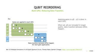
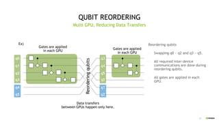
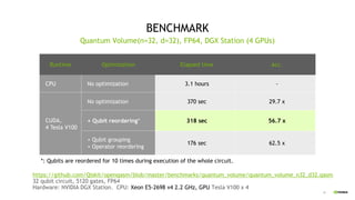
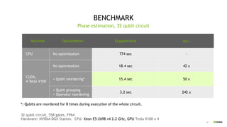


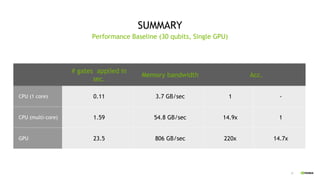
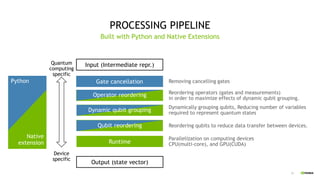
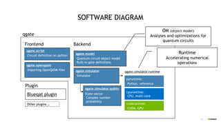
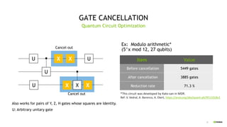
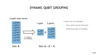
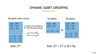
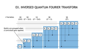
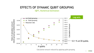
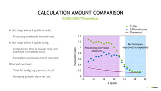
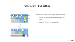
This document discusses QGATE, a quantum circuit simulator that can accelerate simulations using GPUs. QGATE uses several techniques to optimize simulations, including gate cancellation, dynamic qubit grouping, and operator reordering. Gate cancellation removes redundant gates, dynamic qubit grouping reduces the number of variables needed for state vectors when qubits are not entangled, and operator reordering maximizes the effects of dynamic qubit grouping by rearranging gates and measurements. These optimizations aim to improve simulation performance by reducing calculation amounts. Benchmark results show QGATE achieves up to a 220x speedup over CPU simulations for a circuit with 30 qubits and 10 Hadamard gates on each qubit.