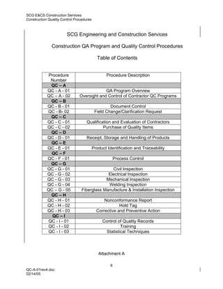
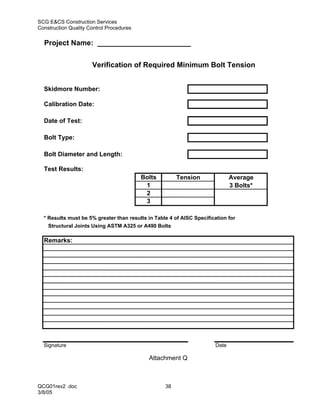
This document provides an overview of the construction quality assurance program for Southern Company Generation Engineering and Construction Services (SCG E&CS) Construction Services. The three main points are:
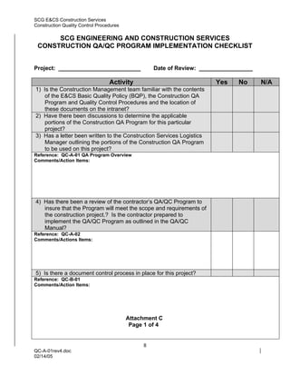
1) The program outlines overall responsibilities, areas to be covered, and criteria for when the program will be invoked on construction jobs.
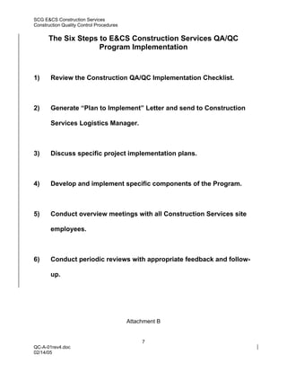
2) Implementation of the program generally follows six steps including reviewing checklists, generating implementation plans, developing specific components, and conducting periodic reviews.
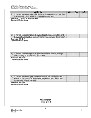
3) The program is intended to meet the requirements of SCG E&CS' Basic Quality Policy and Chapter XII Contract Guidance Manual regarding construction quality assurance. It provides procedures for document control, inspections, nonconformances, and other quality