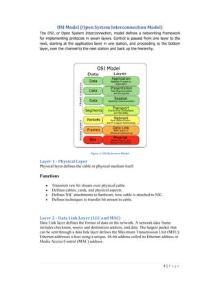
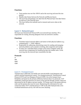
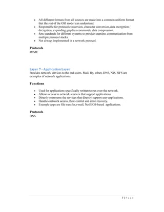
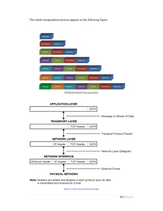
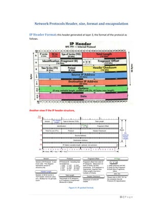
YARMOUK UNIVERSITY 
CS 492: Special Topics 
Preliminaries to Network Monitoring 
Dr. Ahmed Manasrah
Table of Contents 
OSI Model (Open System Interconnection Model) ................................................................... 4 
Layer 1 - Physical Layer .......................................................................................................... 4 
Layer 2 - Data Link Layer (LLC and MAC) ............................................................................... 4 
Functions ........................................................................................................................... 5 
Layer 3 - Network Layer............................................................................................................. 5 
Functions ........................................................................................................................... 5 
Protocols ............................................................................................................................ 5 
Layer 4 - Transport Layer ....................................................................................................... 5 
Functions ........................................................................................................................... 6 
Protocols ............................................................................................................................ 6 
Layer 5 - Session Layer........................................................................................................... 6 
Protocols ................................................................................................................................ 6 
Layer 6 - Presentation Layer .................................................................................................. 6 
Protocols ............................................................................................................................ 7 
Layer 7 - Application Layer .................................................................................................... 7 
Protocols ............................................................................................................................ 7 
Network Communication through OSI: an Example ................................................................. 8 
Network Protocols Header, size, format and encapsulation .................................................. 11 
IP Header Format ................................................................................................................ 11 
TCP Header Format ............................................................................................................. 12 
UDP Header Format ............................................................................................................ 13 
ARP operation and header structure (Format) ................................................................... 13 
ICMP header structure (Format) ......................................................................................... 14 
Ethernet Frame Format ....................................................................................................... 15 
Examples .................................................................................................................................. 16 
IP and ICMP Header format ................................................................................................. 16 
Ethernet and ARP Format .................................................................................................... 17 
2 | P a g e
List of Figures 
Figure 1: OSI Reference Model .................................................................................................. 4 
Figure 2: Network Communication Example (OSI emulation) .................................................. 9 
Figure 3: Data Encapsulation example .................................................................................... 10 
Figure 4. IP packet Format. ...................................................................................................... 11 
Figure 5. The basic structure of a TCP packet ......................................................................... 12 
Figure 6. The basic structure of a UDP packet ........................................................................ 13 
Figure 7. ARP is used to map a device's data-link identifier to its IP address (ARP format) ... 13 
Figure 8. ICMP packet format and Types. ............................................................................... 14 
Figure 9: Ethernet Frame Format ............................................................................................ 15 
Figure 10: IP and ICMP Encapsulation Example ...................................................................... 16 
Figure 11: : Ethernet frame and ARP Encapsulation Example ................................................. 17 
3 | P a g e
OSI Model (Open System Interconnection Model) 
The OSI, or Open System Interconnection, model defines a network 
framework 
for implementing protocols in seven layers. Control is passed from one layer to the 
next, starting at the application layer laye 
in one station, and proceeding to the bottom 
layer, over the channel to the next station and back up the hierarchy. 
Layer 1 - Physical Layer 
Physical layer defines the cable or physical medium itself 
Functions 
networking framewor 
· Transmits raw bit stream over physical cable. 
· Defines cables, cards, and physical aspects. 
· Defines NIC attachments to hardware, how cable is attached to NIC. 
· Defines techniques to transfer bit stream to cable. 
Layer 2 - Data Link Layer (LLC and MAC) 
Data Link layer defines the format of data on the network. A network data frame 
includes checksum, source and destination address, and data. The largest packet that 
can be sent through a data link layer defines 
Ethernet addresses a host using a unique, 48 
Media Access Control (MAC) address. 
4 
Figure 1: OSI Reference Model 
itself. 
ata the Maximum Transmission Unit (MTU). 
48-bit address called its Ethernet address or 
| P a g e
5 | P a g e 
Functions 
· Turns packets into raw bits 100101 and at the receiving end turns bits into 
packets. 
· Handles data frames between the Network and Physical layers. 
· The receiving end packages raw data from the Physical layer into data frames 
for delivery to the Network layer. 
· This layer defines the methods used to transmit and receive data on the 
network. 
Layer 3 - Network Layer 
this layer uses Internetwork Protocol (IP) as its network layer interface. IP is 
responsible for routing, directing datagrams from one network to another. 
Functions 
· Translates logical network address and names to their physical address (e.g. 
computername ==> MAC address). 
· Responsible for addressing, determining routes for sending and managing 
network problems such as packet switching, data congestion and routing. 
· If router can’t send data frame as large as the source computer sends, the 
network layer compensates by breaking the data into smaller units. At the 
receiving end, the network layer reassembles the data. 
Protocols 
IP 
ARP 
RARP 
ICMP 
Layer 4 - Transport Layer 
Transport layer subdivides user-buffer into network-buffer sized datagrams and 
enforces desired transmission control. Two transport protocols, Transmission Control 
Protocol (TCP) and User Datagram Protocol (UDP), sits at the transport layer. 
Reliability and speed are the primary difference between these two protocols. TCP 
establishes connections between two hosts on the network through 'sockets' which are 
determined by the IP address and port number. TCP keeps track of the packet delivery 
order and the packets that must be resent. Maintaining this information for each 
connection makes TCP a stateful protocol. UDP on the other hand provides a low 
overhead transmission service, but with less error checking.
6 | P a g e 
Functions 
· Additional connection below the session layer. 
· Manages the flow control of data between parties across the network. 
· Divides streams of data into chunks or packets; the transport layer of the 
receiving computer reassembles the message from packets. 
· Provides error-checking to guarantee error-free data delivery, with on losses or 
duplications 
· Provides acknowledgment of successful transmissions; requests retransmission 
if some packets don’t arrive error-free. 
· Provides flow control and error-handling. 
Protocols 
TCP 
UDP 
Layer 5 - Session Layer 
The session protocol defines the format of the data sent over the connections. Login 
sessions uses TCP. 
Functions 
· Establishes, maintains and ends sessions across the network. 
· Responsible for name recognition (identification) so only the designated 
parties can participate in the session. 
· Provides synchronization services by planning check points in the data stream 
=> if session fails, only data after the most recent checkpoint need be 
transmitted. 
· Manages who can transmit data at a certain time and for how long. 
· Examples are interactive login and file transfer connections, the session would 
connect and re-connect if there was an interruption; recognize names in 
sessions and register names in history. 
Protocols 
NetBIOS 
Layer 6 - Presentation Layer 
External Data Representation (XDR) sits at the presentation level. It converts local 
representation of data to its canonical form and vice versa. 
Functions 
· Translates from application to network format and vice-versa.
· All different formats from all sources are made into a common uniform format 
7 | P a g e 
that the rest of the OSI model can understand. 
· Responsible for protocol conversion, character conversion,data encryption / 
decryption, expanding graphics commands, data compression. 
· Sets standards for different systems to provide seamless communication from 
multiple protocol stacks. 
· Not always implemented in a network protocol. 
Protocols 
MIME 
Layer 7 - Application Layer 
Provides network services to the end-users. Mail, ftp, telnet, DNS, NIS, NFS are 
examples of network applications. 
Functions 
· Used for applications specifically written to run over the network. 
· Allows access to network services that support applications. 
· Directly represents the services that directly support user applications. 
· Handles network access, flow control and error recovery. 
· Example apps are file transfer,e-mail, NetBIOS-based applications. 
Protocols 
DNS
Network Communication through OSI: an Example 
Assume two networked computers running identical operating systems and 
applications and are using identical protocols (or rules) at all OSI layers. Working in 
conjunction, the applications, the OS, and the hardware implement the seven 
functions described in the OSI model. 
Each computer is also running an e-mail program that is independent of the OSI 
layers. The e-mail program enables the users of the two computers to exchange 
messages. The figure represents the transmission of one message from Sam to 
Charlie. 
The transmission starts when Sam types in a message to Charlie and presses the 
"send" key. Sam's operating system appends to the message (or "encapsulates") a set 
of application-layer instructions (OSI Layer 7) that will be read and executed by the 
application layer on Charlie's computer. The message with its Layer 7 header is then 
transferred to the part of the operating system that deals with presentation issues (OSI 
Layer 6) where a Layer 6 header is appended to the message. The process repeats 
through all the layers until each layer has appended a header. The headers function as 
an escort for the message so that it can successfully negotiate the software and 
hardware in the network and arrive intact at its destination. 
When the data-link-layer header is added at Layer 2, the data unit is known as a 
"frame." The final header, the physical-layer header (OSI Layer 1) tells the hardware 
in Sam's computer the electrical specifics of how the message will be sent (which 
medium, at which voltage, at which speed, etc.). Although it is the final header to be 
added, the Layer 1 header is the first in line when the message travels through the 
medium to the receiving computer. 
When the message with its seven headers arrives at Charlie's computer, the hardware 
in his computer is the first to handle the message. It reads the instructions in the Layer 
1 header, executes them, and strips off the header before passing the message to the 
Layer 2 components. These Layer 2 components execute those instructions, strip off 
the header, and pass the message to Layer 3, and so on. Each layer's header is 
successively stripped off after its instructions have been read so that by the time the 
message arrives at Charlie's e-mail application; the message has been properly 
received, authenticated, decoded, and presented. 
8 | P a g e
9 | P a g e 
Figure 2: Network Communication Example (OSI emulation)
10 | P a g e 
The whole encapsulation process appears as the following figure. 
Figure 3: Data Encapsulation example
Network Protocols Header, size, format and encapsulation 
IP Header Format: this header generated at layer 3, the format of the protocol as 
follows. 
11 | P a g e 
Another view if the IP header structure, 
Figure 4. IP packet Format.
TCP Header Format: this header generated at layer 4, the format of the protocol as 
follows. TCP is a connection oriented protocol that regulates the flow of data. 
12 | P a g e 
Another view if the TCP header structure, 
Figure 5. The basic structure of a TCP packet
UDP Header Format: this header generated at layer 4, the format of the protocol as 
follows. UDP is a connectionless protocol. 
13 | P a g e 
Figure 6. The basic structure of a UDP packet 
ARP operation and header structure (Format) : this protocol is used to map 
the IP address to its MAC address 
Figure 7. ARP is used to map a device's data-link identifier to its IP address (ARP format)
ICMP header structure (Format) : this protocol is used for error reporting 
14 | P a g e 
Figure 8. ICMP packet format and Types.
Ethernet Frame Format: look at this as the content of the data inside the cable. 
15 | P a g e 
Figure 9: Ethernet Frame Format
16 | P a g e 
Examples 
IP and ICMP Header format 
Figure 10: IP and ICMP Encapsulation Example
17 | P a g e 
Ethernet and ARP Format 
Figure 11: : Ethernet frame and ARP Encapsulation Example

Protocols

  • 1.
    YARMOUK UNIVERSITY CS492: Special Topics Preliminaries to Network Monitoring Dr. Ahmed Manasrah
  • 2.
    Table of Contents OSI Model (Open System Interconnection Model) ................................................................... 4 Layer 1 - Physical Layer .......................................................................................................... 4 Layer 2 - Data Link Layer (LLC and MAC) ............................................................................... 4 Functions ........................................................................................................................... 5 Layer 3 - Network Layer............................................................................................................. 5 Functions ........................................................................................................................... 5 Protocols ............................................................................................................................ 5 Layer 4 - Transport Layer ....................................................................................................... 5 Functions ........................................................................................................................... 6 Protocols ............................................................................................................................ 6 Layer 5 - Session Layer........................................................................................................... 6 Protocols ................................................................................................................................ 6 Layer 6 - Presentation Layer .................................................................................................. 6 Protocols ............................................................................................................................ 7 Layer 7 - Application Layer .................................................................................................... 7 Protocols ............................................................................................................................ 7 Network Communication through OSI: an Example ................................................................. 8 Network Protocols Header, size, format and encapsulation .................................................. 11 IP Header Format ................................................................................................................ 11 TCP Header Format ............................................................................................................. 12 UDP Header Format ............................................................................................................ 13 ARP operation and header structure (Format) ................................................................... 13 ICMP header structure (Format) ......................................................................................... 14 Ethernet Frame Format ....................................................................................................... 15 Examples .................................................................................................................................. 16 IP and ICMP Header format ................................................................................................. 16 Ethernet and ARP Format .................................................................................................... 17 2 | P a g e
  • 3.
    List of Figures Figure 1: OSI Reference Model .................................................................................................. 4 Figure 2: Network Communication Example (OSI emulation) .................................................. 9 Figure 3: Data Encapsulation example .................................................................................... 10 Figure 4. IP packet Format. ...................................................................................................... 11 Figure 5. The basic structure of a TCP packet ......................................................................... 12 Figure 6. The basic structure of a UDP packet ........................................................................ 13 Figure 7. ARP is used to map a device's data-link identifier to its IP address (ARP format) ... 13 Figure 8. ICMP packet format and Types. ............................................................................... 14 Figure 9: Ethernet Frame Format ............................................................................................ 15 Figure 10: IP and ICMP Encapsulation Example ...................................................................... 16 Figure 11: : Ethernet frame and ARP Encapsulation Example ................................................. 17 3 | P a g e
  • 4.
    OSI Model (OpenSystem Interconnection Model) The OSI, or Open System Interconnection, model defines a network framework for implementing protocols in seven layers. Control is passed from one layer to the next, starting at the application layer laye in one station, and proceeding to the bottom layer, over the channel to the next station and back up the hierarchy. Layer 1 - Physical Layer Physical layer defines the cable or physical medium itself Functions networking framewor · Transmits raw bit stream over physical cable. · Defines cables, cards, and physical aspects. · Defines NIC attachments to hardware, how cable is attached to NIC. · Defines techniques to transfer bit stream to cable. Layer 2 - Data Link Layer (LLC and MAC) Data Link layer defines the format of data on the network. A network data frame includes checksum, source and destination address, and data. The largest packet that can be sent through a data link layer defines Ethernet addresses a host using a unique, 48 Media Access Control (MAC) address. 4 Figure 1: OSI Reference Model itself. ata the Maximum Transmission Unit (MTU). 48-bit address called its Ethernet address or | P a g e
  • 5.
    5 | Pa g e Functions · Turns packets into raw bits 100101 and at the receiving end turns bits into packets. · Handles data frames between the Network and Physical layers. · The receiving end packages raw data from the Physical layer into data frames for delivery to the Network layer. · This layer defines the methods used to transmit and receive data on the network. Layer 3 - Network Layer this layer uses Internetwork Protocol (IP) as its network layer interface. IP is responsible for routing, directing datagrams from one network to another. Functions · Translates logical network address and names to their physical address (e.g. computername ==> MAC address). · Responsible for addressing, determining routes for sending and managing network problems such as packet switching, data congestion and routing. · If router can’t send data frame as large as the source computer sends, the network layer compensates by breaking the data into smaller units. At the receiving end, the network layer reassembles the data. Protocols IP ARP RARP ICMP Layer 4 - Transport Layer Transport layer subdivides user-buffer into network-buffer sized datagrams and enforces desired transmission control. Two transport protocols, Transmission Control Protocol (TCP) and User Datagram Protocol (UDP), sits at the transport layer. Reliability and speed are the primary difference between these two protocols. TCP establishes connections between two hosts on the network through 'sockets' which are determined by the IP address and port number. TCP keeps track of the packet delivery order and the packets that must be resent. Maintaining this information for each connection makes TCP a stateful protocol. UDP on the other hand provides a low overhead transmission service, but with less error checking.
  • 6.
    6 | Pa g e Functions · Additional connection below the session layer. · Manages the flow control of data between parties across the network. · Divides streams of data into chunks or packets; the transport layer of the receiving computer reassembles the message from packets. · Provides error-checking to guarantee error-free data delivery, with on losses or duplications · Provides acknowledgment of successful transmissions; requests retransmission if some packets don’t arrive error-free. · Provides flow control and error-handling. Protocols TCP UDP Layer 5 - Session Layer The session protocol defines the format of the data sent over the connections. Login sessions uses TCP. Functions · Establishes, maintains and ends sessions across the network. · Responsible for name recognition (identification) so only the designated parties can participate in the session. · Provides synchronization services by planning check points in the data stream => if session fails, only data after the most recent checkpoint need be transmitted. · Manages who can transmit data at a certain time and for how long. · Examples are interactive login and file transfer connections, the session would connect and re-connect if there was an interruption; recognize names in sessions and register names in history. Protocols NetBIOS Layer 6 - Presentation Layer External Data Representation (XDR) sits at the presentation level. It converts local representation of data to its canonical form and vice versa. Functions · Translates from application to network format and vice-versa.
  • 7.
    · All differentformats from all sources are made into a common uniform format 7 | P a g e that the rest of the OSI model can understand. · Responsible for protocol conversion, character conversion,data encryption / decryption, expanding graphics commands, data compression. · Sets standards for different systems to provide seamless communication from multiple protocol stacks. · Not always implemented in a network protocol. Protocols MIME Layer 7 - Application Layer Provides network services to the end-users. Mail, ftp, telnet, DNS, NIS, NFS are examples of network applications. Functions · Used for applications specifically written to run over the network. · Allows access to network services that support applications. · Directly represents the services that directly support user applications. · Handles network access, flow control and error recovery. · Example apps are file transfer,e-mail, NetBIOS-based applications. Protocols DNS
  • 8.
    Network Communication throughOSI: an Example Assume two networked computers running identical operating systems and applications and are using identical protocols (or rules) at all OSI layers. Working in conjunction, the applications, the OS, and the hardware implement the seven functions described in the OSI model. Each computer is also running an e-mail program that is independent of the OSI layers. The e-mail program enables the users of the two computers to exchange messages. The figure represents the transmission of one message from Sam to Charlie. The transmission starts when Sam types in a message to Charlie and presses the "send" key. Sam's operating system appends to the message (or "encapsulates") a set of application-layer instructions (OSI Layer 7) that will be read and executed by the application layer on Charlie's computer. The message with its Layer 7 header is then transferred to the part of the operating system that deals with presentation issues (OSI Layer 6) where a Layer 6 header is appended to the message. The process repeats through all the layers until each layer has appended a header. The headers function as an escort for the message so that it can successfully negotiate the software and hardware in the network and arrive intact at its destination. When the data-link-layer header is added at Layer 2, the data unit is known as a "frame." The final header, the physical-layer header (OSI Layer 1) tells the hardware in Sam's computer the electrical specifics of how the message will be sent (which medium, at which voltage, at which speed, etc.). Although it is the final header to be added, the Layer 1 header is the first in line when the message travels through the medium to the receiving computer. When the message with its seven headers arrives at Charlie's computer, the hardware in his computer is the first to handle the message. It reads the instructions in the Layer 1 header, executes them, and strips off the header before passing the message to the Layer 2 components. These Layer 2 components execute those instructions, strip off the header, and pass the message to Layer 3, and so on. Each layer's header is successively stripped off after its instructions have been read so that by the time the message arrives at Charlie's e-mail application; the message has been properly received, authenticated, decoded, and presented. 8 | P a g e
  • 9.
    9 | Pa g e Figure 2: Network Communication Example (OSI emulation)
  • 10.
    10 | Pa g e The whole encapsulation process appears as the following figure. Figure 3: Data Encapsulation example
  • 11.
    Network Protocols Header,size, format and encapsulation IP Header Format: this header generated at layer 3, the format of the protocol as follows. 11 | P a g e Another view if the IP header structure, Figure 4. IP packet Format.
  • 12.
    TCP Header Format:this header generated at layer 4, the format of the protocol as follows. TCP is a connection oriented protocol that regulates the flow of data. 12 | P a g e Another view if the TCP header structure, Figure 5. The basic structure of a TCP packet
  • 13.
    UDP Header Format:this header generated at layer 4, the format of the protocol as follows. UDP is a connectionless protocol. 13 | P a g e Figure 6. The basic structure of a UDP packet ARP operation and header structure (Format) : this protocol is used to map the IP address to its MAC address Figure 7. ARP is used to map a device's data-link identifier to its IP address (ARP format)
  • 14.
    ICMP header structure(Format) : this protocol is used for error reporting 14 | P a g e Figure 8. ICMP packet format and Types.
  • 15.
    Ethernet Frame Format:look at this as the content of the data inside the cable. 15 | P a g e Figure 9: Ethernet Frame Format
  • 16.
    16 | Pa g e Examples IP and ICMP Header format Figure 10: IP and ICMP Encapsulation Example
  • 17.
    17 | Pa g e Ethernet and ARP Format Figure 11: : Ethernet frame and ARP Encapsulation Example