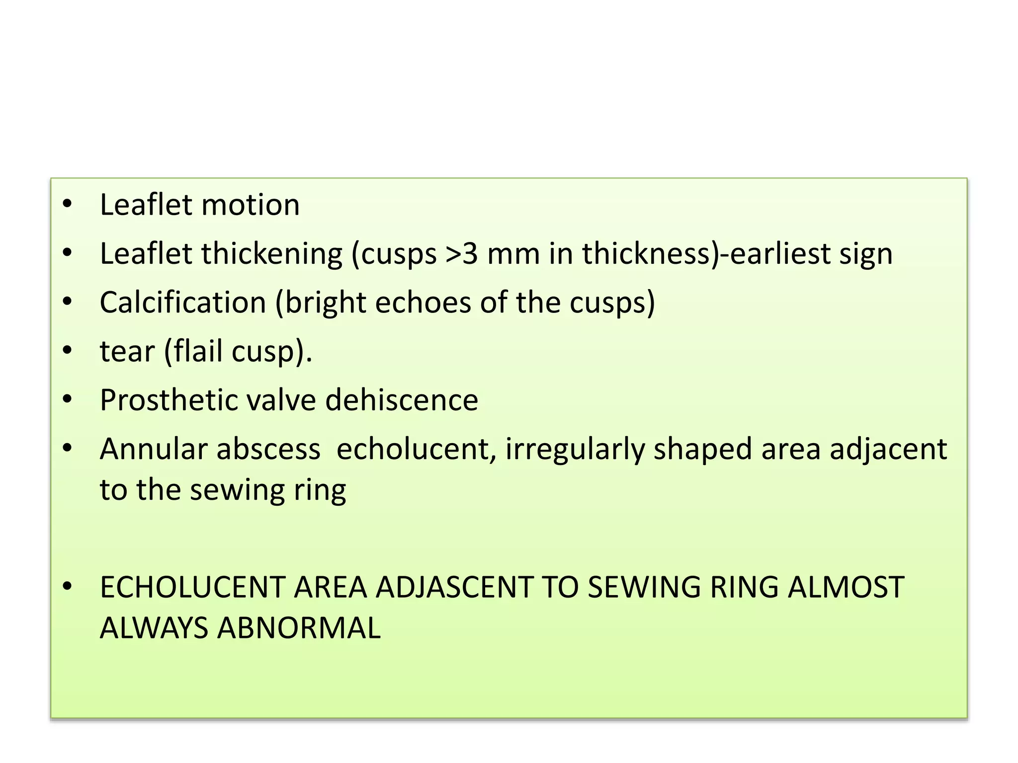
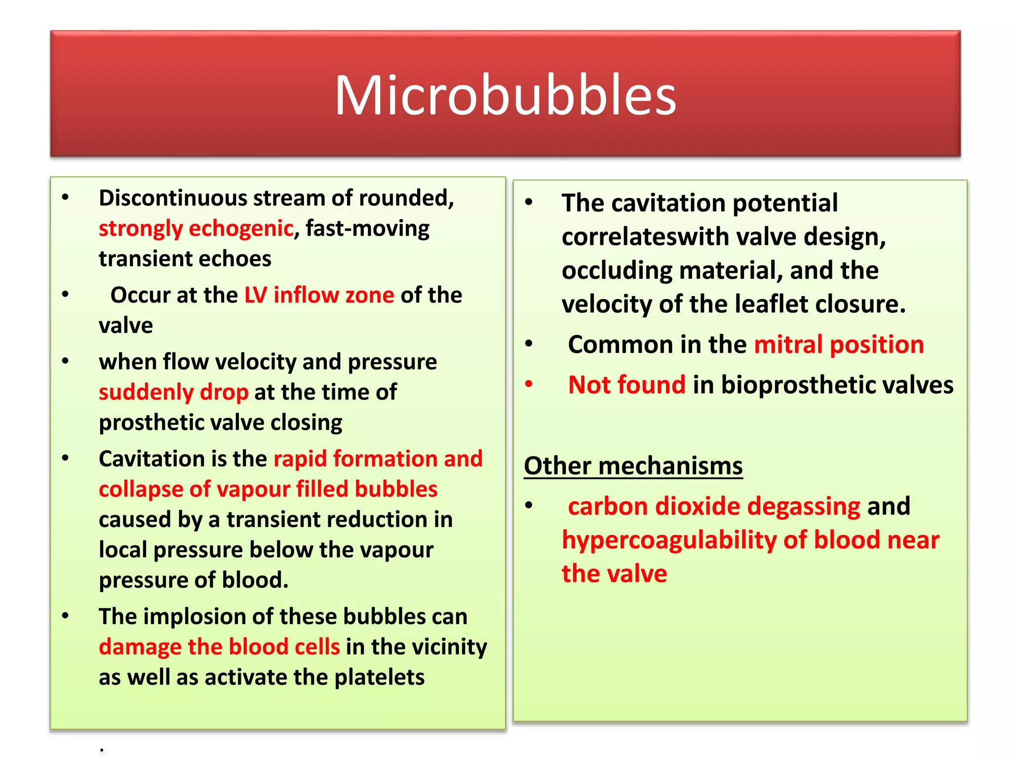
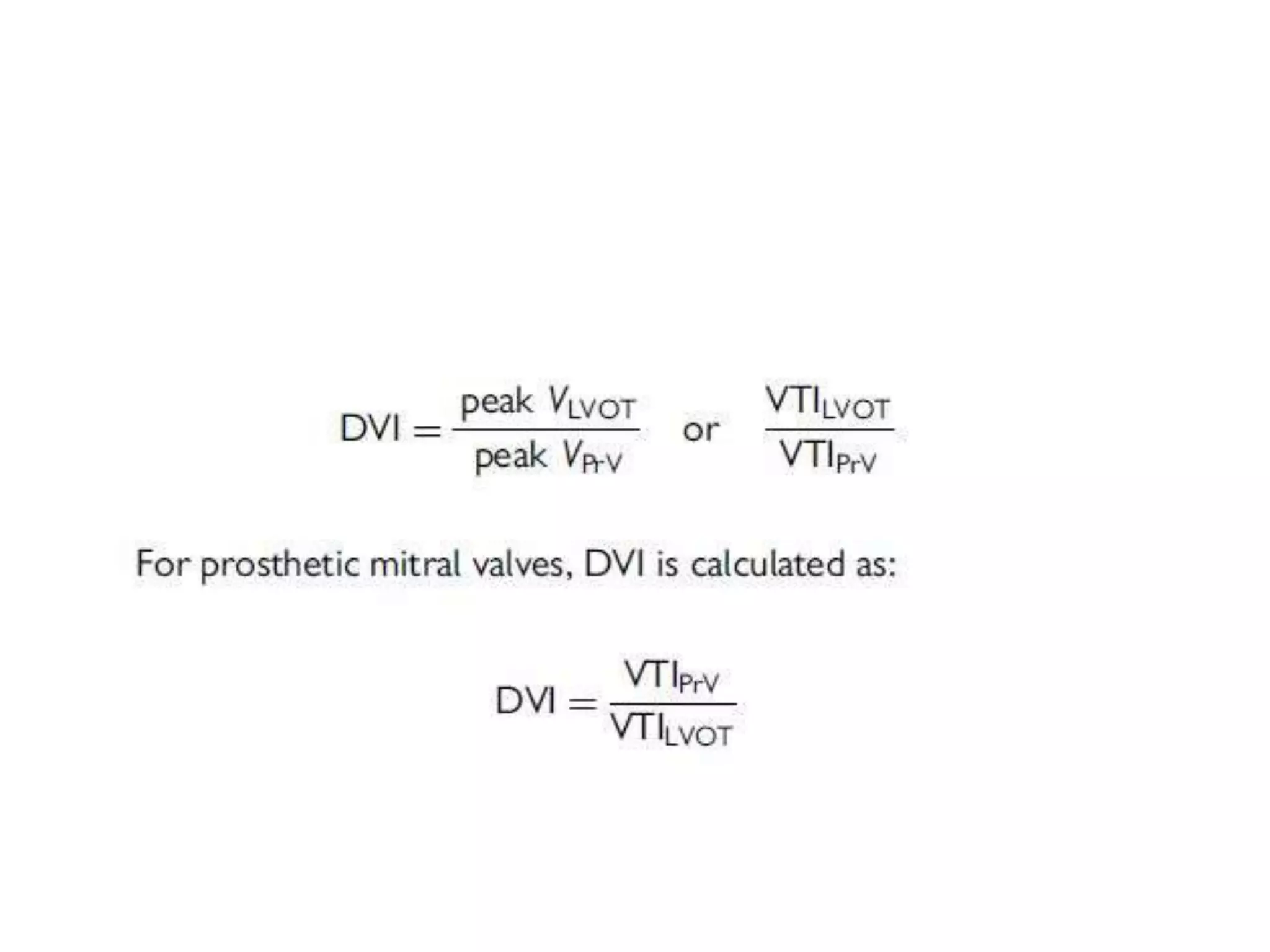
Echocardiographic assessment
• Morphological features
• Hemodynamic characteristics
PRIMARY GOALS OF DOPPLER INTERROGATION
• Assessment of obstruction of prosthetic valve
• Detection and quantification of prosthetic
valve regurgitation
TIMING OF ECHO CARDIOGRAPHIC FOLLOW-UP
• Baseline postoperative TTE study should be performed 3-
12weeks after surgery, when the
• Chest wound has healed
• Ventricular function has improved
• Bioprosthetic valves Annual echocardiography after the first
10 years.
• Mechanical valves routine annual echocardiography is not
indicated in the absence of a change in clinical status
Morphologic and functional characteristics
• Leaflet motion and occluder mobility
• Acoustic shadowing
• Microbubbles
• Spontaneous echo contrast
• Strands
• Leaflet motion
• Leaflet thickening (cusps >3 mm in thickness)-earliest sign
• Calcification (bright echoes of the cusps)
• tear (flail cusp).
• Prosthetic valve dehiscence
• Annular abscess echolucent, irregularly shaped area adjacent
to the sewing ring
• ECHOLUCENT AREA ADJASCENT TO SEWING RING ALMOST
ALWAYS ABNORMAL
Mechanical valve in mitral position
Shadowing
Shadowing
• LA/RA side of a prosthetic mitral/tricuspid valve is obscured
by acoustic shadowing from the TTE
• resulting in a low sensitivity for detection of prosthetic mitral
or tricuspid regurgitation ,thrombus, pannus, or vegetation
• TOE - superior images of the LA/RA side of the mitral/tricuspid
prosthesis
• In the aortic position, the posterior aspect of the valve
appears shadowed on TTE while the anterior aspect of the
valve is shadowed on TOE
ECHO FEATURES OF BILEAFLET VALVE
• Both leaflets are typically visualized .
• Opening angle 750 to 900
• Closing position
1200 for valves ≤25 mm & 1300 for valves ≥27 mm
• Three orifices are seen in diastole with highest
velocity from central orifice
• Bileaflet have the largest EOA of all the mechanical valves (2.4–
3.2 cm2) with little intrinsic mitral regurgitation (MR).
St.jude valve- Echo features
St.jude TTE
St.jude aortic TTE-
Ball and cage-echo
Bioprosthesis -echo features
Microbubbles
• Discontinuous stream of rounded,
strongly echogenic, fast-moving
transient echoes
• Occur at the LV inflow zone of the
valve
• when flow velocity and pressure
suddenly drop at the time of
prosthetic valve closing
• Cavitation is the rapid formation and
collapse of vapour filled bubbles
caused by a transient reduction in
local pressure below the vapour
pressure of blood.
• The implosion of these bubbles can
damage the blood cells in the vicinity
as well as activate the platelets
.
• The cavitation potential
correlateswith valve design,
occluding material, and the
velocity of the leaflet closure.
• Common in the mitral position
• Not found in bioprosthetic valves
Other mechanisms
• carbon dioxide degassing and
hypercoagulability of blood near
the valve
Microbubbles
Strands
• Thin, mildly echogenic, filamentous
• <1 mm thick and >2 mm up to 30 mm length
• move independently from the PHV
• located at the LV inflow side of the PHV (i.e. the atrial side of a
mitral prosthesis or the ventricular side of an aortic
prosthesis).
Strands
Haemodynamic characteristics
• Flow patterns (anterograde flows) and clicks
Quantitative parameters
• Transprosthetic flow velocity and gradients
• Effective orifice area
• Doppler velocity index
• Pressure recovery and localized high gradient
• Physiologic regurgitation (retrograde flows)
Normal flow
Single disc-
large major orifice - dense and lower velocity jet
minor orifice -Higher velocity jet
Bileaflet
dense, lower velocity jet arising from the two lateral orifices
higher velocity jet arising from the central orifice
Ball and cage - blood flows goes around the entire circumference of the
ball and gives two curved side jets and a large jet in the central part
Bioprosthesis - single central anterograde flow
Flow characteristics
Valve type Flow Characteristics
Ball and cage prosthetic valve Much obstruction and little leakage
Tilting disc prosthetic valve Less obstruction and More leakage
Bi leaflet prosthetic valves Less obstruction and More leakage
Bioprostheses Little or no leakage
Homografts, pulmonary autografts, and
unstented bioprosthetic valves
No obstruction to flow
Stented bioprostheses Obstructive to flow
Flow velocity and pressure gradients
• Bernoulli equation, the difference in pressure across a restrictive orifice is
defined as: ΔP=P1−P2=4(V22−V12)
• P1 and V1 are the pressure and velocity, respectively, proximal to the
restrictive orifice
• P2 and V2 are the pressure and velocity, respectively, distal to the orifice
• Peak instantaneous gradient = Peak difference between pressures
• Mean gradient = the average difference.
• Since V2 >> V1 ,the energy balance through the orifice simplifies
to: ΔP=4(V22)
Pitfalls
• In bioprostheses, V2 values may be low (often <2 m/s), so the use of the
simplified Bernoulli equation can cause significant overestimation of
pressure gradients
•
• In these situations, estimation of the pressure gradient is more accurately
determined by integrating the velocity proximal to the prosthesis into the
Bernoulli equation
• Valve size with the small prostheses have higher velocities
• In patients with aortic prostheses and high cardiac output or narrow LV
outflow tract (LVOT), the velocity proximal to the prosthesis may be
elevated.
High gradient across the Prosthetic
heart valve
• Prosthetic valve stenosis or obstruction
• Patient prosthesis mismatch (PPM)
• High flow conditions
• Prosthetic valve regurgitation
• Localised high central jet velocity in bileaflet valves
• Increased heart rate
Underestimation of gradients
1. Failure to align the Doppler
beam parallel with the
highest velocity jet
2. Low flow states
3. Elevated systemic blood
pressure
Overestimation of gradients
1. Mistaking MR flow signal
for transaortic flow signal
(MR starts earlier and lasts
longer than aortic flow)
2. High flow states
3. Pressure recovery
4. Localised high gradient in
central jet
Localised high gradient in central jet(bi leaflet
valve)
Preesure recovery
Pressure recovery phenomenon
• The Aortic Pressure measured by cath Distal to the
orifice Is higher than at the orifice
• Therefore The AoV gradient measured by cath is
LOWER then the the gradient measured by Doppler
Orifice areas
Effective orifice area (EOA)
• EOA not equal to Geo.OA
• EOA = Functional area
• Transvalvular pressure gradients are essentially determined by
the EOA
• EOA corresponds to Vena contracta
• EOA/GOA = Coeefficient of contraction
• Coefficient of contraction varies from 0.90 to 0.71, which may
result in up to a 29% difference between the EOA and GOA.
Effective orifice area
Mitral valve continuity equation
EOA -mitral valve
Prosthetic Heart valve Gradient
calculation.
Equation
• Δ P = 4V2
or
• If LVOT velocity more than 1.5 cm2
Δ P =4 (VPRAV
2 - VLVOT
2)
Limitation of doppler transvalvular Gradient
measurement is that it is FLOW DEPENDENT
Doppler velocity index
Ratio of the proximal flow velocity in the LVOT to the flow
velocity through the aortic prosthesis in aortic PHV
OR
Ratio of flow velocity through the Mitral prosthesis to the flow
velocity across LVOT
Jet contour and acceleration time
Obstructed Aortic PHV
Valve specific approach
Aortic prosthetic valve obstruction
PARAMETERS NORMAL POSSIBLE
OBSTRUCTION
SIGNIFICANT
OBSTRUCTION
QUALITATIVE
VALVE STRUCTURE
AND MOTION
NORMAL ABNORMAL ABNORMAL
TRANSVALVULAR
FLOW CONTOUR
TRIANGULAR
EARLY PEAKING
TRIANGULAR
TO
INTERMEDIATE
ROUNDED
SYMMETRICAL
SEMI
QUANTITATIVE
AT <80 ms 80-100 >100
AT/ET RATIO <0.32 0.32-0.37 >0.37
QUALITATIVE
FLOW
DEPENDENT
PEAK VELOCITY < 3 m/s 3-3.9 >4
MEAN GRADIENT < 20 20-34 >35
FLOW
INDEPENDENT
EOA >1.1 0.8-1.1 <0.8
MEASURED EOA
VS REFERENCE
VALUE
REFERENCE+/- 1
SD
< REFERENCE -1SD <REFERENCE-2SD
DOPPLER
VELOCITY INDEX
>0.35 0.34-0.25 <0.25
Mitral valve obstruction
PARAMETERS NORMAL POSSIBLE
OBSTRUCTION
SIGNIFICANT
OBSTRUCTION
QUALITATIVE
VALVE STRUCTURE
AND MOTION
NORMAL ABNORMAL ABNORMAL
QUANTITATIVE
FLOW DEPENDENT
PEAK VELOCITY < 1.9 m/s 1.9-2.5 >2.5
MEAN GRADIENT < 5 6-10 >10
FLOW
INDEPENDENT
EOA >2 1-2 <1
MEASURED EOA VS
REFERENCE VALUE
REFERENCE+/- 1
SD
< REFERENCE -
1SD
<REFERENCE-2SD
DOPPLER VELOCITY
INDEX
>2.2 2.2-2.5 <2.5
Patient prosthesis mismatch
Adverse effects of PPM
• Less regression of LVH
• Persistent Pulm.HTN
• Decreased exercise capacity
• Lower survival
Ppm in mitral position
Ppm in aortic position
Prosthetic Mitral regurgitation
Qualitative parameters
• Color flow jet areas
• Flow convergence
• Jet density
• Jet contour
• Pulmonary venous flow
• Doppler velocity index
Quantitative parameters
• Vena contarcta width.
• Regurgitant volume.
• Regurgitant fraction.
• EROA.
Paravalvular regurgitation severity
Regurgitant Jet
• <10% of the sewing ring : Mild
• 10- 20 % of the sewing ring : Moderate
• >20% of the sewing ring : Severe
Mitral valve regurgitation
Paravalvular leak -3D ECHO
Aortic valve regurgitation
THROMBUS,PANNUS AND TREATMENT OF
PROSTHETIC VALVE THROMBOSIS
Prosthetic valve thrombosis
Cardiac CT
Pannus
3d echo pannus
Anticoagulation of prosthetic valves
• 1.Target INR
• 2.Antithrombotic therapy
• 3.OAC overdose and bleeding
• 4.Bridging
• 5.Restarting OAC after bleeding event
RISK FACTORS
1.Mitral or Tricuspid valve replacement
2.LVEF <35%
3.Atrial Fibrillation
4.Previous thromboembolism
Anticoagulation "BRIDGING"
Why dabigatran ineffective in prosthetic heart
valves
Take home message
• Types of valves
• Commonly used valves
• Identification of valves in chest xray
• Opening and closing angles in flouroscopy
• Approach to high prosthetic valve gradients
• Prosthetic valve thrombosis
Summary
Summary
Stress Echocardiography
Prosthetic Aortic Valves
• Guide to significant obstruction would be similar to
that for native valves, such as a rise in mean gradient
>15 mm Hg with stress.
Prosthetic Mitral Valves
• Obstruction or PPM is likely if the mean gradient
rises > 18 mm Hg after exercise, even when the
resting mean gradient is normal
MCQ 1
Para valvular regurgitation is said to be severe if regurgitation
is _____% of the sewing ring circumferance?
a) >20%
b) >30%
c) >40%
d) >50%
MCQ 2
Male patient presented with PUO 1 month after Aortic valve
replacement.
What is the echo finding? PLAX & SHORT AXIS images.
MCQ 3
Severe Aortic PPM is defined as
a) Indexed EOA ≤0.65 cm2 /m2
b) Indexed EOA ≤0.85 cm
2
/m
2
c) Indexed EOA ≤1.2 cm
2
/m
2
d) Indexed EOA ≤0.9 cm
2
/m
2
MCQ 4 Identify the valve AND COMPLICATION
Mcq 5 IDENTIFY THE VALVE
THANK YOU

PROSTHETIC_VALVE_ECHO_ASSESSMENT_DR_SANTHOSH_CALICUTcardioSRcom.pptx

  • 1.
    Echocardiographic assessment • Morphologicalfeatures • Hemodynamic characteristics
  • 2.
    PRIMARY GOALS OFDOPPLER INTERROGATION • Assessment of obstruction of prosthetic valve • Detection and quantification of prosthetic valve regurgitation
  • 3.
    TIMING OF ECHOCARDIOGRAPHIC FOLLOW-UP • Baseline postoperative TTE study should be performed 3- 12weeks after surgery, when the • Chest wound has healed • Ventricular function has improved • Bioprosthetic valves Annual echocardiography after the first 10 years. • Mechanical valves routine annual echocardiography is not indicated in the absence of a change in clinical status
  • 4.
    Morphologic and functionalcharacteristics • Leaflet motion and occluder mobility • Acoustic shadowing • Microbubbles • Spontaneous echo contrast • Strands
  • 5.
    • Leaflet motion •Leaflet thickening (cusps >3 mm in thickness)-earliest sign • Calcification (bright echoes of the cusps) • tear (flail cusp). • Prosthetic valve dehiscence • Annular abscess echolucent, irregularly shaped area adjacent to the sewing ring • ECHOLUCENT AREA ADJASCENT TO SEWING RING ALMOST ALWAYS ABNORMAL
  • 6.
    Mechanical valve inmitral position
  • 7.
  • 8.
    Shadowing • LA/RA sideof a prosthetic mitral/tricuspid valve is obscured by acoustic shadowing from the TTE • resulting in a low sensitivity for detection of prosthetic mitral or tricuspid regurgitation ,thrombus, pannus, or vegetation • TOE - superior images of the LA/RA side of the mitral/tricuspid prosthesis • In the aortic position, the posterior aspect of the valve appears shadowed on TTE while the anterior aspect of the valve is shadowed on TOE
  • 9.
    ECHO FEATURES OFBILEAFLET VALVE • Both leaflets are typically visualized . • Opening angle 750 to 900 • Closing position 1200 for valves ≤25 mm & 1300 for valves ≥27 mm • Three orifices are seen in diastole with highest velocity from central orifice • Bileaflet have the largest EOA of all the mechanical valves (2.4– 3.2 cm2) with little intrinsic mitral regurgitation (MR).
  • 10.
  • 11.
  • 12.
  • 13.
  • 14.
  • 15.
    Microbubbles • Discontinuous streamof rounded, strongly echogenic, fast-moving transient echoes • Occur at the LV inflow zone of the valve • when flow velocity and pressure suddenly drop at the time of prosthetic valve closing • Cavitation is the rapid formation and collapse of vapour filled bubbles caused by a transient reduction in local pressure below the vapour pressure of blood. • The implosion of these bubbles can damage the blood cells in the vicinity as well as activate the platelets . • The cavitation potential correlateswith valve design, occluding material, and the velocity of the leaflet closure. • Common in the mitral position • Not found in bioprosthetic valves Other mechanisms • carbon dioxide degassing and hypercoagulability of blood near the valve
  • 17.
  • 18.
    Strands • Thin, mildlyechogenic, filamentous • <1 mm thick and >2 mm up to 30 mm length • move independently from the PHV • located at the LV inflow side of the PHV (i.e. the atrial side of a mitral prosthesis or the ventricular side of an aortic prosthesis).
  • 19.
  • 20.
    Haemodynamic characteristics • Flowpatterns (anterograde flows) and clicks Quantitative parameters • Transprosthetic flow velocity and gradients • Effective orifice area • Doppler velocity index • Pressure recovery and localized high gradient • Physiologic regurgitation (retrograde flows)
  • 21.
    Normal flow Single disc- largemajor orifice - dense and lower velocity jet minor orifice -Higher velocity jet Bileaflet dense, lower velocity jet arising from the two lateral orifices higher velocity jet arising from the central orifice Ball and cage - blood flows goes around the entire circumference of the ball and gives two curved side jets and a large jet in the central part Bioprosthesis - single central anterograde flow
  • 24.
    Flow characteristics Valve typeFlow Characteristics Ball and cage prosthetic valve Much obstruction and little leakage Tilting disc prosthetic valve Less obstruction and More leakage Bi leaflet prosthetic valves Less obstruction and More leakage Bioprostheses Little or no leakage Homografts, pulmonary autografts, and unstented bioprosthetic valves No obstruction to flow Stented bioprostheses Obstructive to flow
  • 25.
    Flow velocity andpressure gradients • Bernoulli equation, the difference in pressure across a restrictive orifice is defined as: ΔP=P1−P2=4(V22−V12) • P1 and V1 are the pressure and velocity, respectively, proximal to the restrictive orifice • P2 and V2 are the pressure and velocity, respectively, distal to the orifice • Peak instantaneous gradient = Peak difference between pressures • Mean gradient = the average difference. • Since V2 >> V1 ,the energy balance through the orifice simplifies to: ΔP=4(V22)
  • 26.
    Pitfalls • In bioprostheses,V2 values may be low (often <2 m/s), so the use of the simplified Bernoulli equation can cause significant overestimation of pressure gradients • • In these situations, estimation of the pressure gradient is more accurately determined by integrating the velocity proximal to the prosthesis into the Bernoulli equation • Valve size with the small prostheses have higher velocities • In patients with aortic prostheses and high cardiac output or narrow LV outflow tract (LVOT), the velocity proximal to the prosthesis may be elevated.
  • 27.
    High gradient acrossthe Prosthetic heart valve • Prosthetic valve stenosis or obstruction • Patient prosthesis mismatch (PPM) • High flow conditions • Prosthetic valve regurgitation • Localised high central jet velocity in bileaflet valves • Increased heart rate
  • 28.
    Underestimation of gradients 1.Failure to align the Doppler beam parallel with the highest velocity jet 2. Low flow states 3. Elevated systemic blood pressure Overestimation of gradients 1. Mistaking MR flow signal for transaortic flow signal (MR starts earlier and lasts longer than aortic flow) 2. High flow states 3. Pressure recovery 4. Localised high gradient in central jet
  • 29.
    Localised high gradientin central jet(bi leaflet valve)
  • 31.
  • 32.
    Pressure recovery phenomenon •The Aortic Pressure measured by cath Distal to the orifice Is higher than at the orifice • Therefore The AoV gradient measured by cath is LOWER then the the gradient measured by Doppler
  • 33.
  • 34.
    Effective orifice area(EOA) • EOA not equal to Geo.OA • EOA = Functional area • Transvalvular pressure gradients are essentially determined by the EOA • EOA corresponds to Vena contracta • EOA/GOA = Coeefficient of contraction • Coefficient of contraction varies from 0.90 to 0.71, which may result in up to a 29% difference between the EOA and GOA.
  • 37.
  • 39.
  • 40.
  • 42.
    Prosthetic Heart valveGradient calculation. Equation • Δ P = 4V2 or • If LVOT velocity more than 1.5 cm2 Δ P =4 (VPRAV 2 - VLVOT 2) Limitation of doppler transvalvular Gradient measurement is that it is FLOW DEPENDENT
  • 43.
    Doppler velocity index Ratioof the proximal flow velocity in the LVOT to the flow velocity through the aortic prosthesis in aortic PHV OR Ratio of flow velocity through the Mitral prosthesis to the flow velocity across LVOT
  • 46.
    Jet contour andacceleration time
  • 47.
  • 48.
  • 49.
    Aortic prosthetic valveobstruction PARAMETERS NORMAL POSSIBLE OBSTRUCTION SIGNIFICANT OBSTRUCTION QUALITATIVE VALVE STRUCTURE AND MOTION NORMAL ABNORMAL ABNORMAL TRANSVALVULAR FLOW CONTOUR TRIANGULAR EARLY PEAKING TRIANGULAR TO INTERMEDIATE ROUNDED SYMMETRICAL SEMI QUANTITATIVE AT <80 ms 80-100 >100 AT/ET RATIO <0.32 0.32-0.37 >0.37
  • 50.
    QUALITATIVE FLOW DEPENDENT PEAK VELOCITY <3 m/s 3-3.9 >4 MEAN GRADIENT < 20 20-34 >35 FLOW INDEPENDENT EOA >1.1 0.8-1.1 <0.8 MEASURED EOA VS REFERENCE VALUE REFERENCE+/- 1 SD < REFERENCE -1SD <REFERENCE-2SD DOPPLER VELOCITY INDEX >0.35 0.34-0.25 <0.25
  • 52.
    Mitral valve obstruction PARAMETERSNORMAL POSSIBLE OBSTRUCTION SIGNIFICANT OBSTRUCTION QUALITATIVE VALVE STRUCTURE AND MOTION NORMAL ABNORMAL ABNORMAL QUANTITATIVE FLOW DEPENDENT PEAK VELOCITY < 1.9 m/s 1.9-2.5 >2.5 MEAN GRADIENT < 5 6-10 >10 FLOW INDEPENDENT EOA >2 1-2 <1 MEASURED EOA VS REFERENCE VALUE REFERENCE+/- 1 SD < REFERENCE - 1SD <REFERENCE-2SD DOPPLER VELOCITY INDEX >2.2 2.2-2.5 <2.5
  • 54.
  • 55.
    Adverse effects ofPPM • Less regression of LVH • Persistent Pulm.HTN • Decreased exercise capacity • Lower survival
  • 56.
    Ppm in mitralposition
  • 57.
    Ppm in aorticposition
  • 58.
    Prosthetic Mitral regurgitation Qualitativeparameters • Color flow jet areas • Flow convergence • Jet density • Jet contour • Pulmonary venous flow • Doppler velocity index Quantitative parameters • Vena contarcta width. • Regurgitant volume. • Regurgitant fraction. • EROA.
  • 59.
    Paravalvular regurgitation severity RegurgitantJet • <10% of the sewing ring : Mild • 10- 20 % of the sewing ring : Moderate • >20% of the sewing ring : Severe
  • 60.
  • 63.
  • 64.
  • 65.
    THROMBUS,PANNUS AND TREATMENTOF PROSTHETIC VALVE THROMBOSIS
  • 67.
  • 69.
  • 71.
  • 72.
  • 73.
    Anticoagulation of prostheticvalves • 1.Target INR • 2.Antithrombotic therapy • 3.OAC overdose and bleeding • 4.Bridging • 5.Restarting OAC after bleeding event
  • 74.
    RISK FACTORS 1.Mitral orTricuspid valve replacement 2.LVEF <35% 3.Atrial Fibrillation 4.Previous thromboembolism
  • 80.
  • 81.
    Why dabigatran ineffectivein prosthetic heart valves
  • 87.
    Take home message •Types of valves • Commonly used valves • Identification of valves in chest xray • Opening and closing angles in flouroscopy • Approach to high prosthetic valve gradients • Prosthetic valve thrombosis
  • 88.
  • 89.
  • 91.
    Stress Echocardiography Prosthetic AorticValves • Guide to significant obstruction would be similar to that for native valves, such as a rise in mean gradient >15 mm Hg with stress. Prosthetic Mitral Valves • Obstruction or PPM is likely if the mean gradient rises > 18 mm Hg after exercise, even when the resting mean gradient is normal
  • 92.
    MCQ 1 Para valvularregurgitation is said to be severe if regurgitation is _____% of the sewing ring circumferance? a) >20% b) >30% c) >40% d) >50%
  • 93.
    MCQ 2 Male patientpresented with PUO 1 month after Aortic valve replacement. What is the echo finding? PLAX & SHORT AXIS images.
  • 94.
    MCQ 3 Severe AorticPPM is defined as a) Indexed EOA ≤0.65 cm2 /m2 b) Indexed EOA ≤0.85 cm 2 /m 2 c) Indexed EOA ≤1.2 cm 2 /m 2 d) Indexed EOA ≤0.9 cm 2 /m 2
  • 96.
    MCQ 4 Identifythe valve AND COMPLICATION
  • 97.
    Mcq 5 IDENTIFYTHE VALVE
  • 98.