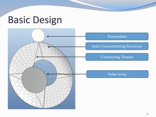
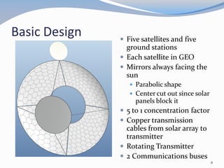
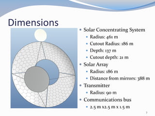
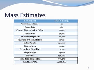
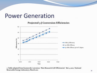
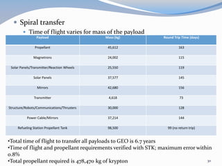
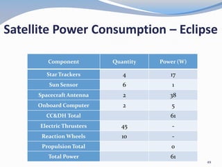
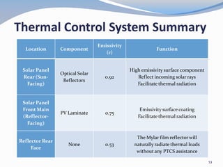
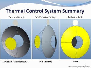
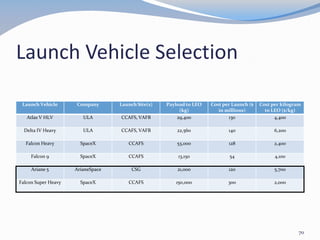
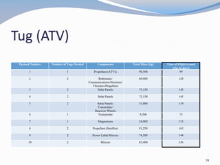
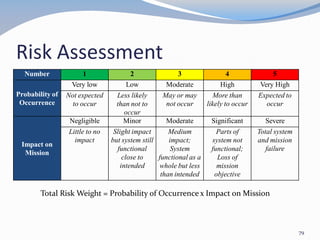
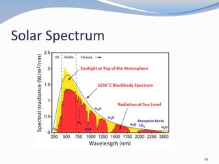
The document summarizes the design of a space-based solar power system. It proposes using five satellites in geosynchronous orbit to collect and transmit solar power to five ground stations via microwave beams. Each satellite would have a large solar concentrating structure and transmitter to beam 1 GW of power to Earth. The design aims to meet requirements to transmit 1 GW of power by 2040 for under $21 billion.

![Outer Rim (Green)
Inner Rim (Purple)
Backbone Segments (Red)
Connecting Trusses (Blue)
Solar Array Frame (Black)
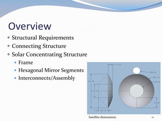
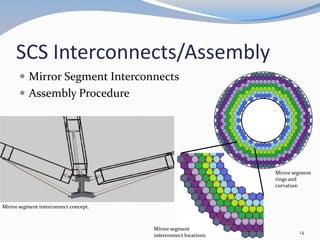
SCS Frame/Connecting Structure
Outer and Inner Rims
Backbone
Connecting Structure
ATK SRTM deployed [3.1].
12
Structural Components](https://image.slidesharecdn.com/fdrpresentation-180120131103/85/Senior-Design-Project-Space-Based-Solar-Power-System-12-320.jpg)
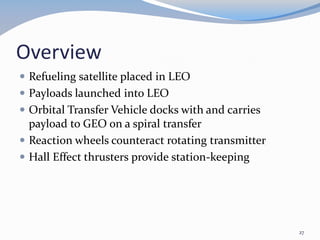
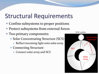
![Station-Keeping
Maneuver Burn Time Delta-V per burn
De-spin reaction wheels 47.3 minutes every 52.1
days
0.0109 m/s
E-W station-keeping 56 minutes, twice per day
at 6AM and 6PM
0.14 m/s
E-W station-keeping 5.7 minutes at midnight
every 60 days
0.006 m/s
N-S station-keeping 16 hours at 6AM every 60
days
2.5 m/s
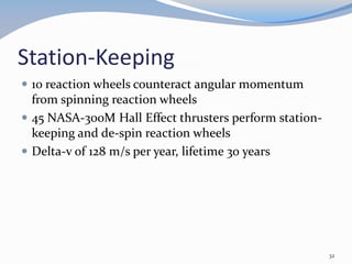
•Station-keeping propellant mass is 57,770 kg per satellite
•Thrusters magnetically shielded to greatly reduce erosion (approx. 600 times
less) [4.1]
•Each satellite will carry 60,000 kg of propellant for station-keeping during
construction
34](https://image.slidesharecdn.com/fdrpresentation-180120131103/85/Senior-Design-Project-Space-Based-Solar-Power-System-34-320.jpg)
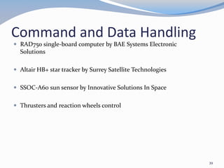
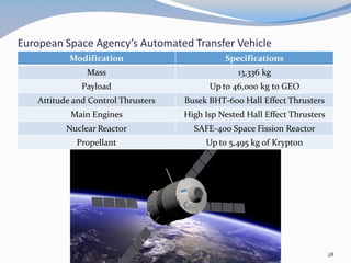
![Communications
Spacecraft antenna
2.4 m diameter parabolic
reflector offset feed by Av
Comm
deployable
• Ground station
antenna
– 2.4 m diameter parabolic
reflector offset feed by
Skyware Global
[5.2][5.1]
41](https://image.slidesharecdn.com/fdrpresentation-180120131103/85/Senior-Design-Project-Space-Based-Solar-Power-System-41-320.jpg)
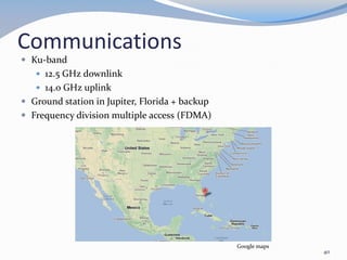
![ATV communication
Modified ATV as orbit transfer tug
NASA TDRSS network for continuous communication
44
[5.3]](https://image.slidesharecdn.com/fdrpresentation-180120131103/85/Senior-Design-Project-Space-Based-Solar-Power-System-44-320.jpg)
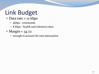
![Rectenna Elements
Serrated Panel
Ground Plane Mesh
Dipole Foreplane
Depiction of diode foreplane [7.1]
58](https://image.slidesharecdn.com/fdrpresentation-180120131103/85/Senior-Design-Project-Space-Based-Solar-Power-System-58-320.jpg)
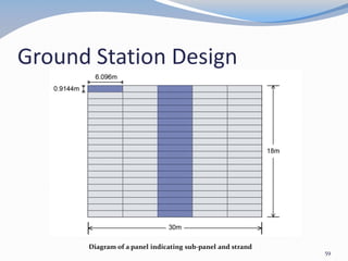
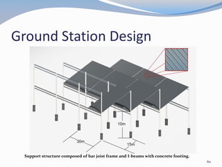
![Ground Station Design Cont.
Visualization of a ground power receiving station [7.2]
61](https://image.slidesharecdn.com/fdrpresentation-180120131103/85/Senior-Design-Project-Space-Based-Solar-Power-System-61-320.jpg)
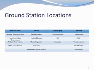
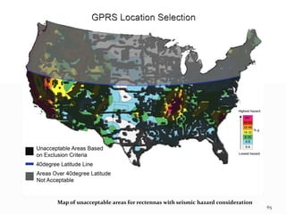
![Map of unacceptable areas for rectennas [7.3]
63](https://image.slidesharecdn.com/fdrpresentation-180120131103/85/Senior-Design-Project-Space-Based-Solar-Power-System-63-320.jpg)
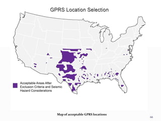
![Map of unacceptable areas for rectennas including 40º latitude [7.3]
64](https://image.slidesharecdn.com/fdrpresentation-180120131103/85/Senior-Design-Project-Space-Based-Solar-Power-System-64-320.jpg)
![Selected GPRS Locations and existing power plants and power lines [7.3]
67](https://image.slidesharecdn.com/fdrpresentation-180120131103/85/Senior-Design-Project-Space-Based-Solar-Power-System-67-320.jpg)
![ATV Docking
Used on current ATV
Equipped with guidance
system to direct ADA
into PDA
ATV has ADA
Refueling satellite has 5
PDAs
Payload containers have
ADA and PDA (one on
each end)
3rd IAASS Conference - 4 -
“Building a safer space together”
ATV to ISS docking using th
ISS docking
port: PDA
ATV Docking
system: ADA
cone
socket
Grooves &
Latch stops
Probe
head
latches
Docking system [8.9]
75](https://image.slidesharecdn.com/fdrpresentation-180120131103/85/Senior-Design-Project-Space-Based-Solar-Power-System-75-320.jpg)

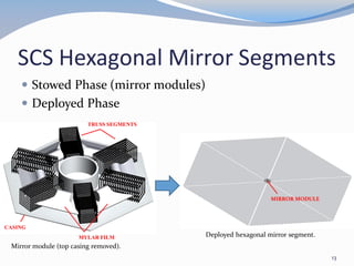
![85
Truss
Axial Strength
(N)
Column Length
(m)
Mass per
Length (kg/m)
Truss Radius
(m)
Deployment
Method
ILC Dover
UltraBoom
1413 9.06 0.1445 0.09 Inflatable
L’Garde SSP
truss
2473 78.28 0.7 0.68 Thermoset
ATK GR1 494 40.30 0.07 0.197 Uncoiled
ATK SRTM 5270 60 3.835 0.561 Articulating
Deployable Truss Comparison [3.2]
Thin-Film Comparison [3.3]
Thin Film
Density
(kg/m3)
Tensile
Strength
(MPa)
Thickness
(µm)
Kapton 1,420 138 12.7
CP1 1,434 99.97 25.4
Mylar 1,390 179.3 12.2](https://image.slidesharecdn.com/fdrpresentation-180120131103/85/Senior-Design-Project-Space-Based-Solar-Power-System-85-320.jpg)
![ATV Appendix
High Isp NHT engine (per unit) [4.2] Isp: 5000s
Thrust: 6.1 N
Efficiency: 65%
Power consumption: 200 kW
Mass: 280 kg
Busek BHT-600 thruster (per unit) [4.3] Isp: 1585 s
Thrust: 42 mN
Efficiency: 49%
Power consumption: 600 W
SAFE-400 Fission Reactor (per unit) [4.4] 400 kWt
200 kWe
540 kg
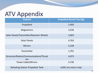
Krypton Propellant ATV Maximum 5,495 kg
94](https://image.slidesharecdn.com/fdrpresentation-180120131103/85/Senior-Design-Project-Space-Based-Solar-Power-System-94-320.jpg)
![Refueling Satellite Appendix
5 Titanium 6Al-4V fuel tanks 2 mm thick, interior volume
530 m3 carry 96,000 kg krypton each
Spacecraft bus is pentagonal prism with a PDA on all 5
sides for propellant tanks to dock with
Tanks will be coated with optical solar reflectors to keep
maximum temperature at 150 K
Orientation will remain in the plane of the ecliptic to
minimize surface area exposed to the Sun
Busek BHT-1000 [4.3] Isp: 1,750s
Thrust: 58 N
Power consumption: 1 kW
Mass: ~5 kg
97](https://image.slidesharecdn.com/fdrpresentation-180120131103/85/Senior-Design-Project-Space-Based-Solar-Power-System-97-320.jpg)
![Station-Keeping Appendix
NASA-300M thrusters [4.5] Isp: 3,220s
Thrust: 1.13 N
Efficiency: 63%
Power consumption: 20 kW
Mass: ~15 kg
Reaction Wheels Aluminum
0.75 m radius
0.23 m height
3,500 RPM
98](https://image.slidesharecdn.com/fdrpresentation-180120131103/85/Senior-Design-Project-Space-Based-Solar-Power-System-98-320.jpg)
![References
[3.1] “Articulated Mast Systems,” ATK, [http://www.atk.com/wp-
content/uploads/2012/09/ADAM-2011.pdf. Accessed 2/12/13.]
99](https://image.slidesharecdn.com/fdrpresentation-180120131103/85/Senior-Design-Project-Space-Based-Solar-Power-System-99-320.jpg)
![References
[4.1] Mikellides, Ioannis G., Katz, Ira, Hofer, Richard R., and Goebel,
Dan M., “Magnetic shielding of walls from the unmagnetized ion beam
in a Hall thruster”, Applied Physics Letters, Jan 2013.
[4.2] Space Mission Analysis and Design, Microcosm Press, CA, pp 560.
[4.3] “Low Power Hall Effect Thrusters”, Busek, 2012.
[http://www.busek.com/index_htm_files/70008510_revA.pdf. Accessed
02/15/2013].
[4.4] Poston, David I., Kapernick, Richard J., and Guffee, Ray M.,
“Design and Analysis of the SAFE-400 Space Fission Reactor”, AIP
Conference.
[4.5] Kamhawi, Hani, Haag, Thomas W., Jacobsen, David T., and
Manzella, David H., “Performance Evaluation of the NASA-300M
20kW Hall Effect Thruster”, 47th AIAA/ASME/SAE/ASEE Joint
Propulsion Conference and Exhibit, Aug. 2011.
100](https://image.slidesharecdn.com/fdrpresentation-180120131103/85/Senior-Design-Project-Space-Based-Solar-Power-System-100-320.jpg)
![References
[5.1] http://avcomm.com.au/index.php/Auto-Deploy-Antenna-
Systems/Oyster-85-Auto-Deploy-Satellite-Television-System/flypage-
sparkstore.tpl.html
[5.2] Skyware Global. 2.4 m Ku-band RxTx Class III Antenna System.
2012
[5.3]https://www.spacecomm.nasa.gov/spacecomm//programs/tdrss/s
ystem_description.cfm
101](https://image.slidesharecdn.com/fdrpresentation-180120131103/85/Senior-Design-Project-Space-Based-Solar-Power-System-101-320.jpg)
![References
[7.1] “Satellite Power System,” DOE/NASA Concept Development and
Evaluation Program, DOE/ER-0023, Oct. 1978.
[7.2] “Cutting the cord: ISTF-07.” Mainland High School ISTF. 2007.
[http://mainland.cctt.org/istf2008/rectennas.asp Accessed 1/19/13.]
[7.3] Blackburn, J. B., Bavinger, B. A., “Satellite Power System (SPS)
Mapping of Exclusion Areas for Rectenna Sites,” DOE/NASA Concept
Development and Evaluation Program, HCP/R-4024-10, Oct. 1978.
102](https://image.slidesharecdn.com/fdrpresentation-180120131103/85/Senior-Design-Project-Space-Based-Solar-Power-System-102-320.jpg)
![References
[8.1] Arianespace, “Ariane 5 User’s Manual, Issue 5 Revision 1,” Arianespace, Washington, DC, July 2011.
[8.2] Wertz, R. J., Everett, D. F., and Puschell, J. J. (eds.), Space Mission Engineering: The New SMAD, Microcosm Press, Hawthorne,
CA, 2011, pp. 859, 862.
[8.3] United Launch Alliance, “Atlas V Launch Services User’s Guide, Revison 11,” United Launch Alliance, Littleton, CO, March 2010.
[8.4] United Launch Alliance, “Delta IV Payload Planners Guide,” United Launch Alliance, 06H0233, Littleton, CO, September 2007.
[8.5] Space Exploration Technologies, “Falcon 9 Launch Vehicle Payload User’s Guide, Rev 1,” Space Exploration Technologies, SCM
2008-010 Rev. 1, Hawthorne, CA, 2009.
[8.6] Andrews Space & Technology, “Expendable Launch Vehicles,” Andrews Space & Technology, 2001.
[http://www.spaceandtech.com/spacedata/elvs/elvs.shtml. Accessed 11/30/12.]
[8.7] Space Exploration Technologies, “Falcon Heavy Overview,” Space Explorations Technologies, Hawthorne, CA, 2012.
[http://www.spacex.com/falcon_heavy.php. Accessed 11/30/12.]
[8.8] Strickland, J.K. Jr., “The SpaceX Falcon Heavy Booster: Why Is It Important?,” National Space Society Blog, 2011.
[http://blog.nss.org/?p=3080. Accessed 2/22/13.]
[8.9] European Space Agency, “The Russian Docking System and the Automated Transfer Vehicle: a safe integrated concept” from
“Stages to docking tonight,” ESA ATV blog, 28 March 2012, [http://blogs.esa.int/atv/2012/03/28/stages-to-docking-tonight/. Accessed
4/3/13.]
103](https://image.slidesharecdn.com/fdrpresentation-180120131103/85/Senior-Design-Project-Space-Based-Solar-Power-System-103-320.jpg)

![1386 voronka[1]](https://cdn.slidesharecdn.com/ss_thumbnails/qkt2almft6oweros0u9t-signature-af3363fef01d0d7c45588ce8355ebf87395936210cee8c9809ea3a5b098ac2cc-poli-140825181820-phpapp01-thumbnail.jpg?width=640&height=640&fit=bounds)
![1159 voronka[1]](https://cdn.slidesharecdn.com/ss_thumbnails/u6ur9dkkroaacb6r2m1z-signature-fabe374f978bfb273f92443e2c8243d3e294d623a7c677008fe136d7284f57a9-poli-140825181532-phpapp01-thumbnail.jpg?width=640&height=640&fit=bounds)


