Downloaded 60 times
![4 | P a g e
Chapter 1
Project title: Home Security Automation
1.1 Introduction
Home security automation can be introduced as housing extension of building automation. The
main purpose of the home security automation is reducing human effort for controlling house
hold appliances. The concept of home automation is not a new concept. Modern home
automation systems are consisting with built in security systems that can merge to provide
security and safety on human and properties. Home automation would provide a package that
performs the scheduling and automatic operation of garden water supplying, ventilation, heating
and air conditioning, window shades, security systems, lighting, ambient music and interface
food preparation appliances. The main objective is to bring out smart and comfortable living
conditions and make lives more versatile and fast. Home automation may also allow remote
access or in other words, essential home functions to be controlled remotely from anywhere in
the world using a personal computer or a smart mobile phone connected to the Internet.
Basic features of home automation came out in practical world since the early 20th century
through the introduction of using electricity in home. The usage of electrical home automation
started between the years 1915 to 1920. TV remote controller can be introduced as a simple
automation system. Then it increased through rapid development of technology [1].The earliest
home control systems were proposed by Hitachi and Matsushita of Japan in 1978
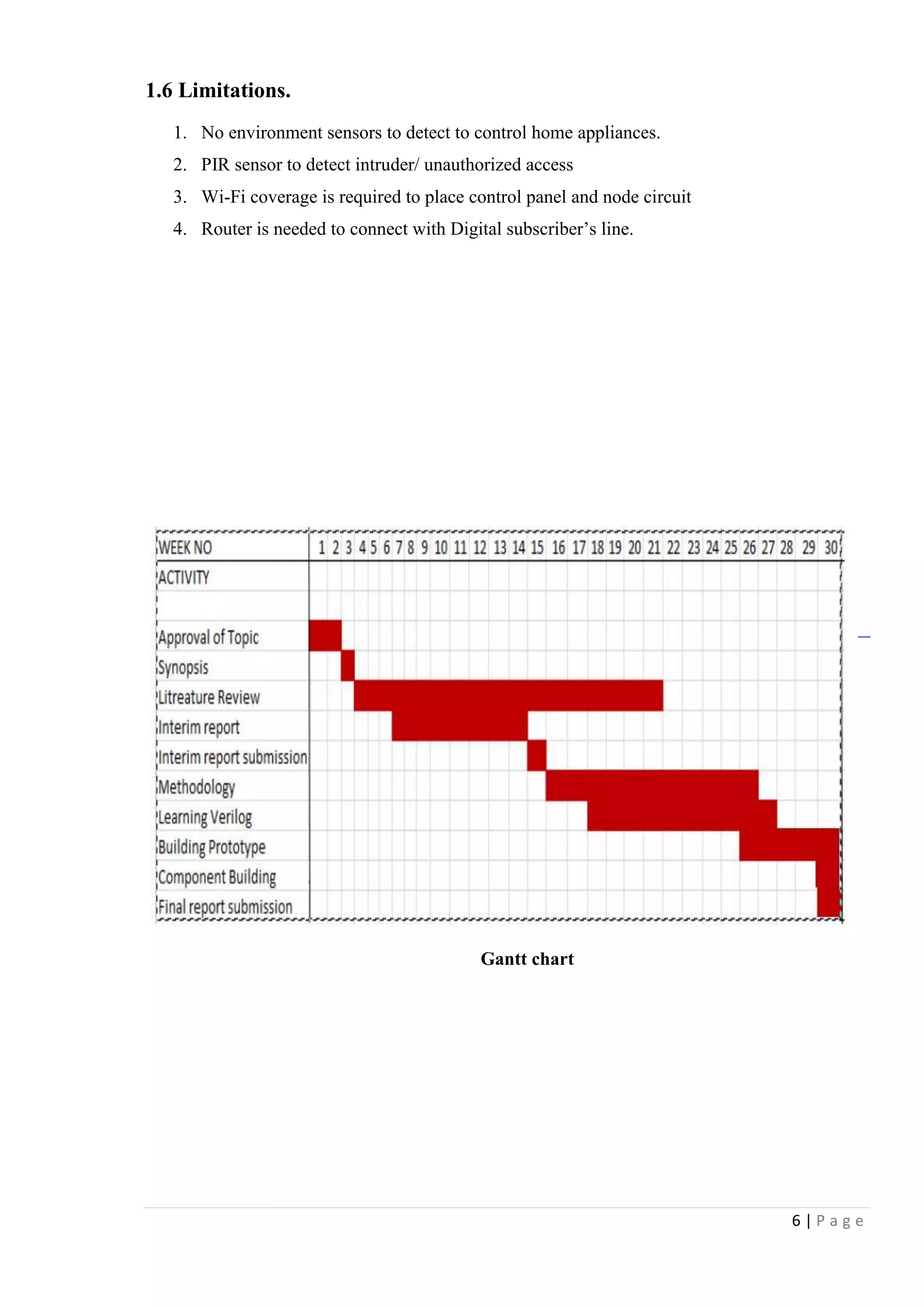
Need of home automation is needed to reduce human involvement in doing some activities and
it replaces considerable amount of human work force. Also it results in, saving the energy by
reducing cycle time, labor and material waste and to improve quality, accuracy and precision. It
supports people to do tasks that involve hard physical or tedious work, tasks done in dangerous
environments,
Nowadays automation does a huge role in increasing of productivity, quality and robustness in
human needs. This is why this project looks into construction and implementation of a system
involving hardware to control variety of electrical and electronics systems.](https://image.slidesharecdn.com/home-security-automation-160216085121/75/Home-security-automation-4-2048.jpg)
![12 | P a g e
Chapter 3 –Methodology
3.1 Design 1- Using X.10 Module and Web server
Design overview
Here the home automation system mainly functions using an X10 Wi-Fi module. The appliances
are linked via a micro sensor network and are linked to an ad hoc Wi-Fi data connection and
proposed to control by both user via Wi-Fi/internet and the programmable controller installed
inside the home. Here the main feature is such that the appliances and sensor network are linked
via faster and pretty stable Wi-Fi connection. But all systems are not perfect invincible and it is
a truth for this as well. The drawbacks of this model are that installation cost is still considered
very high and the need of internet to allow remote access. The cost of the hardware components
also remains at significantly high than some other technologies have limited their usability for
moderate houses. The figure 3.1A sketches out a mapping of devices and access in a X10 linked
home automation system.
Appliance- Device, which need to control
remotely.
Relay- Turn On/Off power supply by the
command
X.10 Module- Data converts in to voltage
signal
Main Control panel- Arduino Mega,
Control input/output signals as the program
written.
Web server- Store operation history, allow
user to access through remote device.
Sensor- detects unauthorized access and
gives signal to main control panel.
Actuator- external devices such as door
lock, Alarm sounders.
Remote device- Mobile phone/ Desktop
Figure 3.1A [Drawn by Microsoft word]](https://image.slidesharecdn.com/home-security-automation-160216085121/75/Home-security-automation-12-2048.jpg)
![13 | P a g e
Figure 3.1B shows the basic diagram for X.10 home automation systems
230V AC Power line
Relay module
PIR Sensor
Sounder Beacon
Web Server
Control PanelAppliance
Figure 3.1B [Drawn by Microsoft word]](https://image.slidesharecdn.com/home-security-automation-160216085121/75/Home-security-automation-13-2048.jpg)
![14 | P a g e
3.2 Design 2- Using Single Arduino Board
In this design the appliances connected to home automation system are controlled by the
Arduino Single Board computer. The Arduino provides more flexibility and agility to the
proposed system because it allows easy interfacing with most of the transducers used in today‟s
applications. As depicted in the Figure 3.2A the control signals received from Arduino supposed
to be authenticated and distributed via a network of relay devices and the advantages are easy
user interactions via keypads, remote access via Ethernet, gsm/gprs, Wi-Fi and many more. On
the other hand this may also leads to cutoff the budget since the Arduino systems are free and
open source platforms. The drawback and the difficulty faced by the user is the requirement of
the awareness of Arduino programming and interfacing with sensors and actuators and other
passive electronic devices such as Wi-Fi modules, GSM modules, Ethernet modules…etc. Main
disadvantage of the systems is, additional wires required from main panel to each appliance and
also inputs outputs are limited since single Arduino control panel.
Appliance- Device, which need to control
remotely.
Relay- Turn On/Off power supply by the
command
Switch- Manual operated switch to turn on/off
appliance, located at appliance
Feedback module- Gives a feedback signal to
main panel, when device appliance turned on
manually.
Control panel- Arduino Mega, Control
input/output signals as the program written.
Sensor- detects unauthorized access and gives
signal to main control panel.
Actuator- external devices such as door lock,
Alarm sounders.
GSM module: provides remote access over
GSM net work
Remote device- Mobile phone/ Desktop
Figure 3.2A [Drawn by Microsoft word]](https://image.slidesharecdn.com/home-security-automation-160216085121/75/Home-security-automation-14-2048.jpg)
![15 | P a g e
Figure 3.2B [Drawn by Microsoft word]](https://image.slidesharecdn.com/home-security-automation-160216085121/75/Home-security-automation-15-2048.jpg)
![16 | P a g e
3.3 Design 3- Using two Arduino Boards: Optimum Design
Node Circuit
Main Control panel circuit
Figure 3.3A [Drawn by Microsoft word]
Figure 3.3B [Drawn by Microsoft word]](https://image.slidesharecdn.com/home-security-automation-160216085121/75/Home-security-automation-16-2048.jpg)
![17 | P a g e
Appliance- Device, which is needs to control remotely.
Relay- Turn On/Off power supply to the appliance by the command
Switch- Manual operated switch to turn on/off appliance, located at appliance
Feedback module- Gives a feedback signal to main panel, when device appliance turned on
manually.
Node Panel- Arduino Mini, Control input/output signals as command by main panel.
Wi-Fi Module- use to communicate with router through main board
Sensor- detects unauthorized access and gives signal to main control panel.
Actuator- external devices such as door lock, Alarm sounders.
Router: Provide TCP/IP connectivity to access main panel over internet
Remote device- Mobile phone/ Desktop
The method proposed supposed to control and actuate via the node panels and each node
connected to central located main control panel. They are either parallel or serial connected to
the individual transducer (or sensor or actuator) and obtain the controls from Wi-Fi. Here the
main issue could be if one node is down to some reason the whole process of node part could go
blind since the dependency of each node is high. Main advantage of the panel is reducing of
wiring between appliances and control panel. Node panel can be located at any place within Wi-
Fi limit. Appliances can set more than one for each node.
Figure 3.3C [Drawn by Microsoft word]](https://image.slidesharecdn.com/home-security-automation-160216085121/75/Home-security-automation-17-2048.jpg)
![21 | P a g e
4.1.1 Arduino MEGA
The Arduino Mega is a microcontroller board based on the ATmega1280. It has 54 digital
input/output pins (of which 14 can be used as PWM outputs), 16 analog inputs, 4 UARTs
(hardware serial ports), a 16 MHz crystal oscillator, a USB connection, a power jack, an ICSP
header, and a reset button. It contains everything needed to support the microcontroller; simply
connect it to a computer with a USB cable or power it with a AC-to-DC adapter or battery to get
started. The Mega is compatible with most shields designed for the Arduino Duemilanove or
Diecimila. [ https://www.arduino.cc/en/Main/arduinoBoardMega]
Summary
Microcontroller ATmega1280
Operating Voltage 5V
Input Voltage (recommended) 7-12V
Input Voltage (limits) 6-20V
Digital I/O Pins 54 (of which 15 provide PWM output)
Analog Input Pins 16
DC Current per I/O Pin 40 mA
DC Current for 3.3V Pin 50 mA
Flash Memory 128 KB of which 4 KB used by boot loader
SRAM 8 KB
EEPROM 4 KB
Clock Speed 16 MHz
The Arduino Mega can be powered using the USB connection or with an external power supply.
Power source automatically selected by arduino board
External (non-USB) power can come either from an AC-to-DC SMPS adapter (wall-wart) or
battery. The board can operate on an external supply of 6 to 20 volts. Smoothness of the power
supply is must for proper working and also durability. To overcome malfunctioning and
overheating it is recommended to maintain supply voltage within 6V to 12V. The adapter can be
connected by plugging a 2.1mm center-positive plug into the board's power jack. Leads from a
battery can be inserted in the GND and Vin pin headers of the POWER connector.](https://image.slidesharecdn.com/home-security-automation-160216085121/75/Home-security-automation-21-2048.jpg)
![22 | P a g e
4.1.2 Arduino UNO
The Arduino UNO is a microcontroller board originally based on the ATmega328P.. It has 14
digital input/output pins (of which 6 can be used as PWM outputs), 6 analog inputs, a 16 MHz
quartz crystal, a USB connection, a power jack, an ICSP header and a reset button. It contains
everything needed to support the microcontroller; simply connect it to a computer with a USB
cable or power it with a AC-to-DC adapter or battery to get started.
[https://www.arduino.cc/en/Main/arduinoBoardUno]
Specifications
Microcontroller ATmega328P
Operating Voltage 5V
Input Voltage (recommended) 7-12V
Input Voltage (limit) 6-20V
Digital I/O Pins 14 (of which 6 provide PWM output)
PWM Digital I/O Pins 6
Analog Input Pins 6
DC Current per I/O Pin 20 mA
DC Current for 3.3V Pin 50 mA
Flash Memory 32 KB (ATmega328P) of which 0.5 KB used by
bootloader
SRAM 2 KB (ATmega328P)
EEPROM 1 KB (ATmega328P)
Clock Speed 16 MHz
Power supply for the arduino UNO is same as Arduino MEGA](https://image.slidesharecdn.com/home-security-automation-160216085121/75/Home-security-automation-22-2048.jpg)
![24 | P a g e
4.1.4 12V 5 pin Relay
A relay is a simple electromechanical switch made up of an electromagnet and a set of contacts.
In this project 12V 5 pin relay is used to control home appliance and actuator. It has 2 pin for
activate by 12V DC supply and other 3 Pin for Normally open and normally close contacts. NO,
NC pins can drive 230V AC up to 7A for appliance turns on and off.
Specification
Operating voltage: 12V DC
Numbers of pin 5 (2 for coil, other 3 pins for switching dry contacts)
Max Amps can drive by contacts 10A/24V DC, 7A/240V AC
Frequency 50/60Hz
4.1.5 240V AC Relay
To detect whether appliance is on or off, 230V AC driven relay is used. It activates by the
supply of home appliance when it switch on.
Specification
Operating voltage: 240V AC
Numbers of pin 8 (2 for coil, other 6 pins for switching dry contacts)
Max Amps can drive by contacts 5A/24V DC, 5A/240V AC
Frequency 50/60Hz
4.1.6 PIR Sensor
In here RK410PT PIR sensor used to detect human motion. This sensor has relay contact, which
will be triggered when some motion has detected by object exceeding 33KG [3]. It can be
directly connected with analog input terminal of the Adriano with 5V in other side](https://image.slidesharecdn.com/home-security-automation-160216085121/75/Home-security-automation-24-2048.jpg)
![25 | P a g e
4.1.7 D400 Transistor
D400 is a silicon made NPN transistor can be used as Low-Frequency Power Amp and also as a
electronic switch. It can drive up to 25V collector to base, Collector to emitter and also 5V
Emitter to base. Collector power dissipation 900mW [4]
[http://pdf.datasheetcatalog.com/datasheets2/45/455733_1.pdf]
4.1.8 10K Resistor
A resistor is an electrical component that limits or regulates the flow of electrical current in an
electronic circuit. Resistors can also be used to provide a specific voltage for an active device
such as a transistor. In here 10K resister is used to control and supply voltage to Transistor base
pin.
4.1.9 Two way switch
Two witch is coupled with 5 pin relay to operate as two way switching function for home
appliance. Using this switch user can turn on/ off appliance independency by remote operator.
4.1.10 Actuator
Actuator is a 12V electro magnetically operated door lock, which can be connected via relay
circuit. This is useful to control access of home main door garage doors and any doors as
requirement. Door lock can handle up to 200KG weight as manufacture‟s specification.
D400 Transistor 10K Resistor Two way switch](https://image.slidesharecdn.com/home-security-automation-160216085121/75/Home-security-automation-25-2048.jpg)
![26 | P a g e
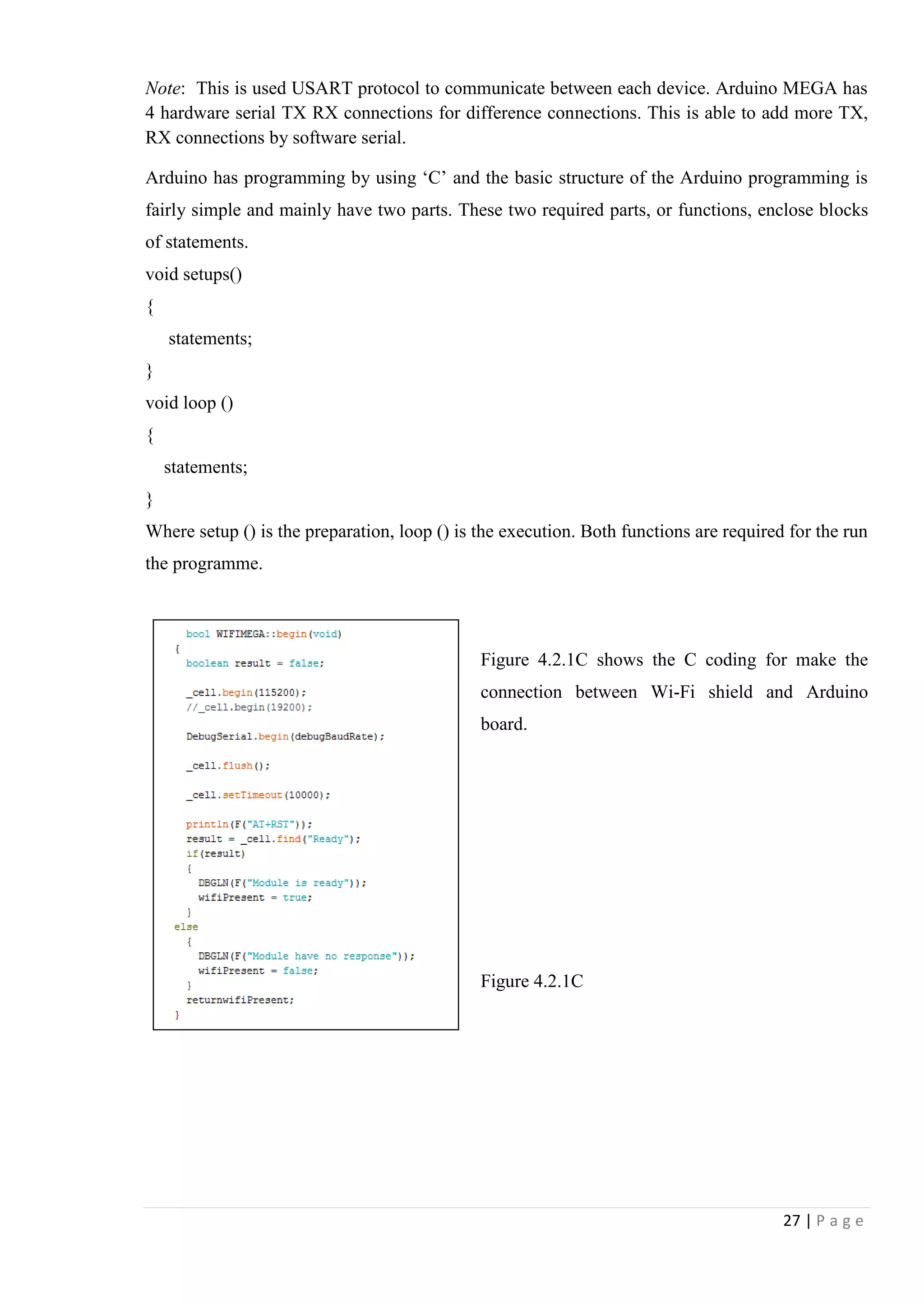
4.2 Hardware and Software Configuration
4.2.1 Connection between Arduino MEGA and Wi-Fi Shield.
Wi-Fi Shield Arduino MEGA Power by USB
Wi-Fi shield pin-out details
1. TX- with Arduino RX
2. V+ - 3.3V supplied from Arduino
3. Not in use
4. Not in use
5. Not in use
6. Not in use
7. Ground connected
8. RX- setup to TX in Arduino
Description
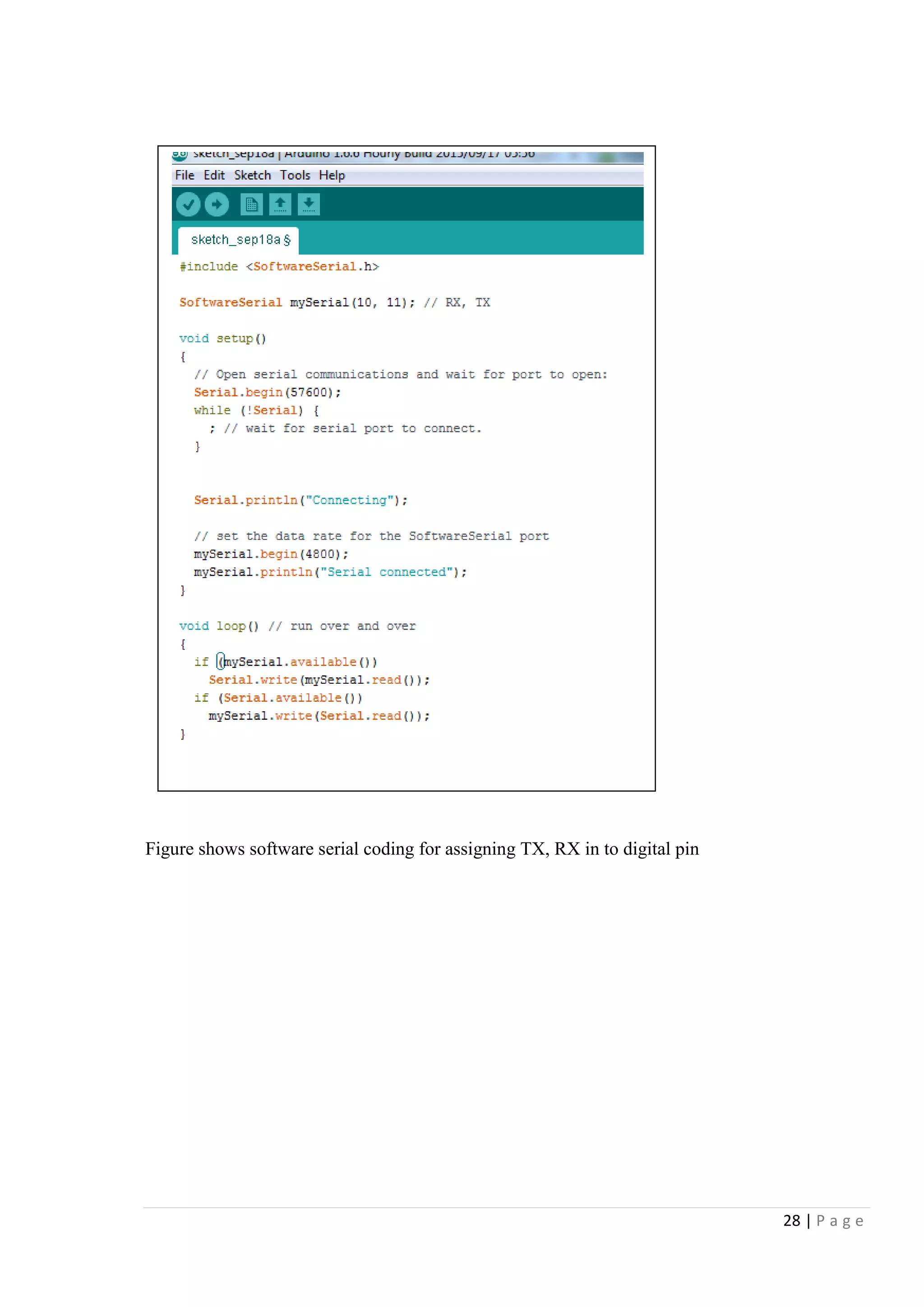
The Wi-Fi module communicates with the host Arduino mega using the serial communication at
19200 bauds per second. The Arduino mega is the master device hence responsible for
collecting and processing the data from the transducers attached
Figure 4.2.1A [Drawn by MS paint]
Figure 4.2.1B [From prototype]](https://image.slidesharecdn.com/home-security-automation-160216085121/75/Home-security-automation-26-2048.jpg)
![29 | P a g e
4.2.2 Connection between Arduino UNO and Wi-Fi Shield
Arduino UNO Wi-Fi Shield USB Power
Wi-Fi shield pin
1. TX- with RX in Arduino
2. V+ - 3.3V supplied from Arduino
3. Not in use
4. Not in use
5. Not in use
6. Not in use
7. Ground connected
8. RX- with TX in Arduino
Description:
The Wi-Fi module communicates with the host Arduino Uno using the serial communication at
19200 bauds per second. The Arduino Uno is the slave device hence responsible for transferring
the requested data to the Arduino mega master device.
Figure 4.2.2A [Drawn by MS paint]
Figure 4.2.1B [From prototype]](https://image.slidesharecdn.com/home-security-automation-160216085121/75/Home-security-automation-29-2048.jpg)
![30 | P a g e
4.2.3 Connection between Appliance and Arduino UNO
10 K Resistors
Transistor
IN 4001Diode
Relay
1. Digital pin 5 for relay driven circuit
2. Common is connected together
3. 12V relay work as switch
4. Transistor drives 12V relay
5. 10K resistor to reduce voltage to transistor base
6. Diode to transistor protection
7. NO, C, NC can be used as requirement
Figure 4.2.3A [Drawn by MS paint]
Figure 4.2.3BB [From prototype]](https://image.slidesharecdn.com/home-security-automation-160216085121/75/Home-security-automation-30-2048.jpg)
![31 | P a g e
Description:
The actuation of components is accommodated by the relay device. The relay is an electrically
magnetized coil and with and without signal it acts as an open or close switch. The relays are
capable of operating under rough conditions is a key in this work.
Interfacing Output relay for Appliance
Figure 4.2.3C shows that the programming code for activate the relay output pin in Arduino
UNO board as in shown when the serial read as A, it gives a command to make the value high in
associated pin.
Figure 4.2.3C [From Arduino Software]](https://image.slidesharecdn.com/home-security-automation-160216085121/75/Home-security-automation-31-2048.jpg)
![32 | P a g e
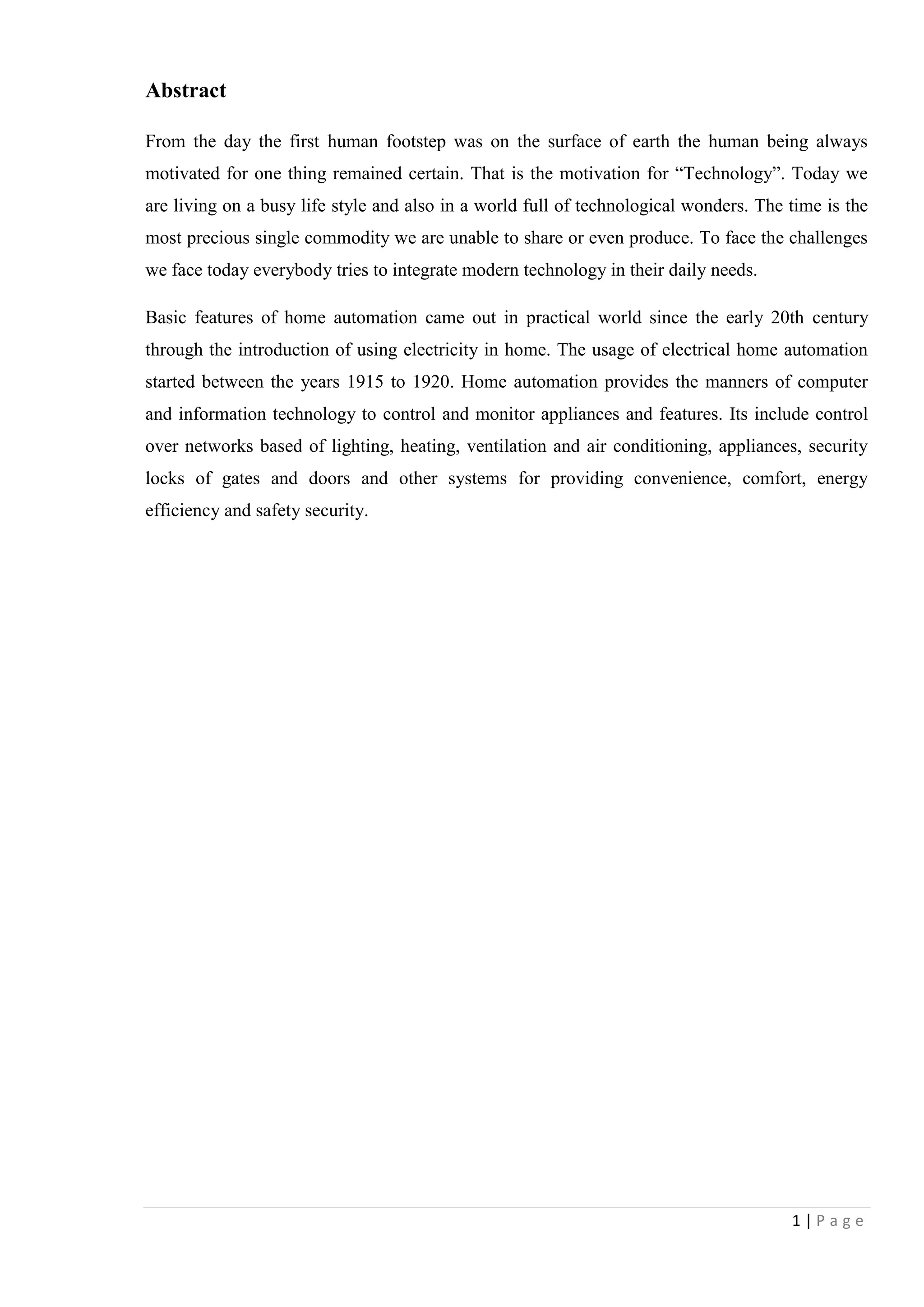
4.2.4 Feedback connectivity
1. 230 AC relay will activate if somebody turns on the appliance manually
2. NO dry contact gets 5V from Arduino
3. 5V received by analog in A0. It will work as feedback
Description:
When the relay gets a on signal it is directed back to Arduino Uno with a OR logic circuit
created. This is active for both manual and remote operation.
Figure 4.2.4A [drawn by MS paint]
Figure 4.2.4B [From prototype]](https://image.slidesharecdn.com/home-security-automation-160216085121/75/Home-security-automation-32-2048.jpg)
![33 | P a g e
Interfacing Feedback Relay
Figure 4.2.4C elaborated how to be programmed Arduino software coding to read current status
of the appliance by getting value to analog pin A0.
Figure 4.2.4C [From Arduino Software]](https://image.slidesharecdn.com/home-security-automation-160216085121/75/Home-security-automation-33-2048.jpg)
![34 | P a g e
4.2.5 PIR Sensor Connectivity
PIR Sensor
External 12V DC power source is
required
R Relay dry contact
PIR sensor connects with PWM pin 6 and 7
Description:
PIR gives a signal when it detects motion and Arduino notices the change and does the
necessary process activations.
Figure 4.2.5B [From prototype]
Figure 4.2.4A [Drawn by MS Paint]](https://image.slidesharecdn.com/home-security-automation-160216085121/75/Home-security-automation-34-2048.jpg)
![35 | P a g e
Here used PIR sensor and feedback relay as inputs. They all output analog DC voltages to
processor. Then inbuilt registers of processor (Arduino) convert that analog input to digital.
These digital 10 bit outputs have 1024 quantization level and therefore can have sensitive output
to processor. Therefore when sensor produces output, it can be monitored as digital valve.
0V 0000000000 = 010
5V 1111111111 = 102310
Interfacing PIR Sensor –Important Section of programming
Figure 4.2.4C has shown coding it had used to detect the PIR relay signal and assign in to
integer pir. Motion is detect by Arduino MEGA.
Figure 4.2.4C [From Arduino Software]](https://image.slidesharecdn.com/home-security-automation-160216085121/75/Home-security-automation-35-2048.jpg)
![36 | P a g e
4.3 Randomly turns on and off lights for security purposes
Random operation of lights is designed to add additional feature to security system. This will
help to mislead intruder trying to entering premises. Random operation of lights convinces that
residents are at home.
Figure 4.3 [from arduino software]
Figure 4.3 elaborate Arduino coding set a timer to output pin. Lights can be set to turn on/off
within specific time period.](https://image.slidesharecdn.com/home-security-automation-160216085121/75/Home-security-automation-36-2048.jpg)
![37 | P a g e
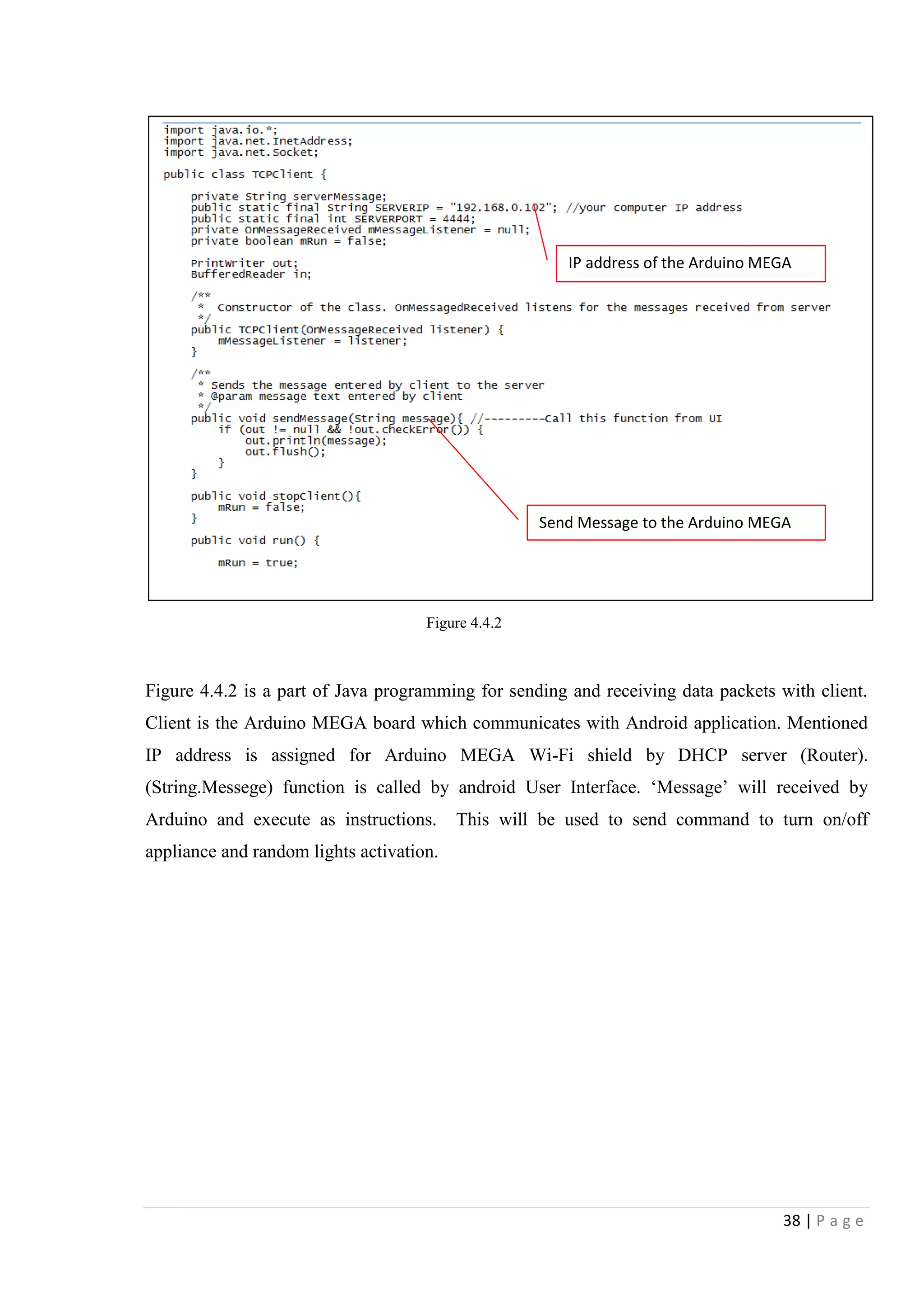
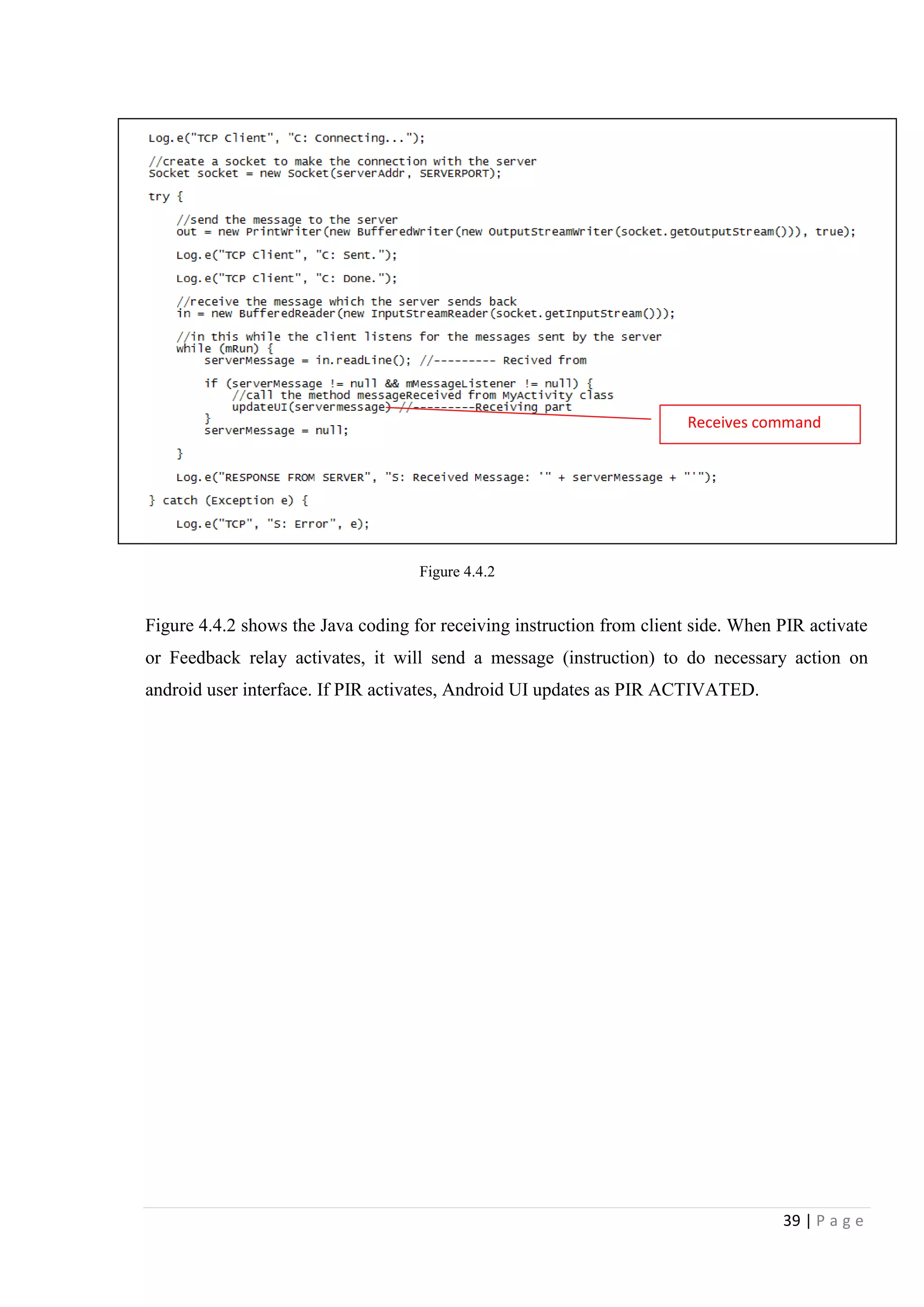
4.4 Remote Access
4.4.1 Android Application GUI
Android
Android is a mobile operating system (OS) based on the Linux kernel. With a user
interface based on direct manipulation, Android is designed primarily for touch screen mobile
devices such as smart phones and tablet computers. There are millions of android applications
are available to free download on Google‟s play store and many other third party sources. Some
developers choose to make their apps available to download from their own sites or alternative
app stores Main advantage of this OS is open source capability.
Current status of the device is off
Current status of the device is ON
Turns ON/OFF random light mode when leaving home
Notify when the PIR activates
Figure 4.4.1 shows the android application Graphical user interface which is used to control
home appliances and it allow user to see current status of home appliances. It will notify that
when some motion detected by PIR sensor.
Figure 4.4.1 [By MS word]](https://image.slidesharecdn.com/home-security-automation-160216085121/75/Home-security-automation-37-2048.jpg)
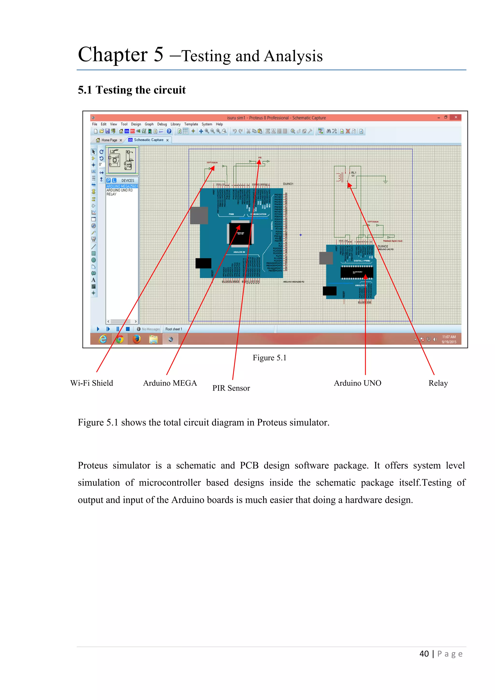
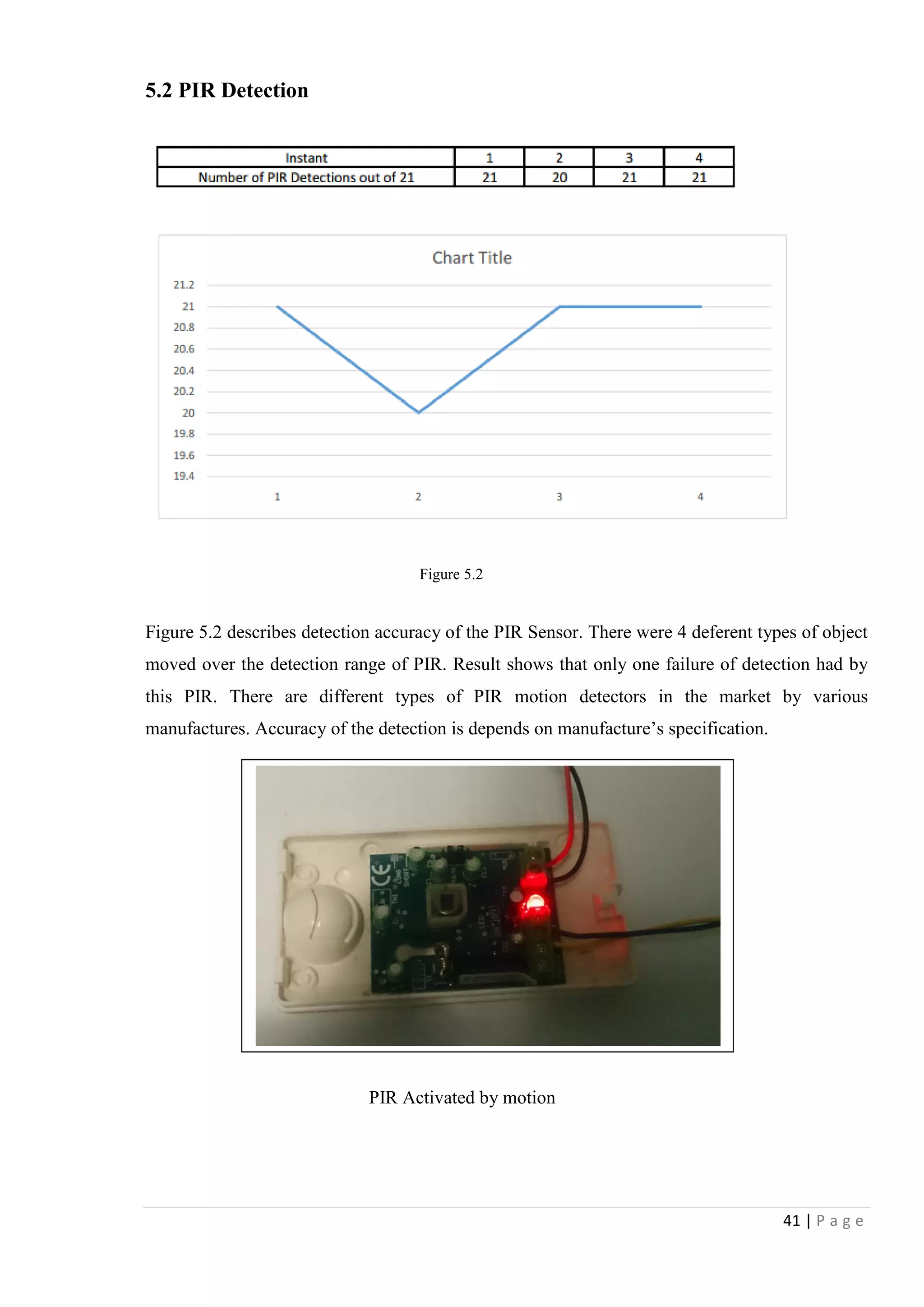
![42 | P a g e
5.3 Testing of two way Switch and feedback Relay
Figure 5.3 shows the circuit connectivity of appliance wall outlet, manual control switch, remote
control Relay circuit and feedback relay to inform that whether appliance is on or off. When
wall outlet powered, feedback relay will trigger. Use of the AC power detection circuit is better
than using of AC relay because of the characteristic of AC Relay. Relay has limited switching
time and get heated when long time working. Therefore as further development, power detection
circuit will be added.
Figure5.3 [from prototype]
Relay control
by Arduino
Feedback relay
Wall outlet
Manual
switch](https://image.slidesharecdn.com/home-security-automation-160216085121/75/Home-security-automation-42-2048.jpg)
![43 | P a g e
Figure 5.4 elaborate the connection between feedback relay and Arduino UNO board
Figure5.4 [from Proteus Simulator]](https://image.slidesharecdn.com/home-security-automation-160216085121/75/Home-security-automation-43-2048.jpg)
![44 | P a g e
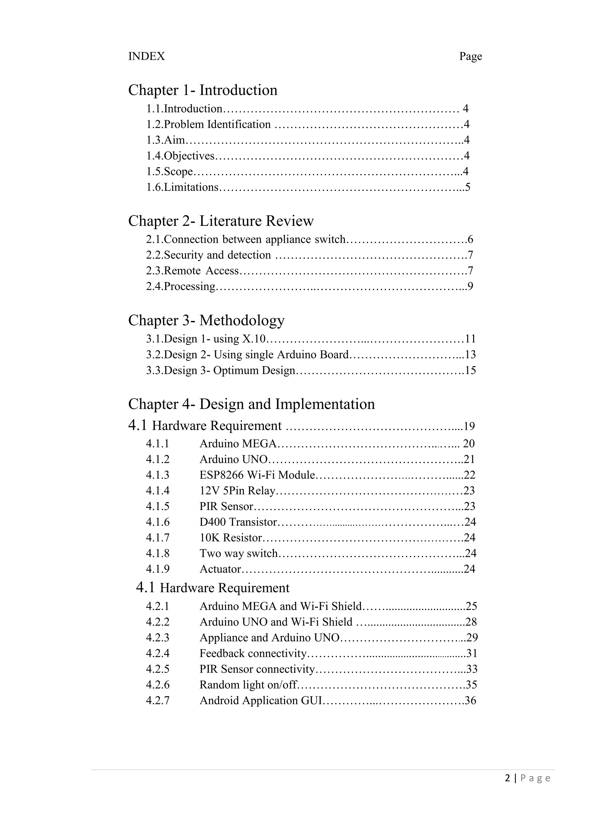
5.4 Control appliances over android application
Figure 5.5 [captured from prototype 2]
Figure 5.5 shows operation of Arduino home automation system using android application
which is available to download from Google‟s play store. We can set input and output as our
requirement
Wi-Fi Module
ATmega328P
Android App
Light 1 ON
Light 1 OFF
Light 1 turned off from App](https://image.slidesharecdn.com/home-security-automation-160216085121/75/Home-security-automation-44-2048.jpg)

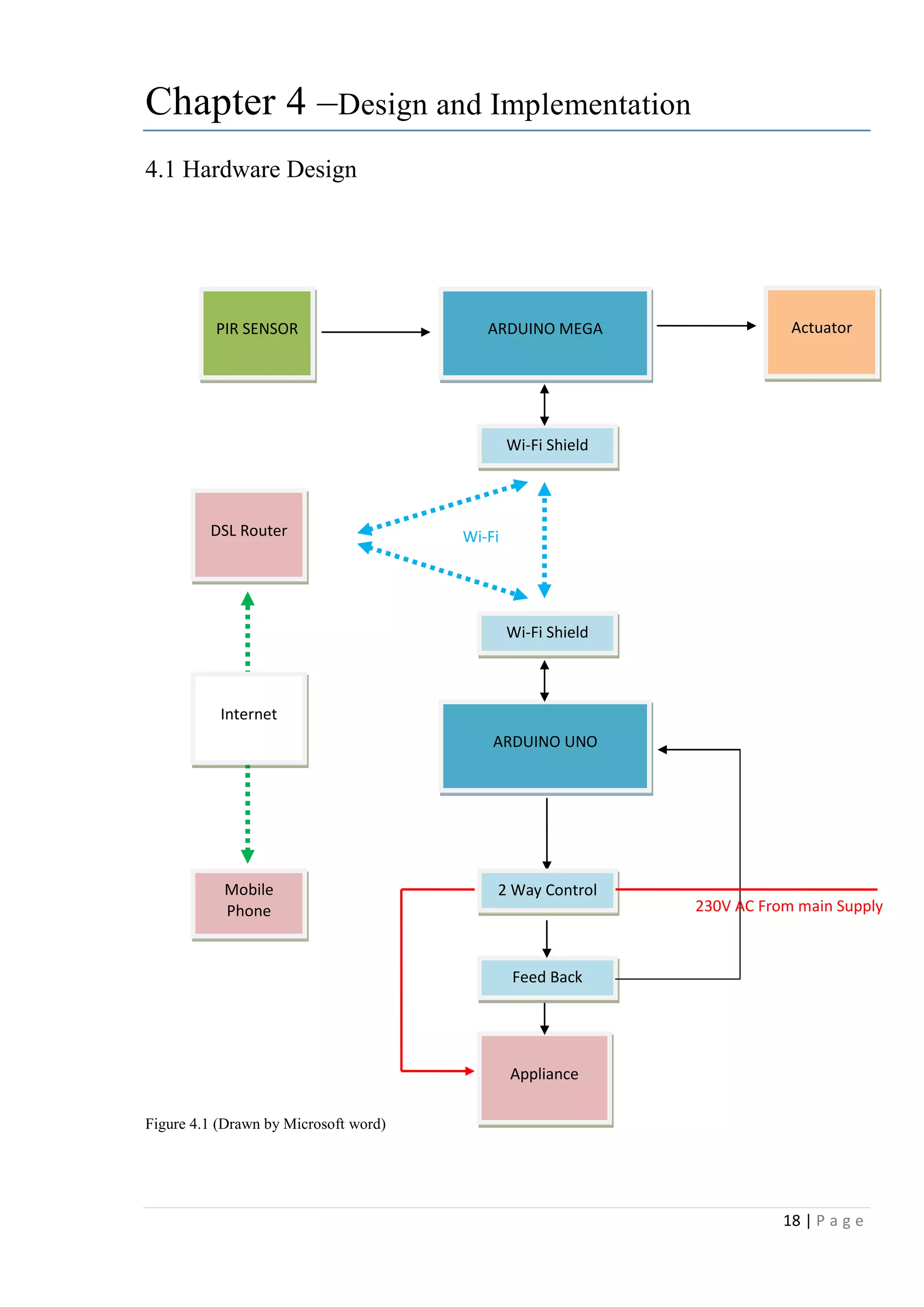
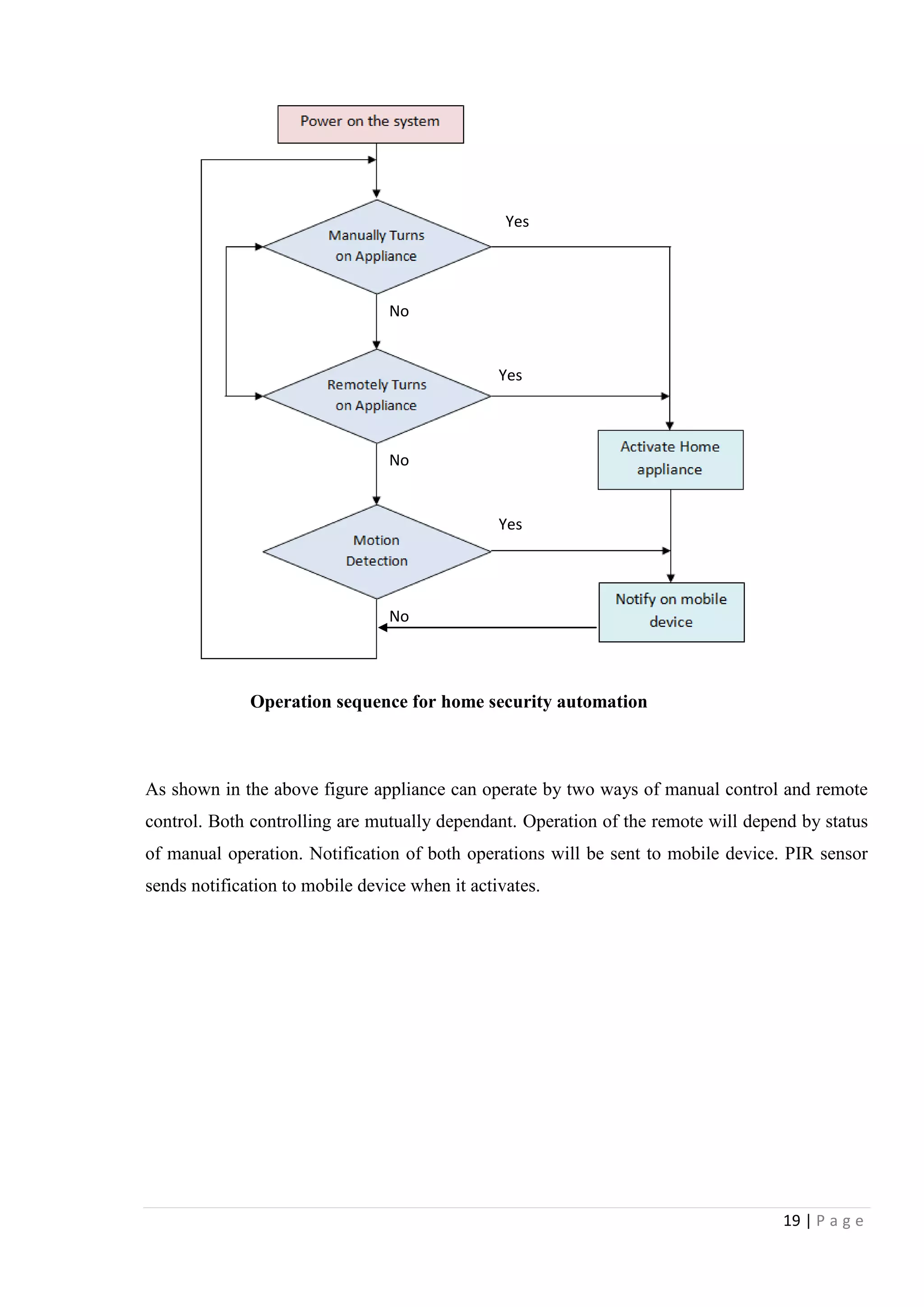
This document discusses home security automation and its objectives. It aims to design and implement a home security automation system to control basic appliances while providing security features like motion detection. The system will identify the current status of appliances, detect human motion, read input signals from the control panel, and allow remote users to turn appliances on/off over the internet. It will also randomly turn lights on/off for security and connect appliances to output relays for remote control. Literature on connecting appliances to switches and control panels, security and motion detection, and remote access is reviewed. The hardware and software design, implementation, testing, and analysis of the system are outlined.