This document discusses the numerical control programming of a shield part using MasterCAM software. It describes the tool paths and operations used to machine the shield from an aluminum blank, including facing, contouring, pocketing, engraving, and scalloping. The finished machined shield meets the specifications of being 110mm x 86mm in size and 19mm thick. While the project was generally successful, it is recommended to improve the tool path for pocketing operation and potentially add post-processing steps to improve surface finish.

![II
List of Figures
Figure 1 Work piece to be CNC machined (Project #1 NC Programming of Machine Tools, 2014) .............2
Figure 2 Facing Operation ...................................................................................................................3
Figure 3 Climb vs. Conventional Cutting[ (Cutting Tool Fundamentals - Rotation Direction, 2012)]..........4
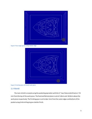
Figure 4 Two rough passes along shorteredge .....................................................................................5
Figure 5 Finishing pass all around work piece .......................................................................................5
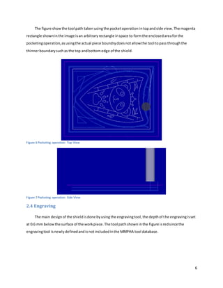
Figure 6 Pocketing operation: Top View...............................................................................................6
Figure 7 Pocketing operation: Side View ..............................................................................................6
Figure 8 Engraving Operation..............................................................................................................7
Figure 9 Scalloping of the shield ..........................................................................................................7
Figure 10 Scalloping of the Base ..........................................................................................................7
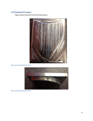
Figure 11 Finished Shield TopView......................................................................................................8
Figure 12 Finished Shield Side View .....................................................................................................8](https://image.slidesharecdn.com/704d6f28-6f7c-4ca9-889e-7d9a134ca523-160404160624/85/Project-report-1-3-320.jpg)
![III
List of Tables
Table 1 Feed rates for Foam and Aluminum [ (Project #1 NC Programming of Machine Tools, 2014)] ......2](https://image.slidesharecdn.com/704d6f28-6f7c-4ca9-889e-7d9a134ca523-160404160624/85/Project-report-1-4-320.jpg)
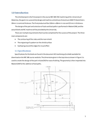
![2
Figure 1 Work piece to be CNC machined (Project #1 NC Programming of Machine Tools, 2014)
In orderto achieve these featuresabove andasmentionedinthe Introduction,threetoolsare
allowedtobe usedincombination:
½” (12.7 [mm]) 2-flutedEndmill
¼” (6.35 [mm]) ball nose Endmill
EngravingTool,<1 [mm] diameter
The spindle speed,plungerate andx,y axisfeedforeachof the toolsare specifiedinTable 1below
for aluminum. The plungerate ischangedto500mm/min inthe actual machinine processtospeedup
the completionof the shield.
Table 1 Feed rates for Foam and Aluminum [ (Project #1 NC Programming of Machine Tools, 2014)]](https://image.slidesharecdn.com/704d6f28-6f7c-4ca9-889e-7d9a134ca523-160404160624/85/Project-report-1-6-320.jpg)

![4
o Depthcut at maximum 10 mmeach
o 0.65 mm stock to leave onwalls
Finishing
o One pass to take off the 0.65 stock usingclimb milling
The rough passesuse conventionalcutting,since the tool isunderlessstresswhencominginto
contact withthe material at the thinneredge,and istherefore abletocutthickeramountof materials
quickly.
Whenfinishingthe edges,climbmillingisusedinordertogive abettersurface finish;the smaller
amountof materialsremovedmitigatesthe initial jumpinstresswhenthe tool firstcomesintocontact
withthe workpiece.
The figuresbelowshowthe difference betweenclimbandconventional milling,andthe generated
tool path forthisoperationinMasterCAM.
Figure 3 Climb vs.Conventional Cutting [ (Cutting Tool Fundamentals - Rotation Direction, 2012)]](https://image.slidesharecdn.com/704d6f28-6f7c-4ca9-889e-7d9a134ca523-160404160624/85/Project-report-1-8-320.jpg)
![7
Figure 8 Engraving Operation
2.5 Scallops
The scallopsare addedto the shieldforvisual appearancesonly.The tool usedisthe ¼”(6.35
[mm]) ball nose endmill,andthe cuttingdepthis -0.9 mm and-8.3 mm showninFigure 9 forthe shield
and base edges.The depthisarbitrarilydefined asthe operationisforvisual purposesonly.
Figure 9 Scalloping of the shield
Figure 10 Scalloping of the Base](https://image.slidesharecdn.com/704d6f28-6f7c-4ca9-889e-7d9a134ca523-160404160624/85/Project-report-1-11-320.jpg)