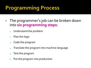
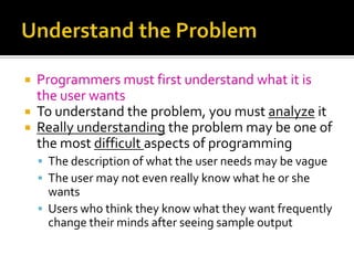
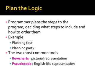
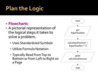
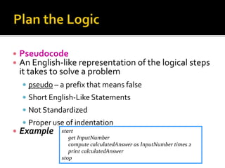
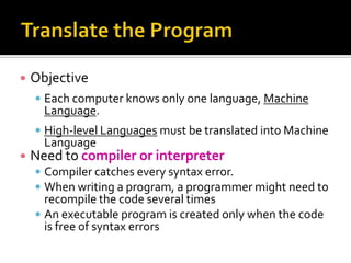
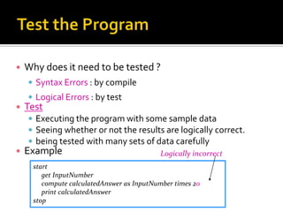
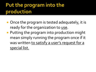
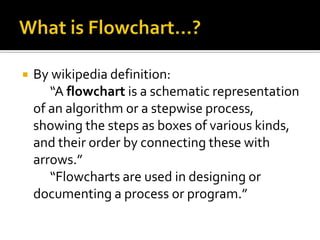
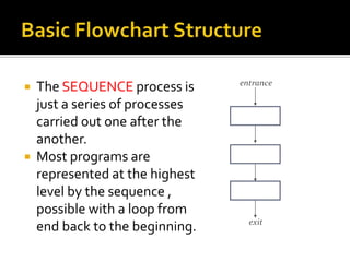
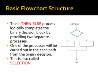
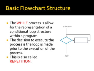
Prepared by:
Mr. Richard R. Basilio
BSECE –T Dip IC
   The programmer’s job can be broken down
    into six programming steps:
    1. Understand the problem

    2. Plan the logic

    3. Code the program

    4. Translate the program into machine language

    5. Test the program

    6. Put the program into production
 Programmers must first understand what it is
  the user wants
 To understand the problem, you must analyze it
 Really understanding the problem may be one of
  the most difficult aspects of programming
     The description of what the user needs may be vague
     The user may not even really know what he or she
      wants
     Users who think they know what they want frequently
      change their minds after seeing sample output
 Programmer plans the steps to the
  program, deciding what steps to include and
  how to order them
 Example
   Planning tour
   Planning party
 The two most common tools
   flowcharts : pictorial representation
   Pseudocode : English-like representation
start
   Flowcharts
   A pictorial representation of              get
    the logical steps it takes to         InputNumber
    solve a problem.
     Uses Standardized Symbols         calculatedAnswer =
                                         InputNumber * 2
     Utilize Formula Notation
     Typically Read from Top to               print
      Bottom or from Left to Right on   calculatedAnswer
      a Page
                                               stop
   Pseudocode
   An English-like representation of the logical steps
    it takes to solve a problem
     pseudo – a prefix that means false
     Short English-Like Statements
     Not Standardized
     Proper use of indentation
   Example    start
                  get InputNumber
                  compute calculatedAnswer as InputNumber times 2
                  print calculatedAnswer
               stop
   Writing the program in one of more than 400
    programming languages
     Pascal, Assembly Language, C, C++, Java…..
   Concentrate on the syntax of the language
     Exact instruction, symbol, …. ?
   Some very experienced programmers
     successfully combining the logic planning and the
      actual instruction writing, or coding of the program, in
      one step
     Writing a cinema scenario
   Objective
     Each computer knows only one language, Machine
      Language.
     High-level Languages must be translated into Machine
      Language
   Need to compiler or interpreter
     Compiler catches every syntax error.
     When writing a program, a programmer might need to
      recompile the code several times
     An executable program is created only when the code
      is free of syntax errors
   Why does it need to be tested ?
     Syntax Errors : by compile
     Logical Errors : by test
   Test
     Executing the program with some sample data
     Seeing whether or not the results are logically correct.
     being tested with many sets of data carefully
   Example                                 Logically incorrect
      start
         get InputNumber
         compute calculatedAnswer as InputNumber times 20
         print calculatedAnswer
      stop
   Once the program is tested adequately, it is
    ready for the organization to use.
   Putting the program into production might
    mean simply running the program once if it
    was written to satisfy a user’s request for a
    special list.
   By wikipedia definition:
       “A flowchart is a schematic representation
    of an algorithm or a stepwise process,
    showing the steps as boxes of various kinds,
    and their order by connecting these with
    arrows.”
       “Flowcharts are used in designing or
    documenting a process or program.”
Start/Stop      Process     Input/Output
(Terminator)   (Rectangle)   (Parallelogram)


 Decision      Connector       Flowlines       Predefined Process
(Diamond)       (Circle)        (Arrows)           (Rectangle)
   Input/Output
       Generalised Input/Output
    Block; reading data from an
    input medium or writing data to
    an output medium. This block       Input/Output
                                       (Parallelogram)
    should be used in situation were
    data is being sent in and out of
    the processor via some sort of
    I/O peripheral.
   Process
        Any process step; an
    operation or group of
    operations that cause a
    change in value, form or       Process
    location of the data. This   (Rectangle)

    can consist of arithmetic
    or logical operators or
    even move commands.
   Flow line
        Sequence of operations
    and direction of data flow;
    arrowheads are required if
    linkage is not left-to-right   Flowlines
    or top-to-bottom.               (Arrows)

    Generally arrowheads are
    included to avoid
    confusion.
   Annotation
       Additional explanation or
    comments. This block is
    used for providing
    additional information to
    any other block in the
    flowchart.
   Decision
        Decision-making or
    switching type of
    operation, usually based on
    a comparison, that
                                   Decision
    determines which of a         (Diamond)

    number of paths should be
    followed.
   Predefined Process
       One or more operation
    defined in more detail
    elsewhere, such as in a
    booklet or on a different
    flowchart, but not on       Predefined Process
                                    (Rectangle)
    another part of the
    flowchart in which this
    symbol appears.
   Terminal
       Terminal point in a
    flowchart – stop, start or
    break in the line of flow.


                        Start/Stop
                       (Terminator)
   Connectors
        Entry to or exit from
    another part of the
    flowchart; if to or from step
    is on another page then the
    page reference should also
    be stated.                      Connector
                                     (Circle)
   Use a standardized flowcharting template,
    with clearly recognizable symbols. Follow ANSI
    recommendations for symbol use.
   Do not crowd or clutter the flowchart, ensure
    proper spacing between symbols.
   Number the pages of your flowchart
    sequentially. Specifically the title of program,
    the date and the author on each separate
    page.
   Chart the main line of data flow in the system
    or program first, then incorporate detail in later
    flowchart.
   Write within symbols avoid using too many
    words. If necessary use the annotation symbol.
   Choose wording to suit the anticipated readers
    of the flowchart.
   Be legible, neatness counts.
   If flowchart becomes complex use connector
    symbols to reduce the number of flow lines.
   Collect incoming and outgoing flow lines so
    that the number of lines entering or leaving a
    symbol are minimized.
 Use the flowchart as a guide when coding;
  change it when necessary to ensure the
  flowchart reflects the steps implemented in the
  code.
 Cross-reference portion of the flowchart to the
  source language code.
 Be consistent with the level of detail shown in
  the flowchart. Do not chart every detail, but do
  not leave out important details.
   Put yourself in the position of the reader; try to
    anticipate the reader’s problems in
    understanding the flowchart.
 Sequence
 If-then-else (Selection)
 While (Repetition)
entrance
 The SEQUENCE process is
  just a series of processes
  carried out one after the
  another.
 Most programs are
  represented at the highest
  level by the sequence ,
  possible with a loop from
                                 exit
  end back to the beginning.
 The If-THEN-ELSE process       entrance
  logically completes the
  binary decision block by
  providing two separate
  processes.
 One of the processes will be
  carried out in the each path
  from the binary decision.
 This is also called
                                    exit
  SELECTION.
 The WHILE process is allow
                                  entrance
  for the representation of a
  conditional loop structure
  within a program.
 The decision to execute the
  process is the loop is made
  prior to the execution of the
  process.
                                   exit
 This is also called
  REPETITION.
Programming process and flowchart

Programming process and flowchart

  • 1.
    Prepared by: Mr. RichardR. Basilio BSECE –T Dip IC
  • 3.
    The programmer’s job can be broken down into six programming steps: 1. Understand the problem 2. Plan the logic 3. Code the program 4. Translate the program into machine language 5. Test the program 6. Put the program into production
  • 4.
     Programmers mustfirst understand what it is the user wants  To understand the problem, you must analyze it  Really understanding the problem may be one of the most difficult aspects of programming  The description of what the user needs may be vague  The user may not even really know what he or she wants  Users who think they know what they want frequently change their minds after seeing sample output
  • 5.
     Programmer plansthe steps to the program, deciding what steps to include and how to order them  Example  Planning tour  Planning party  The two most common tools  flowcharts : pictorial representation  Pseudocode : English-like representation
  • 6.
    start  Flowcharts  A pictorial representation of get the logical steps it takes to InputNumber solve a problem.  Uses Standardized Symbols calculatedAnswer = InputNumber * 2  Utilize Formula Notation  Typically Read from Top to print Bottom or from Left to Right on calculatedAnswer a Page stop
  • 7.
    Pseudocode  An English-like representation of the logical steps it takes to solve a problem  pseudo – a prefix that means false  Short English-Like Statements  Not Standardized  Proper use of indentation  Example start get InputNumber compute calculatedAnswer as InputNumber times 2 print calculatedAnswer stop
  • 8.
    Writing the program in one of more than 400 programming languages  Pascal, Assembly Language, C, C++, Java…..  Concentrate on the syntax of the language  Exact instruction, symbol, …. ?  Some very experienced programmers  successfully combining the logic planning and the actual instruction writing, or coding of the program, in one step  Writing a cinema scenario
  • 9.
    Objective  Each computer knows only one language, Machine Language.  High-level Languages must be translated into Machine Language  Need to compiler or interpreter  Compiler catches every syntax error.  When writing a program, a programmer might need to recompile the code several times  An executable program is created only when the code is free of syntax errors
  • 10.
    Why does it need to be tested ?  Syntax Errors : by compile  Logical Errors : by test  Test  Executing the program with some sample data  Seeing whether or not the results are logically correct.  being tested with many sets of data carefully  Example Logically incorrect start get InputNumber compute calculatedAnswer as InputNumber times 20 print calculatedAnswer stop
  • 11.
    Once the program is tested adequately, it is ready for the organization to use.  Putting the program into production might mean simply running the program once if it was written to satisfy a user’s request for a special list.
  • 13.
    By wikipedia definition: “A flowchart is a schematic representation of an algorithm or a stepwise process, showing the steps as boxes of various kinds, and their order by connecting these with arrows.” “Flowcharts are used in designing or documenting a process or program.”
  • 14.
    Start/Stop Process Input/Output (Terminator) (Rectangle) (Parallelogram) Decision Connector Flowlines Predefined Process (Diamond) (Circle) (Arrows) (Rectangle)
  • 15.
    Input/Output Generalised Input/Output Block; reading data from an input medium or writing data to an output medium. This block Input/Output (Parallelogram) should be used in situation were data is being sent in and out of the processor via some sort of I/O peripheral.
  • 16.
    Process Any process step; an operation or group of operations that cause a change in value, form or Process location of the data. This (Rectangle) can consist of arithmetic or logical operators or even move commands.
  • 17.
    Flow line Sequence of operations and direction of data flow; arrowheads are required if linkage is not left-to-right Flowlines or top-to-bottom. (Arrows) Generally arrowheads are included to avoid confusion.
  • 18.
    Annotation Additional explanation or comments. This block is used for providing additional information to any other block in the flowchart.
  • 19.
    Decision Decision-making or switching type of operation, usually based on a comparison, that Decision determines which of a (Diamond) number of paths should be followed.
  • 20.
    Predefined Process One or more operation defined in more detail elsewhere, such as in a booklet or on a different flowchart, but not on Predefined Process (Rectangle) another part of the flowchart in which this symbol appears.
  • 21.
    Terminal Terminal point in a flowchart – stop, start or break in the line of flow. Start/Stop (Terminator)
  • 22.
    Connectors Entry to or exit from another part of the flowchart; if to or from step is on another page then the page reference should also be stated. Connector (Circle)
  • 25.
    Use a standardized flowcharting template, with clearly recognizable symbols. Follow ANSI recommendations for symbol use.  Do not crowd or clutter the flowchart, ensure proper spacing between symbols.  Number the pages of your flowchart sequentially. Specifically the title of program, the date and the author on each separate page.
  • 26.
    Chart the main line of data flow in the system or program first, then incorporate detail in later flowchart.  Write within symbols avoid using too many words. If necessary use the annotation symbol.  Choose wording to suit the anticipated readers of the flowchart.
  • 27.
    Be legible, neatness counts.  If flowchart becomes complex use connector symbols to reduce the number of flow lines.  Collect incoming and outgoing flow lines so that the number of lines entering or leaving a symbol are minimized.
  • 28.
     Use theflowchart as a guide when coding; change it when necessary to ensure the flowchart reflects the steps implemented in the code.  Cross-reference portion of the flowchart to the source language code.  Be consistent with the level of detail shown in the flowchart. Do not chart every detail, but do not leave out important details.
  • 29.
    Put yourself in the position of the reader; try to anticipate the reader’s problems in understanding the flowchart.
  • 30.
     Sequence  If-then-else(Selection)  While (Repetition)
  • 31.
    entrance  The SEQUENCEprocess is just a series of processes carried out one after the another.  Most programs are represented at the highest level by the sequence , possible with a loop from exit end back to the beginning.
  • 32.
     The If-THEN-ELSEprocess entrance logically completes the binary decision block by providing two separate processes.  One of the processes will be carried out in the each path from the binary decision.  This is also called exit SELECTION.
  • 33.
     The WHILEprocess is allow entrance for the representation of a conditional loop structure within a program.  The decision to execute the process is the loop is made prior to the execution of the process. exit  This is also called REPETITION.