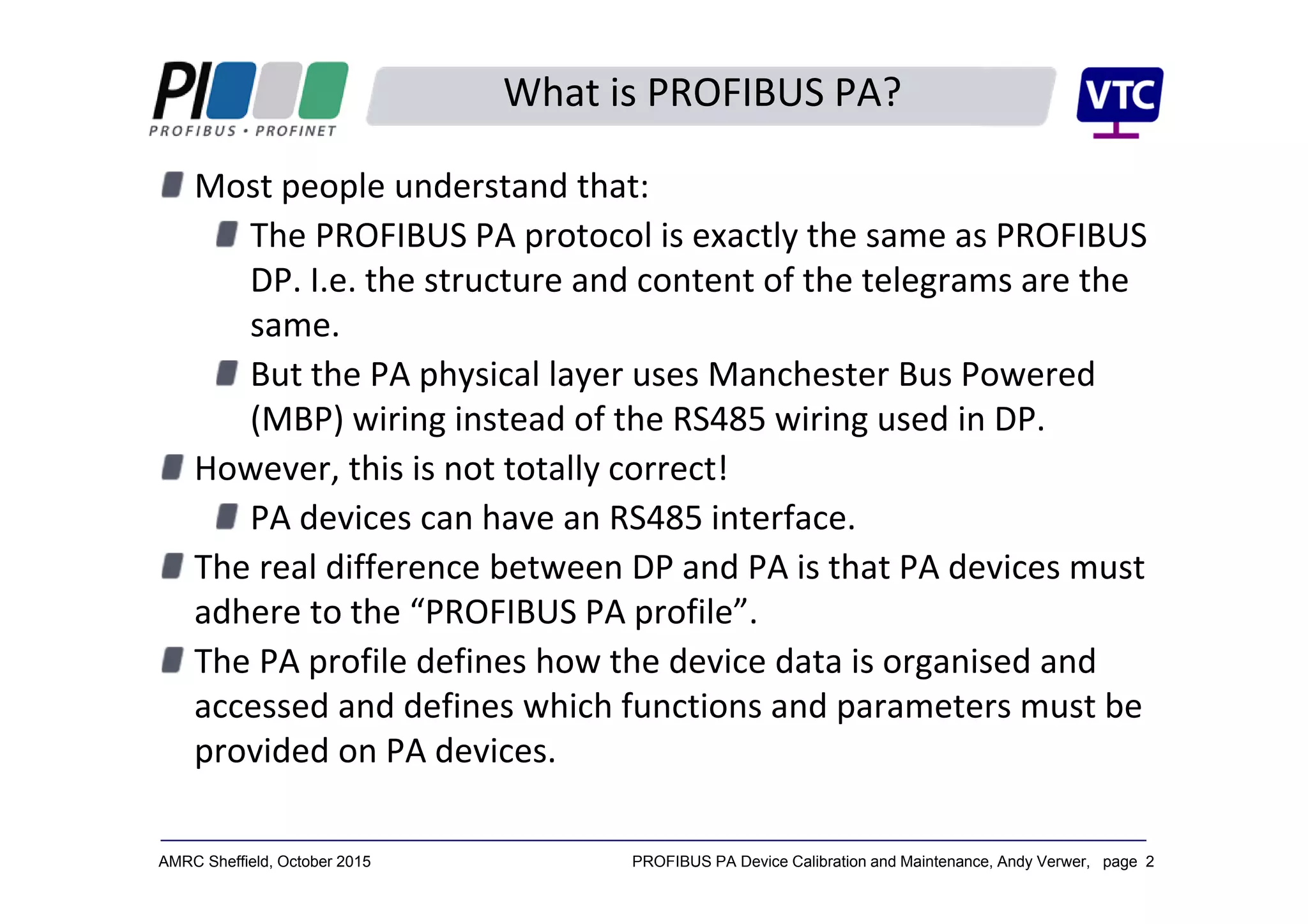
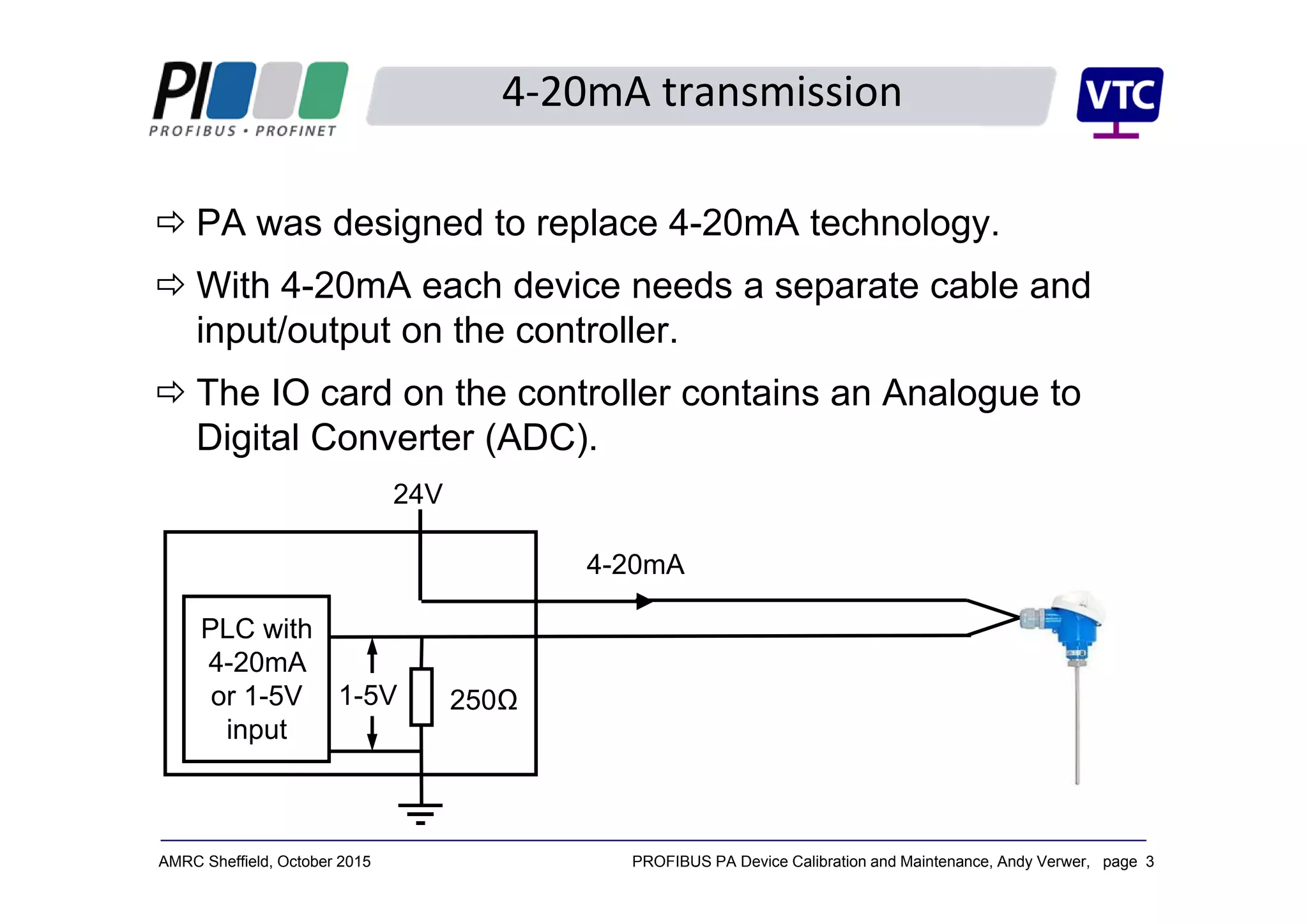
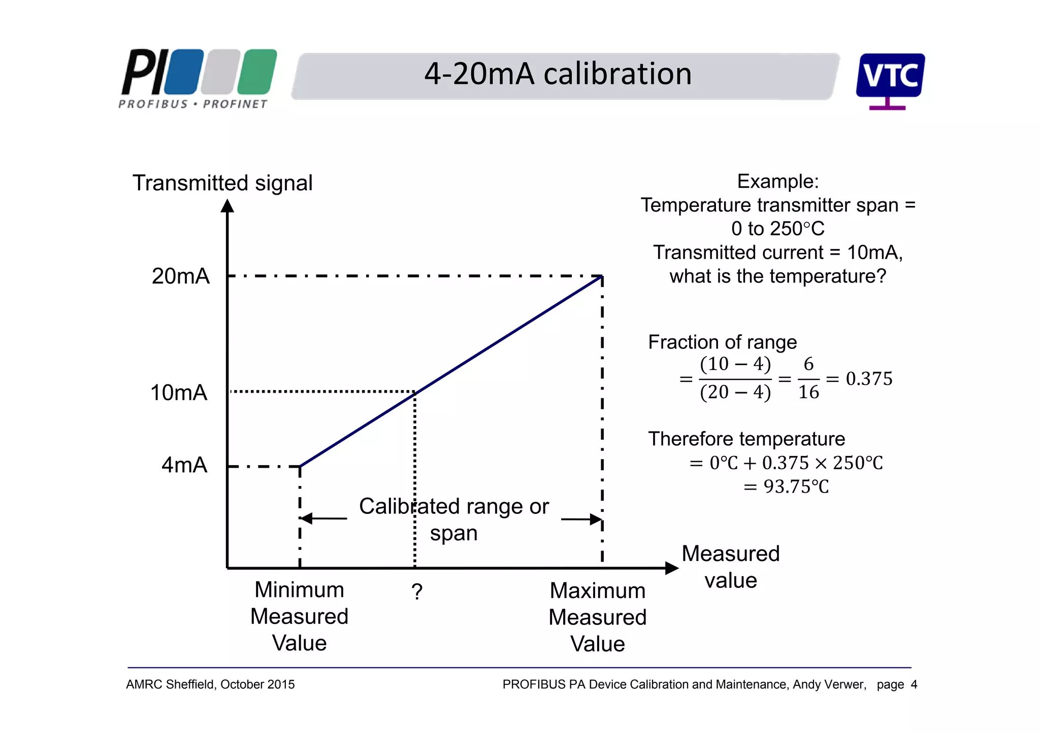
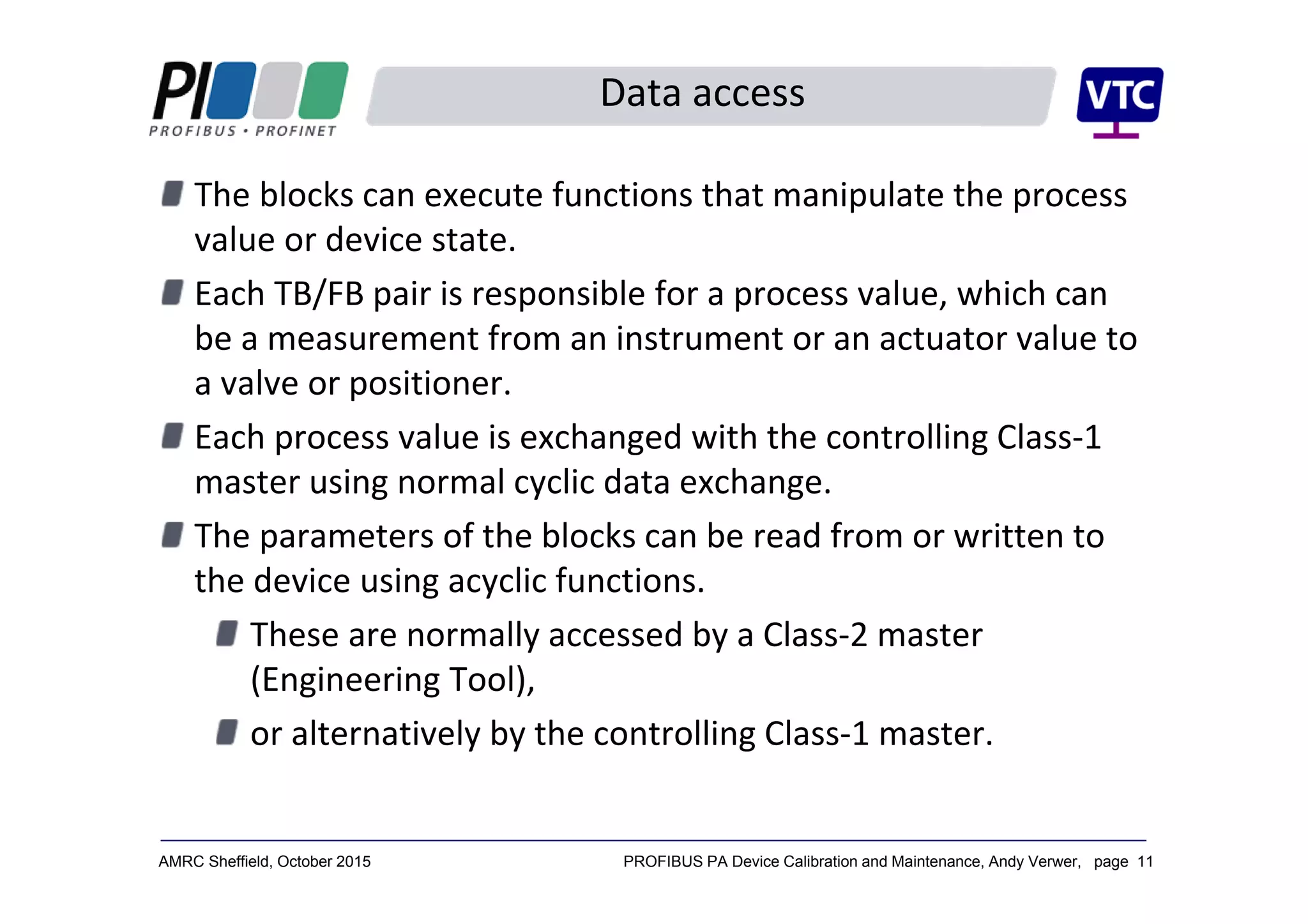
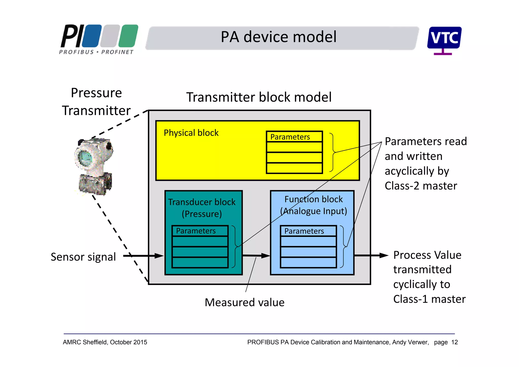
PROFIBUS PA 
Device 
Calibration and 
Maintenance
Andy Verwer,
Verwer Training
& Consultancy
Ltd
Accredited PI
Training Centre
PROFINET,
PROFIBUS and
IO-Link Seminar
AMRC Sheffield
14 October 2015
PROFIBUS PA Device Calibration and Maintenance, Andy Verwer, page 2AMRC Sheffield, October 2015
What is PROFIBUS PA?
Most people understand that:
The PROFIBUS PA protocol is exactly the same as PROFIBUS 
DP. I.e. the structure and content of the telegrams are the 
same.
But the PA physical layer uses Manchester Bus Powered 
(MBP) wiring instead of the RS485 wiring used in DP.
However, this is not totally correct!
PA devices can have an RS485 interface.
The real difference between DP and PA is that PA devices must 
adhere to the “PROFIBUS PA profile”. 
The PA profile defines how the device data is organised and 
accessed and defines which functions and parameters must be 
provided on PA devices.
PROFIBUS PA Device Calibration and Maintenance, Andy Verwer, page 3AMRC Sheffield, October 2015
4‐20mA transmission
 PA was designed to replace 4-20mA technology.
 With 4-20mA each device needs a separate cable and
input/output on the controller.
 The IO card on the controller contains an Analogue to
Digital Converter (ADC).
PLC with
4-20mA
or 1-5V
input
24V
250Ω1-5V
4-20mA
PROFIBUS PA Device Calibration and Maintenance, Andy Verwer, page 4AMRC Sheffield, October 2015
4‐20mA calibration
Transmitted signal
Measured
value
Calibrated range or
span
Minimum
Measured
Value
Maximum
Measured
Value
20mA
4mA
Example:
Temperature transmitter span =
0 to 250°C
Transmitted current = 10mA,
what is the temperature?
Fraction of range
10 4
20 4
6
16
0.375
Therefore temperature
0 0.375 250
93.75
10mA
?
PROFIBUS PA Device Calibration and Maintenance, Andy Verwer, page 5AMRC Sheffield, October 2015
PROFIBUS PA
4‐20mA devices always connect to a 4‐20mA input on a 
remote IO unit or controller IO card.
Communication is analogue.
Scaling is done in the controller (PLC).
The controller only sees the value as a 12 or 16 bit integer 
value (range 0 to 4095, or 0 to 65535).
PROFIBUS PA is quite different.
The Devices all communicate digitally.
The scaling is done in the device (i.e. the instrument).
Transmitted process values are sent as floating point 
numbers, scaled and calibrated in engineering units (e.g. 
°C, mBar, litres/minute, m3 etc.)
PROFIBUS PA Device Calibration and Maintenance, Andy Verwer, page 6AMRC Sheffield, October 2015
The PA Profile
The PROFIBUS PA Profile provides a mandatory specification 
for all PA devices.
Defines the device functions, data organisation and 
formatting.
The Process Value is always communicated in a standardised 
format:
Standard floating point format for analogue values.
Standard digital format for discrete values.
Plus a standardised status value which encodes the quality 
of the measurement (good, bad, usable etc.)
The profile also specifies mandatory device parameters so that 
standardised tools can be used to access this data with any 
manufacturer’s devices.
PROFIBUS PA Device Calibration and Maintenance, Andy Verwer, page 7AMRC Sheffield, October 2015
Data representation
The process values of PA devices are transmitted as:
32‐bit floating‐point values (analogue devices), or
discrete bits or bytes (switching devices).
Together with a “status byte” containing information about 
the “quality” of the process value.
Typical analogue instrument or actuator value: 
Byte 1 Byte 2 Byte 3 Byte 5Byte 4
Floating point number representing the 
process value in “engineering units”
Status byte 
representing the 
quality of the value
PROFIBUS PA Device Calibration and Maintenance, Andy Verwer, page 8AMRC Sheffield, October 2015
Status byte interpretation
The status byte consists of eight bits representing signal 
quality.
The most significant bit is used to indicate the overall quality 
of the associated value:
= Bad (‹80hex, 12810)
= Good (80hex, 12810)
The remaining bits in the status byte give further 
information on the device status. 
0 X X X X X X X
1 X X X X X X X
PROFIBUS PA Device Calibration and Maintenance, Andy Verwer, page 9AMRC Sheffield, October 2015
The PA profile structures a device into “Blocks”:
A Physical Block, PB
Contains the parameters and functions of the device 
hardware and installation etc.
One or more Transducer Blocks, TB
Describes the interface to the process, i.e. the sensor or 
actuator characteristics.
One or more Function Blocks, FB
Contains common signal manipulation and automation 
functions.
Each device also incorporates a Resource or Device 
Manager.
Describes which blocks are available in the device and a 
look‐up table for the device parameters.
PA device model
PROFIBUS PA Device Calibration and Maintenance, Andy Verwer, page 10AMRC Sheffield, October 2015
Block header
Block header
Block header
Block header
Device
Physical block, PB
Transducer block, TB Function block, FB
Resource Manager
Directory header
List of blocks
Pointers to blocks
PB pointer
TB pointer
TB pointer
FB pointer
FB pointer
Block header
Block header Block header
parameters
parameters parameters
Parameter order 
and semantics 
described in PA 
profile.
PA device model
PROFIBUS PA Device Calibration and Maintenance, Andy Verwer, page 11AMRC Sheffield, October 2015
The blocks can execute functions that manipulate the process 
value or device state.
Each TB/FB pair is responsible for a process value, which can 
be a measurement from an instrument or an actuator value to 
a valve or positioner.
Each process value is exchanged with the controlling Class‐1 
master using normal cyclic data exchange.
The parameters of the blocks can be read from or written to 
the device using acyclic functions.
These are normally accessed by a Class‐2 master 
(Engineering Tool),
or alternatively by the controlling Class‐1 master.
Data access
PROFIBUS PA Device Calibration and Maintenance, Andy Verwer, page 12AMRC Sheffield, October 2015
Physical block
Transducer block 
(Pressure)
Function block 
(Analogue Input)
Sensor signal
Measured value
transmitted 
cyclically to 
Class‐1 master
Transmitter block model
Parameters read 
and written 
acyclically by 
Class‐2 master
Process Value
Parameters Parameters
Parameters
PA device model
Pressure 
Transmitter
PROFIBUS PA Device Calibration and Maintenance, Andy Verwer, page 13AMRC Sheffield, October 2015
Transducer blocks reflect the measurement or actuation that is 
taking place.
Transducer blocks are available for a wide range of 
instruments and actuators:
Temperature – RTD, thermocouple etc.
Pressure/differential pressure etc.
Level – hydrostatic, displacement, microwave, capacitance 
etc.
Flow – head meters, electromagnetic, Coriolis etc.
Transducer blocks
PROFIBUS PA Device Calibration and Maintenance, Andy Verwer, page 14AMRC Sheffield, October 2015
Temperature transducer block
PROFIBUS PA Device Calibration and Maintenance, Andy Verwer, page 15AMRC Sheffield, October 2015
Level transducer block
PROFIBUS PA Device Calibration and Maintenance, Andy Verwer, page 16AMRC Sheffield, October 2015
Function blocks contain common signal conditioning and 
automation functions.
There are currently three function blocks for inputs and two 
for outputs defined in the PA profile:
Analogue input, Analogue output,
Discrete input, Discrete output,
Totaliser (for use with flow measurement),
The analogue input block is the most common block, being 
used for all analogue instruments. It provides for each 
measurement:
Linearisation, filtering, alarms, fail‐safe action, simulation 
facilities and auto/manual mode control.
Function blocks
PROFIBUS PA Device Calibration and Maintenance, Andy Verwer, page 17AMRC Sheffield, October 2015
Analogue input function block
PROFIBUS PA Device Calibration and Maintenance, Andy Verwer, page 18AMRC Sheffield, October 2015
PA engineering tools
The functions and addressing to access parameters is defined in 
the PA profile.
Specialist PA engineering tools are available that can interact 
with devices without requiring explicit addresses.
PA engineering tools come in two types:
EDD tools (such as Siemens PDM)
FDT tools (such as E+H FieldCare, P+F PactWare etc.)
(EDD = Electronic Device Description, FDT = Field Device Tool)
PROFIBUS PA Device Calibration and Maintenance, Andy Verwer, page 19AMRC Sheffield, October 2015
FDT/DTM tools
FDT is an open technology that is defined by international 
standards and supported by several manufacturers (E+H 
FieldCare, P+F PactWare etc.)
The FTD tools use Device Type Managers (DTMs) to establish 
the required communications and to access parameters in the 
different devices.
Two different types of DTM are available:
Communications DTMs (CommDTMs) – establish a 
communication route to the devices.
Device DTMs – to access data within a particular type of 
device.
PROFIBUS PA Device Calibration and Maintenance, Andy Verwer, page 20AMRC Sheffield, October 2015
FDT/DTM tools
ProfiTrace supports a CommDTM that allows ProfiTrace to be 
used in any FDT environment.
An additional licence is required.
ProfiTrace must not be running, but is automatically initialised 
when the CommDTM is used within an FDT environment.
PROFIBUS PA Device Calibration and Maintenance, Andy Verwer, page 21AMRC Sheffield, October 2015
FDT/DTM
• The FDT provides a standardised framework in 
which the required DTMs can be loaded and run.
• The device DTMs operate underneath the 
CommDTM in order to provide a route to the 
devices.
CommDTM
Device DTMs
ProfiCore
DP
PA
Transparent 
coupler
Devices
PROFIBUS PA Device Calibration and Maintenance, Andy Verwer, page 22AMRC Sheffield, October 2015
Specialist Calibration tools
Specialist calibration tools are available from several 
manufacturers.
Beamex, for example, offer specialist calibration tools with 
capabilities for pressure, temperature and various electrical 
signals.
The Beamex MC6 incorporates a communicator for PROFIBUS 
PA instruments (Based on EDD technology)

Profibus PA device calibration and maintenance - Andy Verwer

  • 1.
    PROFIBUS PA  Device  Calibration and  Maintenance Andy Verwer, Verwer Training &Consultancy Ltd Accredited PI Training Centre PROFINET, PROFIBUS and IO-Link Seminar AMRC Sheffield 14 October 2015
  • 2.
    PROFIBUS PA DeviceCalibration and Maintenance, Andy Verwer, page 2AMRC Sheffield, October 2015 What is PROFIBUS PA? Most people understand that: The PROFIBUS PA protocol is exactly the same as PROFIBUS  DP. I.e. the structure and content of the telegrams are the  same. But the PA physical layer uses Manchester Bus Powered  (MBP) wiring instead of the RS485 wiring used in DP. However, this is not totally correct! PA devices can have an RS485 interface. The real difference between DP and PA is that PA devices must  adhere to the “PROFIBUS PA profile”.  The PA profile defines how the device data is organised and  accessed and defines which functions and parameters must be  provided on PA devices.
  • 3.
    PROFIBUS PA DeviceCalibration and Maintenance, Andy Verwer, page 3AMRC Sheffield, October 2015 4‐20mA transmission  PA was designed to replace 4-20mA technology.  With 4-20mA each device needs a separate cable and input/output on the controller.  The IO card on the controller contains an Analogue to Digital Converter (ADC). PLC with 4-20mA or 1-5V input 24V 250Ω1-5V 4-20mA
  • 4.
    PROFIBUS PA DeviceCalibration and Maintenance, Andy Verwer, page 4AMRC Sheffield, October 2015 4‐20mA calibration Transmitted signal Measured value Calibrated range or span Minimum Measured Value Maximum Measured Value 20mA 4mA Example: Temperature transmitter span = 0 to 250°C Transmitted current = 10mA, what is the temperature? Fraction of range 10 4 20 4 6 16 0.375 Therefore temperature 0 0.375 250 93.75 10mA ?
  • 5.
    PROFIBUS PA DeviceCalibration and Maintenance, Andy Verwer, page 5AMRC Sheffield, October 2015 PROFIBUS PA 4‐20mA devices always connect to a 4‐20mA input on a  remote IO unit or controller IO card. Communication is analogue. Scaling is done in the controller (PLC). The controller only sees the value as a 12 or 16 bit integer  value (range 0 to 4095, or 0 to 65535). PROFIBUS PA is quite different. The Devices all communicate digitally. The scaling is done in the device (i.e. the instrument). Transmitted process values are sent as floating point  numbers, scaled and calibrated in engineering units (e.g.  °C, mBar, litres/minute, m3 etc.)
  • 6.
    PROFIBUS PA DeviceCalibration and Maintenance, Andy Verwer, page 6AMRC Sheffield, October 2015 The PA Profile The PROFIBUS PA Profile provides a mandatory specification  for all PA devices. Defines the device functions, data organisation and  formatting. The Process Value is always communicated in a standardised  format: Standard floating point format for analogue values. Standard digital format for discrete values. Plus a standardised status value which encodes the quality  of the measurement (good, bad, usable etc.) The profile also specifies mandatory device parameters so that  standardised tools can be used to access this data with any  manufacturer’s devices.
  • 7.
    PROFIBUS PA DeviceCalibration and Maintenance, Andy Verwer, page 7AMRC Sheffield, October 2015 Data representation The process values of PA devices are transmitted as: 32‐bit floating‐point values (analogue devices), or discrete bits or bytes (switching devices). Together with a “status byte” containing information about  the “quality” of the process value. Typical analogue instrument or actuator value:  Byte 1 Byte 2 Byte 3 Byte 5Byte 4 Floating point number representing the  process value in “engineering units” Status byte  representing the  quality of the value
  • 8.
    PROFIBUS PA DeviceCalibration and Maintenance, Andy Verwer, page 8AMRC Sheffield, October 2015 Status byte interpretation The status byte consists of eight bits representing signal  quality. The most significant bit is used to indicate the overall quality  of the associated value: = Bad (‹80hex, 12810) = Good (80hex, 12810) The remaining bits in the status byte give further  information on the device status.  0 X X X X X X X 1 X X X X X X X
  • 9.
    PROFIBUS PA DeviceCalibration and Maintenance, Andy Verwer, page 9AMRC Sheffield, October 2015 The PA profile structures a device into “Blocks”: A Physical Block, PB Contains the parameters and functions of the device  hardware and installation etc. One or more Transducer Blocks, TB Describes the interface to the process, i.e. the sensor or  actuator characteristics. One or more Function Blocks, FB Contains common signal manipulation and automation  functions. Each device also incorporates a Resource or Device  Manager. Describes which blocks are available in the device and a  look‐up table for the device parameters. PA device model
  • 10.
    PROFIBUS PA DeviceCalibration and Maintenance, Andy Verwer, page 10AMRC Sheffield, October 2015 Block header Block header Block header Block header Device Physical block, PB Transducer block, TB Function block, FB Resource Manager Directory header List of blocks Pointers to blocks PB pointer TB pointer TB pointer FB pointer FB pointer Block header Block header Block header parameters parameters parameters Parameter order  and semantics  described in PA  profile. PA device model
  • 11.
    PROFIBUS PA DeviceCalibration and Maintenance, Andy Verwer, page 11AMRC Sheffield, October 2015 The blocks can execute functions that manipulate the process  value or device state. Each TB/FB pair is responsible for a process value, which can  be a measurement from an instrument or an actuator value to  a valve or positioner. Each process value is exchanged with the controlling Class‐1  master using normal cyclic data exchange. The parameters of the blocks can be read from or written to  the device using acyclic functions. These are normally accessed by a Class‐2 master  (Engineering Tool), or alternatively by the controlling Class‐1 master. Data access
  • 12.
    PROFIBUS PA DeviceCalibration and Maintenance, Andy Verwer, page 12AMRC Sheffield, October 2015 Physical block Transducer block  (Pressure) Function block  (Analogue Input) Sensor signal Measured value transmitted  cyclically to  Class‐1 master Transmitter block model Parameters read  and written  acyclically by  Class‐2 master Process Value Parameters Parameters Parameters PA device model Pressure  Transmitter
  • 13.
    PROFIBUS PA DeviceCalibration and Maintenance, Andy Verwer, page 13AMRC Sheffield, October 2015 Transducer blocks reflect the measurement or actuation that is  taking place. Transducer blocks are available for a wide range of  instruments and actuators: Temperature – RTD, thermocouple etc. Pressure/differential pressure etc. Level – hydrostatic, displacement, microwave, capacitance  etc. Flow – head meters, electromagnetic, Coriolis etc. Transducer blocks
  • 14.
    PROFIBUS PA DeviceCalibration and Maintenance, Andy Verwer, page 14AMRC Sheffield, October 2015 Temperature transducer block
  • 15.
    PROFIBUS PA DeviceCalibration and Maintenance, Andy Verwer, page 15AMRC Sheffield, October 2015 Level transducer block
  • 16.
    PROFIBUS PA DeviceCalibration and Maintenance, Andy Verwer, page 16AMRC Sheffield, October 2015 Function blocks contain common signal conditioning and  automation functions. There are currently three function blocks for inputs and two  for outputs defined in the PA profile: Analogue input, Analogue output, Discrete input, Discrete output, Totaliser (for use with flow measurement), The analogue input block is the most common block, being  used for all analogue instruments. It provides for each  measurement: Linearisation, filtering, alarms, fail‐safe action, simulation  facilities and auto/manual mode control. Function blocks
  • 17.
    PROFIBUS PA DeviceCalibration and Maintenance, Andy Verwer, page 17AMRC Sheffield, October 2015 Analogue input function block
  • 18.
    PROFIBUS PA DeviceCalibration and Maintenance, Andy Verwer, page 18AMRC Sheffield, October 2015 PA engineering tools The functions and addressing to access parameters is defined in  the PA profile. Specialist PA engineering tools are available that can interact  with devices without requiring explicit addresses. PA engineering tools come in two types: EDD tools (such as Siemens PDM) FDT tools (such as E+H FieldCare, P+F PactWare etc.) (EDD = Electronic Device Description, FDT = Field Device Tool)
  • 19.
    PROFIBUS PA DeviceCalibration and Maintenance, Andy Verwer, page 19AMRC Sheffield, October 2015 FDT/DTM tools FDT is an open technology that is defined by international  standards and supported by several manufacturers (E+H  FieldCare, P+F PactWare etc.) The FTD tools use Device Type Managers (DTMs) to establish  the required communications and to access parameters in the  different devices. Two different types of DTM are available: Communications DTMs (CommDTMs) – establish a  communication route to the devices. Device DTMs – to access data within a particular type of  device.
  • 20.
    PROFIBUS PA DeviceCalibration and Maintenance, Andy Verwer, page 20AMRC Sheffield, October 2015 FDT/DTM tools ProfiTrace supports a CommDTM that allows ProfiTrace to be  used in any FDT environment. An additional licence is required. ProfiTrace must not be running, but is automatically initialised  when the CommDTM is used within an FDT environment.
  • 21.
    PROFIBUS PA DeviceCalibration and Maintenance, Andy Verwer, page 21AMRC Sheffield, October 2015 FDT/DTM • The FDT provides a standardised framework in  which the required DTMs can be loaded and run. • The device DTMs operate underneath the  CommDTM in order to provide a route to the  devices. CommDTM Device DTMs ProfiCore DP PA Transparent  coupler Devices
  • 22.
    PROFIBUS PA DeviceCalibration and Maintenance, Andy Verwer, page 22AMRC Sheffield, October 2015 Specialist Calibration tools Specialist calibration tools are available from several  manufacturers. Beamex, for example, offer specialist calibration tools with  capabilities for pressure, temperature and various electrical  signals. The Beamex MC6 incorporates a communicator for PROFIBUS  PA instruments (Based on EDD technology)