1. The document proposes using UDP Lite as an alternative to UDP to support real-time streaming applications over noisy wireless channels by providing a more error resilient transport layer.
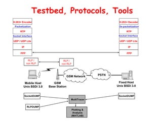
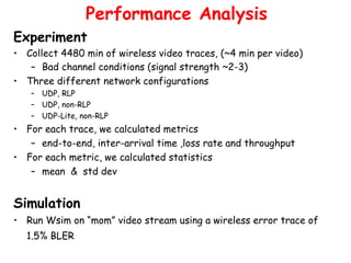
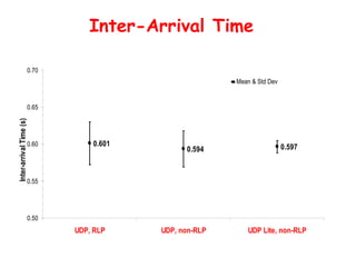
2. It describes experiments comparing the performance of UDP, UDP with a radio link protocol (RLP), and UDP Lite without RLP for wireless video streaming using collected wireless error traces.
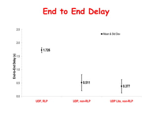
3. The results show that UDP Lite without RLP provides less end-to-end delay, lower packet loss, and higher throughput than UDP or UDP with RLP for wireless video streaming applications.


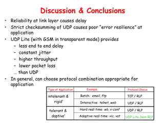


![Guía iniciación a_la_codificación_(enero_08)[1]](https://cdn.slidesharecdn.com/ss_thumbnails/guainiciacinalacodificacinenero081-120126044637-phpapp02-thumbnail.jpg?width=640&height=640&fit=bounds)


