Download to read offline

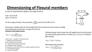
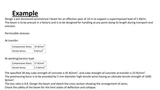


This document discusses the dimensioning and design of precast concrete bridge elements. It provides guidelines for the ratio of height to depth (hf/d) and width of the bottom flange to total width (bw/b) of unsymmetrical I-girders. It also discusses estimating the self-weight of beams using equations that consider the density of concrete, acceleration due to gravity, and load factors. An example is given to design a precast pre-tensioned symmetrical I-beam for a 10m span with a superimposed load of 5kN/m.


